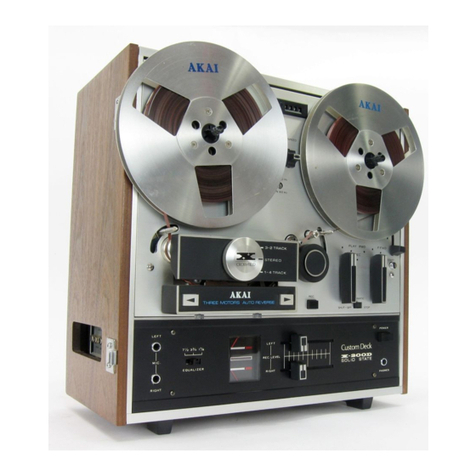
Akai DR4vr User manual

DR4vr
HARD DISK RECORDER
WARNING
To prevent tire or shock hazard, do not
expose ttiis app iance to rain or moisture.
Operator's Manual

WARNINGII
To prevent fire or shock hazard, do hot expose this appliiahee to
rain or moisture.
6B-En
CAUTION
RISK OF a.ECTRIC SHOCK
DO NOT OPEN
CAUTION :TO REDUCF THE RISK OF ELECTRIC SHOCK,
DO NOT h. :MOVE COVER (OR BACK).
NO USER-SERVICEABLE PARTS INSIDE.
REFER SERVICING TO QUALIFIED SERVICE PERSONNEL.
THE SYMBOLS ARE RULED BY UL STANDARDS (U.S.A)
The lightning flash with the arrowhead symbol superimposed
across agraphical representation of aperson, within an equilateral
triangle, is intended to alert the user to ttie presence of uninsulated
"dangerous voltage" within the product's enclosure; that may be of
sufficient magnitude to constitute arisk of electric shock.
rThe exclamation point with^
alert the user to the presence of important operating and mainte-
nance (servicing) instructions in the literature accompanying the
appliance.
5A-En

AKAI DR4vr
Hard Disk f^ecorder
Owner's Manual
(Software Version 4.0)
To show our support for the protection of the earth's environment,
this manual has been printed entirely on recycled paper.

WARNING
Power requirements for electrical equipment vary from area to area. Please ensure that
your DR4vr meets the power requirements in your area. If in doubt, consult aqualified
electrician or Akai Professional dealer.
120VAC @60Hz for USA and Canada
220-230VAC @50Hz for Europe (excluding UK)
240VAC @50Hz for UK and Australia
PROTECTING YOURSELF AND THE DR4vr
*Nevertouch the AC plug with wet hands.
*Always disconnect the DR4vrfrom the powersupply by pulling on the plug, not the
xord.
*Allow only an Akai Professional dealer or qualified professional engineer to repair
or reassemble the DR4vr. Apart from voiding the warranty, unauthorized engineers
might touch live internal parts and receive aserious electric shock.
*Do not put, or allow anyone to put any object, especially metal objects, into the
DR4vr.
*Use only ahousehold AC power supply. Never use aDC power supply.
*If water or any other liquid is spilled into or onto the DR4vr, disconnect the power,
and call your dealer.
*N/lake sure that the unit is well-ventilated, and away from direct sunlight.
*To avoid damage to interna! circuitry, as well as the external finish, keep the DR4vr
away from sources of direct heat (stoves, radiators, etc.).
*Avoid using aerosol insecticides, etc. near the DR4vr. They may damage the
surface, and may ignite.
*Do not use denaturated alcohol, thinner or similar chemicals to clean the DR4vr.
They will damage the finish.
*Modification of this equipment is dangeixjus, and can result in the functions of the
DR4vr being impaired. Never attempt to modify the equipment in any way.
*.In order to assure optimum performance of your DR4vr, select the setup location
carefully, and make sure the equipment is used properly. Avoid setting up the
DR4vr in the following locations:
1.In ahumid or dusty environment
2. In aroom with poor ventilation
3. On asurface which is not horizontal
4. Inside avehicle such as acar, where it will be subject to vibration
5. In an extremely hot or cold environment

Precautions When Using the Optional Internal HD540 Hard Disk Drive
1.The hard disk drive has extremely high precision and is vulnerable to shock and
vibration. If transporting the DR4vr by either land or air, we recommend packing it in a
shell-shaped case lined with urethane rubber which meets ATA specifications.
2. Make sure the DR4vr Is used in the horizontal position. Do not set it on end or tilt it when
using it.
3. If the DR4vr is moved from acold location to awarm one, or if the temperature has been
raised suddenly, condensation may form inside the DR4vr. If it is impossible to avoid
conditions like these, let the DR4vr sit for at least an hour in the new location before
using it.
4. When setting up the 0R4vr, make sure the ventilation opening is not blocked. Also, if
using the DR4vr in arack that contains other equipment, make sure sufficient ventilation
space is assured on all sides (approx. 44 mm of space between the DR4vr and any
equipment mounted above or below it in the rack).

WARNING
THIS APPARATUS MUST BE EARTHED
IMPORTANT
This equipment is fitted witli an approved non-rewireable UK mains plug.
To change the fuse in this type of plug proceed as follows:
1) Remove the fuse cover and old fuse.
2) Fit anew fuse which should be aBS1 362 5Amp A.S.T.A or BSI approved type.
3) Refit the fuse cover.
If the AC mains plug fitted to the lead supplied with this equipment is not suitable for your
type of AC outlet sockets, it should be changed to an AC mains lead, complete with moulded
plug, to the appropriate type. If this is not possible, the plug should be cut off and acorrect
one fitted to suit the AC outlet. This should be fused at 5Amps.
If aplug without afuse is used, the fuse at the distribution board should NOT BE GREATER
than 5Amp.
PLEASE NOTE: THE SEVERED PLUG MUST BE DESTROYED TO AVOID APOS-
SIBLE SHOCK HAZARD SHOULD IT BE INSERTED INTO A13AMP
SOCKET ELSEWHERE.
The wires in this mains lead are coloured in accordance with the following code:
GREEN and YELLOW —EARTH
BLUE —NEUTRAL
BROWN —LIVE
As the colours of the wires in the mains lead of this apparatus may not correspond with the
coloured markings identifying the terminals in your plug, please proceed as follows:
The wire which is coloured GREEN and YELLOW must be connected to the terminal
which is marked with the letter Eor with the safety earth symbol ±: or coloured GREEN
or coloured GREEN and YELLOW.
The wire which is coloured BLUE must be connected to the terminal which is marked
with the letter Nor coloured BLACK.
The wire which is coloured BROWN must be connected to the terminal which is marked
with the letter Lor coloured RED.
THIS APPARATUS MUST BE EARTHED
Ensure that all the terminals are securely tightened and no loose strands of wire exist.
Before replacing the plug cover, make certain the cord grip is clamped over the outer sheath
of the lead and not simply over the wires.
6D-En

FCC WARNING
This equipment has been tested and found to comply with the limits for aClass Bdigital
device pursuant to Part 15 of tlie FCC rules. These limits are designed to provide
reasonable protection against harmful interference in aresidential installation. This
equipment generates, uses, and can radiate radio frequency energy and, if not installed
and used in accordance with the instructions, may cause harmful interference to radio
communications. However, there is no guarantee that interference will not occur in a
particular installation. If this equipment does cause harmful interference to radio or
television reception, which can be determined by turning the equipment off and on, the
user is encouraged to try to correct the interference by one or more of the following
measures:
-Reorient or relocate the receiving antenna.
-Increase the separation between the equipment and receiver.
-Connect the equipment into an outlet on acircuit different from that to which the
receiver is connected.
-Consult the dealer or an experienced radio/TV technician for help. 21B-En
AVIS POUR LES ACHETEURS CANADIENS DU DR4vr
Le present appareil numerique n'ement pas des bruits radio6lectriques d^passant les
llmltes applicables aux appareils num^riques de la Class Bprescrites dans le Rdglement
sur le brouillage radio6lectrique 6dict6 par le miniature des Communications du Canada
27-F
This digital apparatus does not exceed the Class Blimits for radio noise emissions from
digital apparatus set out in the Radio Interference Regulations of the Canadian
Department of Communications. 27-En
fOr kunden in der bundesrepublik deutschland
Bescheinigung von AKAI
Hiermit wird bescheinigt, daB das GerSt AKAI
DR4vr
in Obereinstimmung mit den Bestimmungen der
Amtsblattverfiigung 1046/1984
funkentstSrt ist.
Der Deutschen Bundespostwurde das Inverkehrbringen dieses Gerates angezeigt und
die Berichtigung zur Uberprufung der Serie auf Einhattung derBestimmungen eingerSumt.
AKAI ELECTRIC CO., LTD 17B-G
COPYRIGHT NOTICE
The AKAI DR4vr is acomputer-based device, and as such contains and uses software in
ROMs. This software, and all related documentation, including this Owner's Manual,
contain proprietary information which is protected by copyright laws. All rights are reserved.
No part of the software or its documentation may be copied, transferred or modified. You
may not modify, adapt, translate, lease, distribute, resell for profit or create derivative works
based on the software and its related documentation or any part there of without prior written
consent from AKAI Electric Co. Ltd, Tokyo, Japan.

WARRANTY
AKAI Electric Co. Ltd warrants its products, when purchased from an authorized AKAl dealer, to be
free from defects in materials and workmanship for aperiod of 12 (twelve) months from the date of
purchase. Warranty service is effective and available to the original purchaser only, and only on
completion and return of the AKAI Warranty Registration Card within 14 days of purchase.
Warranty coverage Is valid for factory-authorized updates to AKAI instruments and their software,
when their installation is performed by an authorized AKAI Service Centre, and aproperly completed
Warranty Registration has been returned to your Akai Professional dealer.
To obtain service under this warranty, the product must, on discovery of the defect, be properly
packed and shipped to the nearest AKAI Service Centre. The party requesting warranty service must
provide proof of original ownership and date of purchase of the product.
If the warranty is valid, AKAI will, without charge for parts or labour, either repair or replace the
defective part(s). Without avalid warranty, the entire cost of the repair (parts and labour) Is the
responsibility of the product's owner.
AKAI warrants that it will make all necessary adjustments, repairs and replacements at no cost to the
original owner within 12 (twelve) months of the purchase date if:
1The product fails to perform its specified functions due to failure of one or more of its
components.
2The product fails to perform its specified functions due to defects in workmanship.
3The product has been maintained and operated by the owner in strict accordance with the
written instructions for proper maintenance and use as specified in this Operator's Manual.
Before purchase and use, owners should determine the suitability of the product for their intended
use, and the owner assumes all risk and liability whatsoever in connection therewith. AKAI shall not
be liable for any injury, loss or damage, direct or consequential, arising out of the use, or inability to
use the product.
The warranty provides only those benefits specified, and does not cover defects or repairs needed
as aresult of acts beyond the control of AKAI, including, but not limited to:
1Damage caused by abuse, accident or negligence. AKAI will not cover under warranty any
original factory disk damaged or destroyed asaresult of the owner's mishandling.
2Damage caused by any tampering, alteration or modification of the product: operating
software, mechanical or electronic components.
3Damage caused by failure to maintain and operate the product in strict accordance with the
written instructions for proper maintenance and use as specified in this Operator's Manual.
4Damage caused by repairs or attempted repairs by unauthorized persons.
5Damage caused by fire, smoke, falling objects, water or other liquids, or natural events such
as rain, floods, earthquakes, lightning, tomadoes, storms, etc.
€Damage caused by operation on improper voltages.
IMPORTANT NOTE: This warranty becomes void if the product or its software is electronically
modified, altered or tampered with in any way.
AKAI shall not be liable for costs involved in packing or preparing the product for shipping, with regard
to time, labour or materials, shipping or freight costs, or time and expenses involved in transporting
the product to and from an AKAI Authorized Service Centre or Authorized Dealer.
'AKAI will not cover under warranty an apparent malfunction that is determined to be user error, or the
owner's inability to use the product.
THE DURATION OF ANY OTHER WARRANTIES. WHETHER IMPLIED OR EXPRESS, INCLUD-
ING BUT NOT LIMITED TO THE IMPLIED CONDITION OF MERCHANTABILITY, IS LIMITED TO
THE DURATION OF THE EXPRESS WARRANTY HEREIN.
AKAI hereby excludes incidental or consequential damages, including but not limited to:
1Loss of time
2Inconvenience
3Delay in performance of the Warranty
4The loss of use of the product
5Commercial loss
6Breach of any express or implied warranty, including theImplied Warrantyof Merchantability,
applicable to this product

1
Table of Contents
Introduction 5
What is the DR4vr? 5
Features 5
Inside the DR4vr 7
1Front &Rear Panels 9
Front Panel 9
Rear Panel 15
2Getting Around the DR4vr 19
Sub Menus 19
Setting Parameters 19
Entering Time Values 19
Specifying the In Point &Out Point 20
Escape 20
3Setting Up \he DR4vr 21
Siting the DR4vr 21
Connecting the Power 21
Power On/Off 21
Typical DR4vr Setup 22
4Recording ;23
Analog Recording Setup 23
Digital Recording Setup 25
Virtual Tracks 27
How to Assign aVirtual Track to aChannel 27
Arming Channels 27
Setting Levels 29
Starting &Stopping Recording 29
Manual Punch In/Out 30
Footswitch Punch In/Out 31
Auto Punch In/Out 32
Auto Monitor 33
Rehearsal 33
Recording Undo 34
Recording and Limited Disk Space 35
Available Recording Time Display 35
$Playbdcic 37
Starting &Stopping 37
Play to Out 37
Repeat 38
Varipitch 39
6Ping-pong rtiode 41
Setting Monaural Ping-pong mode 41
Setting Stereo Ping-pong mode 41
7Locate Functions 51
Locating to aSpecific Point 5
1
Direct Locate Points (1-8 Keys) 52
Stack Locate Points 53
Version 4.0 12/95

2
Last Memory 54
Preroll 54
@Tim@ Oisploy 55
Setting Relative Time to Zero 55
Setting aRelative Time Offset 56
Time Display Relative to Any Point 57
9Editing 59
Undoing an Edit 60
Copy 60
Copy+Insert 62
Move 63
Move+lnsert 65
Erase 66
Delete 67
Insert 68
10 Hard Disks 69
Choosing aHard Disk 69
MO Disks 69
Hard Disk Size 70
SCSI 70
SCSl-A &SCSI-B 70
SCSI Cables 71
SCSlIDs 71
SCSI Termination 72
Checking for Disks on the SCSl-A Bus 72
External Hard Disk Operating Precautions 73
Formatting New Disks 74
Erasing Disks 75
Data Alignment 76
ABORT MESSAGE ON-OFF mode 78
nBackup i. 79
Backup to DAT 79
Backup via SCSl-B Bus 82
12 MIDI Synchronization 85
IB-l 13M MIDI Interface Card 85
Connection &Setup 85
Operation 85
MIDI Timecode Synchronization 86
MIDI Clock Synchronization 86
About MMC (MIDI Machine Control) 86
Tempo Map &Beat Map 87
Changing the Initial Tempo &Beat settings 88
Creating aTempo Map 89
Creating aBeat Map 90
13 SMPTE Synctironization 91
Connection &Setup 91
LTC Read Synchronization 91
Synchronization with an Offset 93
Punch In/Out &Slave Sync Playback 93
Vcrsitm 4.0 12/95

3
14 Synchronizing to Omer DR4vrs/DR4ds 95
AL-X50 Remote Cable 95
Connection 95
Setup .....96
Operation 96
REMOTE Sync with Other DR4vrs 96
Remote Sync Notes 97
15 Other Functions 99
Emphasis 99
SCMS 100
Appendix loi
Initial Settings 101
Troubleshooting 102
Display Messages 102
Error Messages 104
Specifications 105
MIDI Implementation Chart 106
Version 4.0 12/95

4
Version 4.0 12/95

Introduction 5
Introduction
From all at Akai, thank you for purchasing an Akai DR4vr Hard Disk Recorder, and welcome
to the exciting world of hard disk recording. Reading through this manual will provide you
with agood understanding of what the DR4vr is all about.
What is the DR4vr?
If you think of aconventional four-track recorder, replace all the analog circuitry with the latest
digital audio processing technology, replace the tape transport with ahard disk for near-instant
digital audio data access, you won't be far off the DR4vr concept.
However, the DR4vr also features aremarkable technological breakthrough called "virtual
tracks" that greatly expands the capabilities of the recorder far beyond those of aconventional
four-track. This innovation enables you to record and playback digital-quality sound on any
four channels you select from apossible 250 virtual tracks, greatly expanding your recording,
ping-pong recording, and mixdown capabilities. (See "Virtual Tracks" on page 27.)
The DR4vr uses hard disks as its recording media. You can extend the available recording time
according to your budget by adding external hard disks or using alarger internal hard disk. In
addition, the DR4vr provides nonlinear audio playback, and you can specify edit points and
search and locate with frame accuracy.
The DR4vr is not supplied as standard with an internal hard disk drive. Use Akai's optional
HD540 540MB internal hard disk, or consult your Akai professional dealer for details about
other DR4vr compatible hard disk drives.
Features
•4-channel, 250-virtual track hard disk recorder.
•16-bit linear PCM recording.
•17 channel minutes per 100MB of hard disk (fs @48 kHz).
•Up to four units can be connected for a16channel system.
•Up to seven SCSI hard disks can be connected.
•18-bit 64-times oversampling A/D converters.
•18-bit 8-tiraes oversampling D/A converters.
•Near-instant data access, no time consuming rewinds, etc.
•Instant playback start.
•Repeat playback with no gaps.
•Powerful stereo Ping-pong mode.
•8direct locate points. 100 stack locate points.
•Absolute and relative time modes, with sync offset.
•Beat/tempo map for MIDI Qock master operation.
•Adjustable preroll.
•Varipitch.
•Punch in/out includes: manual, auto (with rehearsal), and footswitch.
•Jog/shuttle wheel for locating edits.
•Edit functions include: copy, copy+insert, move, move+insert, erase, delete, insert, and edit
undo.
•Balanced 1/4 inch phone jack analog inputs and outputs (+4 dBu or -10 dBV).
•XLR and RCA/phono digital inputs and outputs (AES/EBU or S/PDIF).
Version 4.0 12/95

6Introduction
^^^^li^^MHHi^^
•Backup to DAT via digital I/O
•Remote connection for multiple DR4vrs/DR4ds synchronization.
•Remote control, from the Akai DL4.
•Optional HD540 540MB and larger hard disks can be installed.
•Optional IB-1 lOD Digital Interface allows four channel playback &recording via digital I/O.
•Optional IB-1 11 SInterface for connecting MO drives, personal computers, etc.
•Optional IB- 112T SMPTE/EBU Timecode Interface for SMPTE/EBU timecode
synchronization.
•Optional IB-1 13M MIDI Interface for MIDI sequencer synchronization.
Version 4.0 t2/9.S

Inside the DR4vt 7
Inside the DR4vr
Analog input
Analog output
^
Options
1•
I
1B-113MMIDIInterface t
I
I
IB-112TSMPTE Interface
JB-111SSCSI-B Interface •
JL
w1
Digital audio
data processor
Optional
HD540
Hard disk
H
0<3 Ooo
ZERO
RCTURN aPLAY
TO OUT
T
:si-
i
Digital l/O-A
Digital l/O-B i
!
I
IB-I^IODj
Option
SCSI-A Rennote
Hard disk
I
Hard disk
Hard disk
DR4vr 1
Df=)4vr
1
DR4vr
j
Recording media
L. »-
Synchronization to other DR4vrs
Version 4.0 12/95

8Introduction
Version 4.0 12/95

Front &Rear Panels 9
1Front &Rear Panels
Front Panel
00
00
Version 4.0 12/95

10 Chapter 1:Front &Rear Panels
1) POWER switch
This is the power switch. The rocker part of this switch is recessed in the ON position to
prevent accidental power off.
2) PHONES LEVEL
This control adjusts the headphone volume level.
3) PHONES connection
Astereo pair of headphones can be connected to this 1/4 inch stereo phone jack. Channels 1
and 3are on the left, channels 2and 4are on the right.
4) FOOT SW connection
Anormally closed type footswitch can be connected here for punch in/out operation. See
"Footswitch Punch In/Out" on page 31.
5) AUTO MONITOR/SOURCE key
This switch turns the auto monitor on and off. In the on position, monitoting is automatica;lly
switched between playback and source when recording. The off position allows you to monitor
the source during playback too. This is useful for practising with existing tracks before
recording. See"Auto Monitor" on page 33 and "Muting the source sound (AUTO
MONITOR)" on page 46.
6) REHEARSAL key
This key turns the rehearsal function on aird off. Rehearsal allows you to rehearse punch ins
and outs. During arehearsal, the monitor will switch to source at the punch in point, but
nothing will be recorded. See "Rehearsal" on page 33.
7) Ctiannel REC/VIRTUAL TRACK keys 1-4
These keys are used to arm channels for recording. Aflashing key indicates that achannel is
armed for recording, and alit key indicates recording in progress. In the sub-menu, you can
select virtual tracks in combination with the jog wheel. See "Arming Channels" and "How to
Assign aVirtual Track to aChannel" on page 27.
8) INPUT SELECT/CHANNEL SELECT keys 1/2, 3/4
These keys are used to select the input source, analog or digital, for each pair of channels. LED
indicators show the currently selected source. See "Selecting the Analog Inputs" on page 24
and "Selecting the Digital Inputs" on page 26.
In the sub-menu, these keys are used to select the type 1and type 2digital signal formats for
the digital inputs and outputs. See "Selecting the Digital Input Connection Type" on page 25
and "Setting the Digital Output Format" on page 26.
In Ping-pong mode, these keys allow you to select channels for mix ratio/PAN settings.
9) PEAK LEVEL METER
These 20-segment LED bargraphs with peak hold indicate the playback and source signal
levels. They also indicate MIX ratio or PAN settings in Ping-pong mode. (See "Ping-pong
mode" on page 41.)
10) DISPLAY
These eight 7-segment LED digits display disk time, either absolute or relative. They are also
used for entering and displaying locate points. In BBC mode, they indicate bar, beat, and clock,
sub-menu settings and error messages are also displayed.
The small dot at the bottom right of each digit also has aspecial function:
Version 4.0 12/95

Front Panel 1
1
The left-most dot indicates that the hard disk is being accessed.
The second dot indicates the disk access condition. Under normal operation it will flash. If data
access activity is excessive, it will be lit constantly. In this case, use the align function. See
"Data Alignment" on page 76.
The four dots from the right, 1,2, 3, 4from left to right, indicate that data exists on achannel
at the current position. If this dot is lit but nothing is output during playback, this indicates a
recorded blank area. Although blank areas do not contain any data, they do use hard disk space,
so it's best to erase them in order to free up the space.
This display also shows the held peak level, MIX ratio, and PAN settings in Ping-pong mode.
(See "Ping-pong mode" on page 41.)
11) BBC DISPLAY key
This key switches the display to BBC mode: Bar, Beat, and Clock. This mode is mainly used
when the DR4vr is working as aMIDI Clock master with the optional IB-113M MIDI
Interface. See "MIDI Synchronization" on page 85.
12) RESET key
This key is used to reset the relative time to zero. If it is pressed while an absolute time is
displayed, relative time will be selected automatically, just like pressing the ABS/REL key.
13) ABS/REL key
This key switches the display between absolute time and relative time. Absolute time starts at
zero, cannot be changed, and works as the base time for relative time. When synchronizing via
SMPTE or MIDI, the relative mode can be used to set synchronization offsets.
14) IN key
This key is used to set and locate the in point. The in point is the point at which repeat playback
starts and auto punch in occurs. It is also used to specify the beginning of asection when
editing.
15) «PLAY»key
This key is used to play back the section between the in point and but point.
16) OUT key '
This key is used to set and locate the out point. The out point is the point at which repeat
playback ends and auto punch out occurs. It is also used to set the end of asection when editing.
17) AUTO PUNCH key
This key switches the DR4vr to auto punch in/out mode. In this mode, punch in will occur
automatically when the in point is reached. Likewise, punch out will occur automatically when
the out point is reached.
18) REPEAT key
This key is used to switch on repeat mode. In this mode, playback will be repeated between the
in point and out point. This is similar to the repeat function found on many tape based
recorders. However, with the DR4vr there is no rewind time between out point and in point
-repeated playback cycles round like acontinuous loop.
19) Rewind key
This key is like the rewind key found on most conventional tape recorders. In stop mode, it
activates time display fast rewind. In play mode, it activates playback review.
Version 4,0 12/9.5

12Chapter 1:Front &Rear Panels
20) Fast Forward key
This key is like the fast forward key found on most conventional tape recorders. In stop mode,
it activates time display fast forward. In play mode, it activates playback preview.
21) Play key
This key is used to start playback. Pressing this key while holding down the REC/MIX key will
start recording.
22) REC/MIX key
This key (in combination with the play Icey) is used to start recording. It lights up while
recording is in progress.
In sub-menu mode, press this key to perform mixdown.
23) ZERO RETURN key
In absolute mode, this key will locate to the absolute 00:00:00:00 point. In relative mode, it
will locate to the relative 00:00:00:00 point.
24) Stop key
This key is used to stop playback, recording, fast forward, and rewind.
25) PLAY TO OUT key
This key will start playback at aspecified number of seconds before the current position, i.e.,
the currently displayed time. Playback will stop when that current position is reached. This is
useful for confirming edit points. The number of seconds can be specified in the TIME
sub-menu.
26) JOG whedl
Thejog wheel allows you to locate while listening to arecording. Playback speed is determined
by how fast you turn the wheel. Turn it counterclockwise to review and clockwise to preview.
This wheel is also used to set parameter values. Turn it counterclockwise to decrease values
and clockwise to increase them.
27) SHUHLE control
Like the JOG wheel, the shuttle control also allows you to locate while listening to arecording.
The playback speed can be 1/4, 1/2, x2, x4 normal speed, and is determined by the angle at
which you hold the control. Turn it counterclockwise to review and clockwise to preview.
This control is also used to set parameter values in single steps. Turn it counterclockwise to
decrement avalue one step, and clockwise to increment one step.
28) UNDO key
This key allows you to undo the last recording of edit. This is useful if you make atttistake
while recording and want to return to the previous recording. Likewise, when editing you can
compare the material before and after an edit. See "Recording Undo" on page 34 and "Undoing
an Edit" on page 60.
29) EDIT/PING-PONG LEVEL/PAN key
This key is used to select the edit functions. See "Editing" on page 59.
In sub-menu mode, it is used to show the current mode. In Stereo Ping-pong mode, this key is
used to toggle between MIX ratio and PAN.
30) SUB-MENU key
This key is used to select sub-nienu functions. To select asub-menu function, press this key,
Version 4.0 12/9.S
Other manuals for DR4vr
1
Table of contents
Other Akai Voice Recorder manuals