6
Model No: CT-21LS9MTS
Version 1.0
COMPLETE MACHINE GENERAL ADJUSTMENT
Go to factory mode according to 4-2-2 before warm up line Focus adjustment
1. Receive monoscope pattern.
2. Set TV to work in dynamic status.
3. Adjust the focus knob of FBT to get the clearest picture.
Screen voltage adjustment
1. Check the R.bias, G.bias, B.bias, R.drv, G.drv, B.drv and sub_bright. Go to factory mode MENU2
status according to 4-2-2. Usually G.bias should be same as the value of auto white balance
equipment. And SUB_BRIGHT is 63.
2. Set Cross_BW 3. Then the picture will be a white +. Cross_BW is in factory menu 3.
3. In menu 5, select SUBB.ADJ and set it to 1. Adjust the screen knob of FBT to get a faintness +.
4. Restore the SUBB.ADJ to 0 and CROSS.BW to 0.
White balance adjustment (Applied in factory)
1. Set TV AV status in custom mode (or other mode need for the adjustment). Receive black white
pattern.
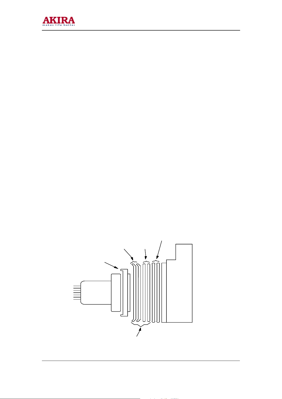
2. Insert six-row-wire into CN002. Press adjustment keys and then go to automatic white balance
adjustment.
3. PIN DISCRIPTION OF CN002:
1●●SDA●●2●●SCL●●3●●GND●●4●●GND●●5●●SCL●●6●●SDA
4. After adjust well, pull out six-row-wire.
White balance adjustment (Applied when servicing)
1. Set TV AV status and receiv GREY SCAL.
2. The one sampling tube of CRT color analyzer (CA-100) covers on GREY signal and the another
covers on white signal.
3. Go to factory mode MENU2. Obtain GREY signal X=281 and y=311 by adjusting R-CUT and B-
cut. Obtain white signal X=281 and y=311 adjusting R-DRV and B-DRV. Obtain both X=281 and
Y=311 by adjusting the two status repeatedly.
Sub_Bright adjustment
Receive the grey scale. Get into the menu5 of factory mode. Set SUBB.ADJ to 1. Then adjust the
SUB.BRI option to get a scale to be seen a little brightness (only two rows can be seen).
Vertical size and Pin Cushion adjustment
1. Receive monoscope pattern. Set TV standard status. Adjust V.size to obtain pictures vertical
redisplay ratio mode than 90% in factory mode MENU1.
2. Receive cross hatch pattern. Set TV standard status. Adjust V.LINE and V.SC to obtain picture
vertical pin cushion a good status in factory mode MENU1.
3. Receive cross hatch pattern. Set TV standard status. In factory mode MENU1 adjust V.POS to
obtain pictures vertical center at the center of CRT screen.
Horizontal Center adjustment and horizontal position of OSD adjustment
1. Receive monoscope PATTERN. Set TV standard status. Adjust H.PHASE in menu 1. to obtain
horizontal center at the center of CRT screen.
2. Adjust OSD.HPOS to get right display position.