5
Model No: CT-21LPS1MKI-ANZ
Version 1.0
GENERAL DESCRIPTION
AKTP01/02 chassis series are applied A14T02/A14T02a respectively which uses mainly TOSHIBA’
advanced UOC-ultimate chip TMPA8803/8821/8851 and I2C-bus controlled IC with combination of
micro controller and small signal processor, the TMPA8803/8821/8851 series feature high-integration,
high performance-to-price ratio and high-reliability and advanced functions with fewer external
components, which provide much convenience for manufacturing and technical service.
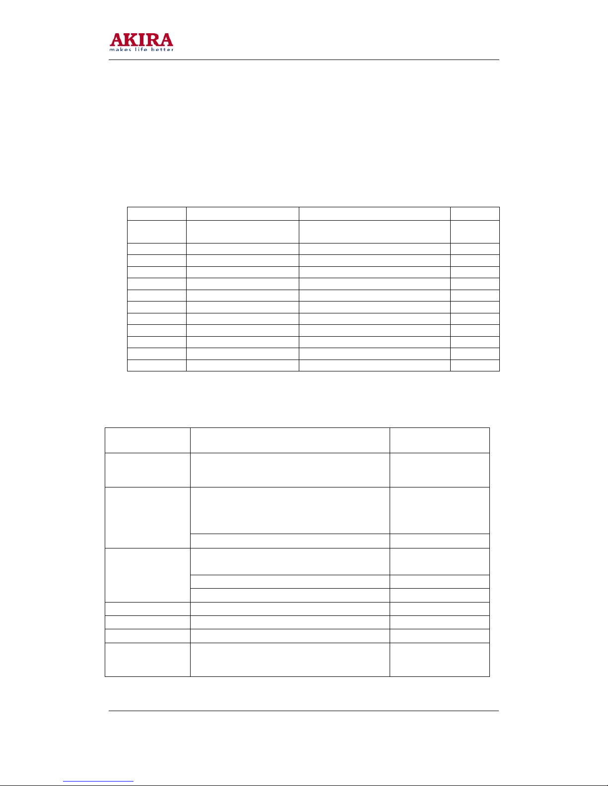
Table 1: A14T02 mainly ICs and functions
Position Type Function Description Remark
N204 8851CPNG6EG1 Micro controller and small signal
processor (UOC)
V501 Driver Transistor (C4460) Power Supply
T501 BCK-65-10 D3 Isolate Transformer
A101 ET-5C1E-EV200K Tuner
T402 BSC25-05N2135 FlyBack Transformer
N701 TA1343NG Sound Processor
N702 TDA7496SA Sound power amplifier
N402 STV9302 Vertical Scan Output Stage Circuit
V411 TT2496 Horizontal Driver TST
N901 ATMEL 24C16 EEPROM IC
Z101 K2955 Saw Filter
N203/N207 TC4053 AV1/AV2 Switch
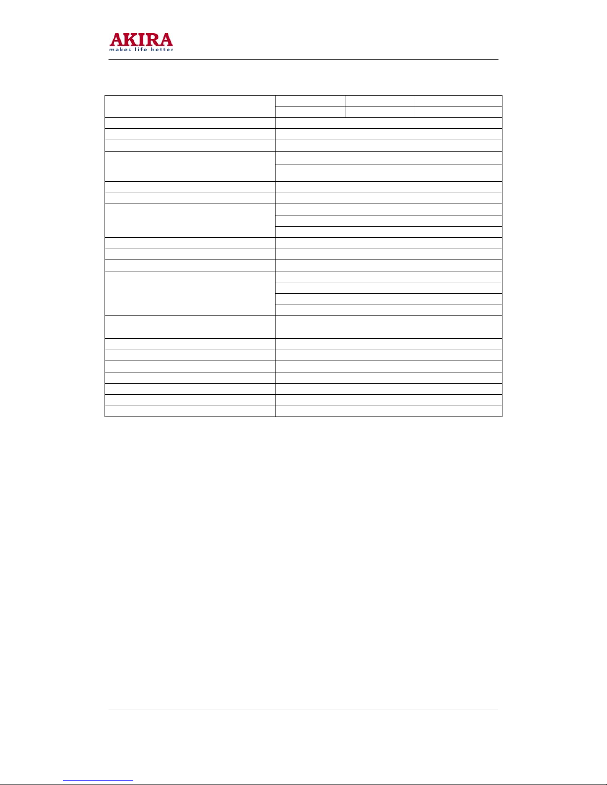
TECHNICAL SPECIFICATION
Test Item Conditional TD171
AC Operating
Range
RF&AV signal input with sound loud speaker
(volume maximum) & Picture set in Dynamic
mode 115Vac ~ 240Vac
Philips or Mono-scope pattern signal with howling
sound Contrast & Brightness set in Maximum,
sound increase maximum 100Watts
Total Power
Consumption
Standby Mode 14 Watts
Brightness & contrast set in Maximum Min: 26.2KVdc
Typical Design value Average: 26.5KVdc
EHT
Brightness &contrast Minimum Max: 27.8KVdc
Anode Current Brightness &contrast Maximum IABL = 1.08mA
Heater Voltage TV operate normally V Heater = 6.2Vac
B+Normal operating VB+= 112Vdc
Sound power
output
RF signal input broadcasting at
217.25MHz/BG/DK(1KHz)
Volume is maximum
V = 9.2Vrms
P = 10Watts X 2