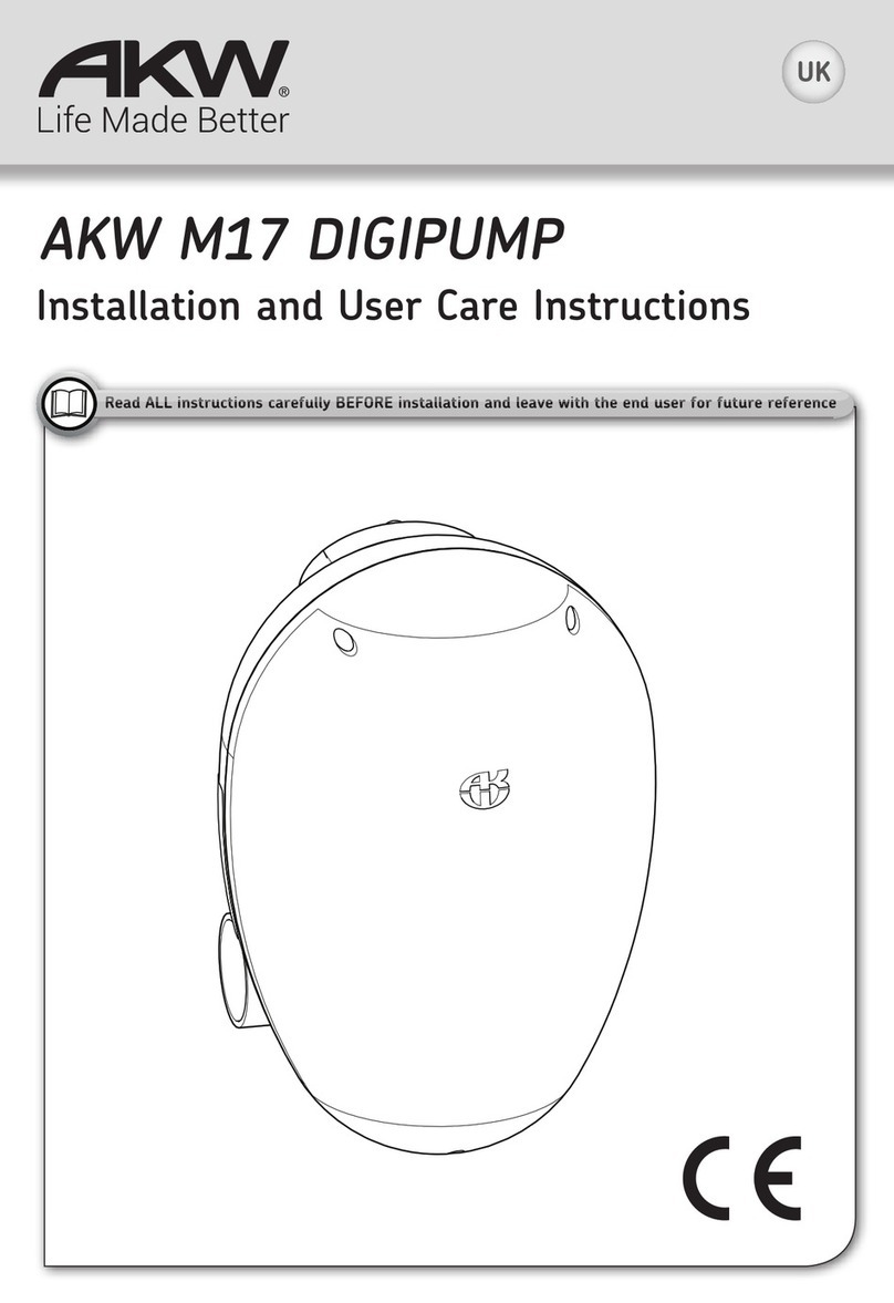
Akw M11 DigiPump Installation guide

AKW M11 DigiPump
Installation and User Care Instructions
UK
EU Reg Des:
000717541-0001/2/3
GB and World-Wide
Patents Pending
Read ALL instructions carefully BEFORE installation and leave with the end user
R d ALL i t ti f ll BEFORE i t ll ti d l ith th d
Electric or Mixer
Shower Shower
Quantities depend on type of
Shower kit and waste ordered.
1x 1x
1x 1x
6x 10x
3x 3x
1x 2x
1x 2x
2x 4x
2x 4x
The following items are NOT
required or included if an AKW
shower interface is to be installed:
Box contents for
1x 15mm
1x 22mm

Contents Page
Product Specifications-Declaration of Conformity 2
Important Safety and Electrical Information 3
Mechanical and Plumbing Installation 4-6
Fixing pump to surface 7-8
Plumbing connections 9
Fitting Flow Sensor(s) 10-11
Electrical Installation 12-13
Pump Set Up 14
Commissioning 15
Care and Maintenance 16
Problem Solving 17
WARRANTY 19
PUMP CAPACITY - 11 LPM MAX under free head/lift conditions
Derate accordingly for installed conditions.
Max Head: 1.0m (39in).
Max Lift: 0.5m (19in).
MAX COMBINED HEAD + LIFT:1.5m (59in)
SUPPLY: 230V AC 50Hz 73W
T5A fused internally
DUTY CYCLE: 30 mins max on 50% duty
Quiet in operation.
For use with compatible electric or mixer showers.
Pump and controller enclosed in one unit.
Max flow rate: 11 Litres Per Minute (LPM).
Non-handed, selectable inlet/outlet direction.
Note: Increased Head/Lift conditions will affect the pump’s performance.
AKW M11 DigiPump high performance shower waste water pump.
Product Specifications
Declaration of Conformity
We declare that the AKW M11 DigiPump shower waste water pump conforms to the
requirements of the EMC Directive 89/336/EEC, Low Voltage Directive 73/23/EEC and the
following harmonised European and national standards in the confirming assessment.
BS EN 61558-1, BS EN 61558-2-6, BS EN 60335-1, BS EN 60529,
BS EN 60335-2-41
AKW Ltd
KM507429
2

Important Safety/Electrical Information
Ensure Mains Power Supply is Switched OFF before starting wiring.
The 230V AC power supply to this unit must be provided via a two-pole isolator
switch and a dedicated circuit with a 30mA RCD device installed in accordance
with the latest revision of the IEE Wiring Regulations BS7671. It must be wired into
a fused, unswitched, fixed wiring connector fitted with a 5 amp fuse.
The IP45 rating of the AKW pump product refers to the inner casing containing the
SELV electrical control gear. The pump motor which operates at SELV and is
located within the outer cover.
DO NOT take risks with Plumbing or Electrical Installation. This product
must be installed and serviced by a competent and qualified person eg.
NIC EIC trades person should attempt this electrical installation in
accordance with the current edition of the Wiring Regulations (BS7671),
local by-laws and the current Building Regulations.
This product must be installed, used and maintained in good working
order in accordance with these instructions and recommendations.
THIS CLASS II APPLIANCE DOES NOT REQUIRE AN EARTH
Caution Danger of Death 230V AC
Lethal Voltage present on the AC supply.
3
If the supply cord is damaged, it must be replaced by the manufacturer
in order to avoid hazard.
ò+YPSS)P[Z
ò:\P[HISL^HSSWS\NZ
ò:JYL^KYP]LYZ
ò:WPYP[3L]LS
ò7PWLJ\[[LYZ1.;:
òTT7PWLHUKTT7PWL
ò1VOU.\LZ[SVJRPUNJVSSHYZ
Before you start... Confirm you have the required tools and parts.
Standard JG pipe connectors ARE NOT SUITABLE for connecting to
CHROME or STAINLESS PIPEWORK.
Chrome plating must be completely removed 20mm before JG fittings are
connected to pipework.
Always use Collet Clips provided to ensure maximum grip.
It is not possible to connect JS fittings to Stainless Steel Pipe.
(2>9LJVTTLUK[OL\ZLVMH1VOU.\LZ[JOYVTLWPWLHKHW[VYWHY[UV

Mechanical And Plumbing Installation
Positioning
© 2012 AKW Limited
The AKW M11 DigiPump shower waste water pump must be installed by a
suitably qualified, competent person eg. NIC EIC, in accordance with current IEE
Wiring Regulations (BS7671), building regulations and local by-laws.
This product is rated at IP45 and suitable to be installed in Zone 1 or Zone 2
of a shower room only if these instructions are fully complied with.
The unit must be located away from the direct line of water jets.
Note: Zone 1 lies above zone 0 and below 2250mm (88in) vertically above a shower
tray or wet floor area.
The perimeter of zone 1 of a wet floor is within a 1.2 metres (47in) radius of the
shower head position. Consult BS7671 for further clarification.
4
FOR GUIDANCE ONLY- PLEASE REFER TO BS7671 FOR FURTHER DETAILS

Electric Shower Installation
15mm Pipework to Pump Inlet 22mm Outlet
Pipework
DigiPump
DigiPump
Fit two Flow Sensors. One to hot
and one to cold water-feed pipes
Fit one flow sensor to cold
water-feed pipe
230V AC
Supply
Note: REMOVE ALL BUILDING RUBBISH FROM TRAY
Otherwise you will be called out again to clear pump blockages!
Fit Strainer before Sensor
Mixer Shower Installation
230V AC
Supply
Fit Strainer before Sensor
5
12V DC
Sensor Cable
Flow Direction
Flow Direction 12V DC
Sensor Cable
22mm Outlet
Pipework
15mm Pipework to Pump Inlet
Ensure all cables
and plumbing
are behind water
resistant surface.
Cable routing and
separation must
conform to wiring
Regs BS7671.
Ensure all cables
and plumbing
are behind water
resistant surface.
From Flow Sensor
or compatable
electric shower.
Cable routing and
separation must
conform to wiring
Regs BS7671.
Ensure Sensor(s) and
Strainer(s) are in an easily
accessible location.
Ensure shower water supply
pipework is flushed before
connecting to the shower
sensor via the strainer.
Ensure Sensor and
Strainer are in an easily
accessible location.
Ensure shower water supply
pipework is flushed before
connecting to the shower
sensor via the strainer.

Do NOT use damaged pipe Do NOT use Speedfit
®pipe inserts on low
pressure lines as they create blockages
DO Cut plastic pipe using a pipe cutter Do NOT use a hacksaw to cut plastic pipe
Pipe Cutter
JG TS
Speedfit
Pipe
Note: 1.707,*655,*;69:(9,56;:<0;()3,-69*655,*;065>0;/*/964,69:;(053,::
PIPEWORK. Remove any chrome plating on pipework of at least 20mm before inserting this type
VMWPWLPU[V1.MP[[PUNZ
(2>9LJVTTLUK[OL\ZLVMH1VOU.\LZ[JOYVTLWPWLHKHW[VYWHY[UV
6
For Optimum Performance
Important: For service & maintenance purposes this product must be installed in an
accessible location.
Pipe connections must be easily accessible and a clearance of 100mm around the
base and sides is recommended.
Fixing pump to surface
100mm (4in)
The pump unit must be located on a vertical surface with the
inlet/outlet connections at the bottom of the unit in horizontal
alignment, with the AKW case logo uppermost.
The unit must be located away from the direct line of water jets whenever possible.
DO NOT tile up to the pump unit on the wall, only fix onto surface.

Remove front cover
with a screwdriver.
Disconnect cable.
Remove pump assembly
from the back plate to
access the fixing holes.
Fit to a finished surface.
Do not tile up to Pump
case.
Using the back plate as a
template mark the fixing
holes. Drill and plug the
wall taking care there are
no hidden cables or pipes.
Use all the screw fixing
positions.
1
2
3
7
Fixing pump to surface
Mount the pump to the
finished surface using all
the wall fixings.
Use the Pump Spacers to
prevent the cables being
trapped.
See pump spacers
installation instructions on
page 13.
4

Check that the flow is in the required direction, reverse as required.
Loosen the pump head housing, rotate and fully tighten home.
The pipework to this high performance pump must be clamped down effectively-
AKW advise and recommend you clamp pipework either side of joints, junctions or
connections and at a maximum of 500mm between other supports
REMOVE SHIPPING
TAPES from ends.
Refit the pump to the
back plate.
Reconnect cable.
Refit the front cover.
5
6
8
8
Fixing pump to surface
Fit the pump connectors
to the pump. Note 15mm
connector for the inlet.
Screw both ends into
place. No thread sealant
needed, firmly hand
tighten only.
7
Check that you have not overtightened and
distorted the valves before connecting the pipework.
Fully tighten
Flow direction
from the front.
Insert Insert
Rotate to direction of flow
Loosen

Plumbing Connections
MIN
HEAD
LIFT
HEAD
Shower Head
Waste outlet
pipe
NOT PREFERRED PREFERRED (NO ELBOWS)
Shower Tray
This AKW M11 DigiPump is rated for:
Max Head: 1.0m (39in)
Max Lift: 0.5m (19in)
Combined Lift and Head: 1.5m (59in) MAX.
For best performance locate within 1m (39in) of shower
and minimise the number of lifts, bends and the length of
all pipes connecting the Pump to the waste outlet pipe.
Note: Increased Head/Lift conditions will affect the pump’s performance.
Important: For service & maintenance purposes this product must be installed in
an accessible location. Pipe connections must be easily accessed.
Important: All external pipe connections must be at least 100mm (4in) clear and
suitable for pump removal.
1VOU.\LZ[sHUK:WLLKMP[sHYLYLNPZ[LYLK[YHKLTHYRZVM1VOU
Guest International Limited.
5,=,9MP[1VOU.\LZ[®Pipe inserts. ALWAYSMP[1VOU.\LZ[®locking collars.
9
MINIMISE PIPEWORK LENGTH WHEREVER POSSIBLE
OR
100mm (4in)
MIN GAPS
Use the supplied Pipe
Adaptors to connect
to waste outlet pipe.

The electric shower has one supply line – cold water – fit one flow sensor to this line.
Install the filter which is a Y-Pattern strainer, in the correct position to the shower water supply
line and then fit the flow sensor between the filter and the shower heater.
Failure to install the Strainer may invalidate any warranty for the product.
Fit sensor using an approved liquid based thread sealant suitable for nylon threads.
FILTER IN WRONG POSITION
10
CORRECT
POSITION
WRONG POSITION
Strainer
Sensor Tail
Sensor Cable
JG Push-Fit
Shower
CORRECT POSITION
Strainer
Sensor Cable
Flow
Direction Shower
Confirm shower water supply pipework is
flushed before connecting to the shower
sensor via the strainer.
Any building debris in the water supply to the shower
heater will adversely affect the sensor function and
may also damage the shower heater.
All cable connections must be in a dry location. DO NOT tile over Flow Sensors.
Flow
Direction
CHECK FLOW SENSOR DIRECTION
Fit Flow Sensors between the
strainer and shower.
Allow enough distance so that the
sensors are easily accessible.
Flow Sensor
Check Flow Direction
DO NOT tile over Flow Sensors
They must be accessible for servicing
CHECK FILTER POSITION
Flow Sensor
CHECK: Direction of flow arrow moulded on casing is in the correct orientation.
Connect the sensor cables from the flow sensor to the pump (see electrical installation).
Ensure sensors and strainers are accessible for service and maintenance purposes.
Flow
Direction
Flow
Sensor
Direction
Flow
Direction
Vertical Cold Water Feed
Horizontal Cold Water Feed
Fitting Supply Flow Sensor To Electric Shower

Fitting Supply Flow Sensor To Mixer Shower
Fit Flow Sensors between the
strainer and shower.
Allow enough distance so that
the sensors are easily accessible.
The Mixer shower has two supply lines – hot and cold water– fit one flow sensor to each line.
Install the filter which is a Y-Pattern strainer, in the correct position to the shower water supply
line(s) and then fit the flow sensor between the filter and the shower heater.
11
Flow
Direction
Shower
JG Push-Fit
Sensor Tail
CORRECT
POSITION
WRONG POSITION
CORRECT POSITION
Failure to install the Strainer may invalidate any warranty for the product.
Fit sensor using an approved liquid based thread sealant suitable for nylon threads.
Flow Sensor
Check Flow Direction
Sensor Cable
Shower
Strainer
All cable connections must be in a dry location.
Confirm shower water supply pipework is
flushed before connecting to the shower
sensor via the strainer.
Any building debris in the water supply to the
shower heater will adversely affect the sensor
function and may also damage the shower
heater.
DO NOT tile over Flow Sensors
Sensor Cable
CHECK FLOW
SENSOR DIRECTION
FILTER IN WRONG POSITION
Flow
Sensor
Direction
Flow
Sensor
Direction
They must be accessible for servicing
CHECK FILTER POSITION
Flow
Direction
CHECK: Direction of flow arrow moulded on casing is in the correct orientation.
Connect the sensor cables from the flow sensor to the pump (see electrical installation).
Ensure sensors and strainers are accessible for service and maintenance purposes.
Strainer
Flow
Direction
Flow
Direction
Vertical Hot & Cold Water Feed
Horizontal Hot & Cold Water Feed

Electrical Installation
Ensure Mains Power Supply is Switched OFF before starting wiring.
The AKW M11 DigiPump shower waste pump must be installed in accordance with the current IEE wiring
regulations (BS7671) and local by-laws. NIC EIC recommended.
This product is rated at IP45 and may be installed in Zone 1 of a shower room only if the following
conditions are fully complied with:
DO NOT take risks with Plumbing or Electrical Installation.
Only a competent trades person should attempt this installation.
The pump unit must be located on a vertical surface with the inlet/outlet connections at the bottom of the
unit in horizontal alignment, with the AKW case logo uppermost.
The unit must be located away from the direct line of water jets whenever possible.
Cable to and from the pump must be run directly out of zone 1 by the shortest route below the unit or
directly behind into the vertical surface. All such routes must be sealed to prevent water ingress.
Cables routed from above, down into the device, act as a drip path and should not be used.
Cables must be protected against mechanical damage and sealed against water ingress.
The case must not be cut except for the thin rear shroud. Do not pierce casing.
The clearance behind the unit and separation from the wall must be maintained and the gap from case to
wall must not be sealed.
The Pump Spacers kit supplied can be used to route the cables behind and below the unit if required.
All casing cable glands must be visually checked for presence of the elastomeric centre sealing grommet and
tightness checked and confirmed before installing against the wall.
No cable joints may be made in zone 1.
The unit inner cover must not be disturbed and the outer cover must be correctly fitted.
The 230V AC power supply to this unit must be provided via a two-pole isolator switch and a
dedicated circuit with a 30mA RCD device installed in accordance with the latest revision of the
IEE Wiring Regulations BS7671.
It must be wired into a fused, unswitched, fixed wiring connector fitted with a 5 amp fuse.
The IP45 rating of the AKW pump product refers to the inner casing containing the SELV electrical control
gear. The pump motor which operates at SELV 24V DC (maximum) is located within the outer cover.
12
Mains supply
13amp rated
double pole
isolating switch
Sensor
cable
Flow Sensor
Isolating valve
THIS CLASS II APPLIANCE DOES NOT REQUIRE AN EARTH
45amp double pole
isolating switch
Consumer unit
containing
30mA RCD
Electric shower installation schematic
M11 DigiPump

Flow Sensor Connection
Flow sensor
cables Power cable
13
Pump
Spacers
Pump spacer connection
Seperate the spacers, remove the adhesive backing and snap into position.
Only remove the
adhesive tab at this
hole.
Any unused sensor wires must be terminated in a connector block and insulated using electrical insulation
tape at a dry location. Failure to do this may damage the pump.
Ensure the pump spacers are used to prevent the cables from being trapped.
Red
Brown
Flow Sensor
Wire +
SBlack
White
Red
Black
Pump Wire
Connector Block
+
S
-
Red
Brown
Black
Connects to
Connects to
Connects to
Red
White
Black
Flow Sensor Pump
All cable connections must be in a dry location.
CONNECTING FLOW SENSOR TO M17 DIGIPUMP
To connect the flow sensor cable directly to a compatible electric shower please see the
instructions supplied with your electric shower.
CONNECTING FLOW SENSOR TO COMPATIBLE SHOWER

Test
When power is supplied to the pump the upper run LED (yellow) should glow indicating a voltage present,
and the digital display will show the run on timer setting in seconds (factory set is 20).
Press the TEST button. The digital display will show the start delay in seconds (factory set is 5) and the
bottom LED will flash and start the following test sequence:-
Test sequence once button is pressed
1. Start delay timer counts down. (bottom LED flashing)
2. The pump runs with top LED flashing and the display shows the time to run.
3. The display returns to the set run on time.
This test can be carried out with or without water present and also the sensor fitted or not.
Calibration
The AKW M11 DigiPump allows for precise pump control of the shower water by calculating the amount
of water the shower is producing. It may be necessary to adjust the pump once installation is complete.
(the pump may be over or under pumping).
To calibrate the pump and compensate for this, press and hold the TEST button for around 5 seconds,
until both LEDs flash. The pump is now in calibration mode. The display shows the factory calibration value
stored (default is 50).
This can be adjusted using the RUN button (up) and the DELAY button (down). The value can be adjusted
from 0-99.
Run the shower at the expected normal flow rate. The pump must run at a speed which removes the same
amount of water as is flowing in.
Adjust the calibration value so the water level stays approximately the same. If the water level drops,
decrease the value on the display so the pump runs slower. If the water level rises, increase the value on
the display so the pump runs faster. When the value is set correctly, press the test button to store. The
controller will then return to its normal operating mode.
Timer Adjustment
With the pump in normal operating mode and the LED showing the run on time:
Adjust Run on time. (the time the pump will run after the shower has stopped)
Press the RUN button: this will increase the time by 1 second, holding the button will increase the time
rapidly, once the time reaches 99 it will roll over to 01.
Start Delay (the time before the pumps starts after the shower is operating)
Press the DELAY button: this will increase the time by 1 second, holding the button will increase the time
rapidly, once the time reaches 99 it will roll over to 01.
Pump set up
Control Button Description
Top Button = RUN (Sets shower stop run-on time)
Centre Button = TEST (Calibration)
Bottom Button = DELAY (Sets shower start delay to run)
14
M11 Pump Calibration is only to be carried out by a suitably competent trades persons to prevent the
risk of future adjustments causing flooding.

Commissioning Checks
As a general precaution and check before installation, always ensure the supply pipework to
the shower has been fully purged with at least 20 litres (2 buckets) of water through it before
the flow sensor or shower water heater are fitted. Any building debris in the water supply to the
shower heater will adversely affect the sensor function and may also damage the shower heater.
Install Pump according to these instructions. Failure to do so will void warranty.
Confirm all push-fit pipes are fully inserted 20mm into fittings.
Brush out all dust, grit and debris
from shower tray
Thoroughly clean out waste
Confirm shower water supply pipework is flushed
before connecting to the shower sensor via the
strainer
Turn on power to Pump
Turn shower on Low Flow and confirm pump
operates after approx 5 secs. Run for 2-3 mins
Set shower to Maximum Flow
Follow the Calibration setting, adjust pump speed
on controller to match maximum shower flow
Adjust RUN-ON and repeat until tray is cleared
and pump stops with minimum RUN-ON
Switch shower OFF.
Pump will RUN-ON
If you experience problems see
Problem Solving section
15

Problem solving
Please refer to pump instructions to ensure the pump is installed
correctly.
PUMP WILL NOT START
Ensure flow sensor is connected to pump controller and power is
on to pump controller.
Ensure that all pipe work is fully flushed before the flow sensor is
installed, and the in-line strainer is in place.
Check flow sensor is installed in right orientation
(Flow direction arrow moulded on the casing).
Most flow sensor problems are due to debris being caught inside
the flow sensor. Remove sensor and check for debris.
If required reverse flush with water.
Care and Maintenance
The integrity of the case and the RCD device operation must be checked quarterly
as part of a routine safety and maintenance activity on the installation.
If the case shows any mechanical damage the unit must be isolated electrically and
the entire unit replaced.
Pipework connections must be made to the unit with sufficient clearance (100mm
minimum separation to any pipe bend or fitting adjacent to the inlet/outlet
connections) to permit removal of the pump/head for routine maintenance and
replacement.
The unit must be regularly cleaned using normal bathroom cleaning materials and
rinsed down with clean water and wiped dry with a soft cloth to remove any cleaning
residue.
Do not use strong or concentrated acidic or alkaline cleaning materials as these may
discolour or otherwise damage the product. Do not use an abrasive cloth.
16

PUMP WILL START
BUT NOT PUMP WATER
PUMP WILL NOT STOP
Check Non-Return Valves are
fitted in inlet and outlet.
The pump has an overrun timer to allow it to continue to run after the
shower has been switched off. This timer is factory set to 20 seconds.
With the power supply switched on, disconnect the flow sensor. Separate
the disconnected wires. This will simulate the flow sensor turning off.
Pump should stop after the overrun time. If not, check the controller
display panel or cabling. If the pump has not stopped, disconnect power
supply and contact customer services.
If controller is OK, remove and check the flow sensor, flush it through with
water or replace it as necessary.
When increasing the pump speed*, if the pump still performs low or no
suction, take off the pump head by removing the clamp ring. Examine the
inlet and outlet flap valves for traces of hard debris such as grit.
If so, wash out all debris and ensure the
valves are seated correctly.
If problem persists, check all connections for air leaks or blockage in
either the inlet or outlet pipework. Repair any leaks or clean blockages.
Confirm plastic pipe inserts are
NOT used.
(see page 1 of instructions)
Ensure all push-fit pipe connections are fully sealed and O-rings are not
damaged or displaced.
The water pumping capacity can be adjusted by adjusting pump speed.
Adjust pump speed using the calibration setting.
Please refer to instructions overleaf
Problem solving
* Please See Pump Set Up
17

Warranty Registration Details
To be completed by Installer
INSTALLED ON ______/______/_______
INSTALLED BY _______________________________________________
ADDRESS ____________________________________________________
____________________________________________________
____________________________________________________
CONTACT ____________________________________________________
____________________________________________________
Product Identification label can be found on the pump case and also on the outer
packaging.
Model / Part Number __________________________________________
Serial Number (SN) ____________________________________
Batch Number (BN) ___________________________________________
IMPORTANT: TO ACTIVATE YOUR WARRANTY PERIOD
YOU MUST REGISTER YOUR PRODUCT WITHIN 30 DAYS!
FREE 5-YEAR WARRANTY OFFER
To register for your free 5 year warranty please return
the registration card within 30 days of installation.
Registration is optional but you will only receive this
5-year extended warranty if you register.
Your statutory rights are not affected
Please complete the registration card within 30 days and return to us in the prepaid envelope for your Free Warranty to start.
Product Identification label

This warranty is in addition to your statutory and other legal rights.
To validate and start the warranty, you must return your completed registration card
in the prepaid envelope for your warranty to start.
AKW Ltd warranty Covers your shower waste water pump against any defect in
materials or workmanship for 5 years from the date of installation. Within this period
we will resolve defects free of charge by repairing or replacing as we may choose.
To be free of charge work must only be undertaken by AKW or our approved agents
in the UK or the Republic of Ireland and with prior agreement.
Any action taken under this warranty does not extend the stated 5-year expiry date.
NOT COVERED BY THIS WARRANTY
Damage or defects arising from incorrect installation, improper use, lack of
maintenance including debris & blockages, build-up of limescale or any
unauthorised modifications.
Actions taken to dismantle, repair or modify beyond that shown in this installation
guide, by persons who are not AKW Ltd authorised service staff or agents.
Damage resulting from water freezing.
BEFORE USING YOUR SHOWER WASTE PUMP
Please take time to read and understand the operating and safety instructions
detailed in this manual.
WHAT TO DO IF SOMETHING GOES WRONG
If your shower does not work correctly first follow the Problem solving chart on
page 16, then contact your installer.
Should this not resolve your problem, contact AKW Customer Services who will
provide further advice and if necessary arrange for our service engineer to visit, or
discuss our comprehensive after-sales service. As part of our quality and training
program calls may be monitored or recorded.
None of the forgoing affects your statutory rights.
WARRANTY
As part of our on-going improvement programme, AKW would appreciate any
feedback on these instructions.
If you have any comments please contact us on Tel:+44 (0) 01905 823235

Failure to install this AKW product in accordance with supplied instructions or the making of
unauthorised modifications will invalidate any warranty and will affect product safety.
Post
AKW, Pointon Way, Hampton Lovett,
Droitwich Spa, WR9 0LR
Contact Information
Orderline
01905 823299
General Enquires
01905 823298
Technical Help line
01905 823242
Fax
01905 823297
Website
www.akw-ltd.co.uk
Enquires email
Quotes & orders email
DANGER OF DEATH!
230V AC
Lethal Voltage present on the AC
supply to the pump inner case.
This unit must be connected to
a double-pole switched supply,
suitably fused and provided with a
RCD protection.
This product must be
installed by a qualified and
competent electrician and
in accordance with the current
edition of the Wiring Regulations
BS7671. This appliance must be
located to comply with the safety
zones as defined in the wiring
regulations.
Isolate this unit before access for
maintenance or any other purpose.
Do not immerse in water.
No USER serviceable parts within
case.
The cover must only be removed
by an authorised service person or
electrician.
Important
Safety
Information
© 2012 AKW 07-001-196-01
Table of contents
Other Akw Water Pump manuals
Popular Water Pump manuals by other brands

Annovi Reverberi
Annovi Reverberi AR 160 LFP instruction manual

Ingersoll-Rand
Ingersoll-Rand 66243-X Operator's manual

Graco
Graco 224667 Instructions and parts list

AquaScape
AquaScape AquaSurge 2000-4000 Instructions & maintenance

Mitsubishi
Mitsubishi PAC-KE07DM-E installation manual

SCINTEX
SCINTEX SPS240VADEF user manual

Pulsafeeder
Pulsafeeder PulsaPro PP680 Installation, operation & maintenance manual

CET
CET PFP-27hp-HV instruction manual

Caffini
Caffini LIBELLULA 2" Series Use and maintenance instructions

Proxxon
Proxxon AP 12 manual

Grundfos
Grundfos ALPHA2 Series Installation and operating instructions

Grundfos
Grundfos Unilift AP12 Installation and operating instructions