AL Tech CB6012A User manual

Page 1
Thank you for choosing one of our products for your work.
We are certain that it will give the utmost satisfaction and be a notable help on
your job and application.
Product Description
The Smart Battery Charger CB60 is available in two versions: 12V 5A and 24V
3A (5A Max). The CB60 series is a family of battery chargers based on the
"Switching technology" and "Battery Care philosophy" that have been part of
Adel System's know-how for 30 years. This experience has led to the
development of this advanced multi-stage, fully automatic battery charger,
which is suitable for meeting the most advanced requirements of battery
manufacturers. The Battery Care concept is based on algorithms that implement
fast and automatic charging, optimization of battery charging during all charging
stages, recovery of discharged battery, and real-time diagnostics during
installation and operation. The real-time diagnostics system discreetly monitors
the battery and detects its faults, such as shorted elements, accidental reverse
polarity connections, battery disconnection, and incorrect voltage. Such faults
are indicated by intuitive flashing of the diagnostic LED. Each device is suitable
for all battery types: default curves can be set for open lead-acid, AGM, Gel and
NiCd batteries. A rugged enclosure with bracket for DIN rail and wall mounting
provides IP20 protection.
1 Safety and warning notes
WARNING – Explosion Hazard. Do not disconnect equipment
unless power has been switched off or the area is known to be non-
hazardous.
WARNING – Explosion Hazard. Substitution of components may
impair suitability for class I, Division 2.
WARNING – Switch off the system before connecting the module. Never work
on the machine when it is live. The device must be installed according to
EN61010 or EN62368-1. It must be possible to disconnect the device with a
suitable isolating facility outside the power supply unit. Danger of fatal Injury!
WARNING – The device is equipped whit an internal fuse. If the internal fuse
blows up (fails opens) most likely there is a fault in the device. If this failure
occurs, the device must be returned to the factory.
2 How to Install
Mounting
Fig. 1 – Drawing of the CB60 series battery chargers
Din Rail or Panel Mounting
Fig. 1 shows a dimensional drawing of the CB60. It is possible to mount the
device on Din rail or panel and fix it by 2 screws 2.9x8-16. There is no limit to
the Panel thickness.
How to Supply the device
The CB60 battery chargers have a single-phase input and can operate in the
range 90 to 305 VAC; therefore, they are suitable for standard 110, 230 and 277
VAC systems.
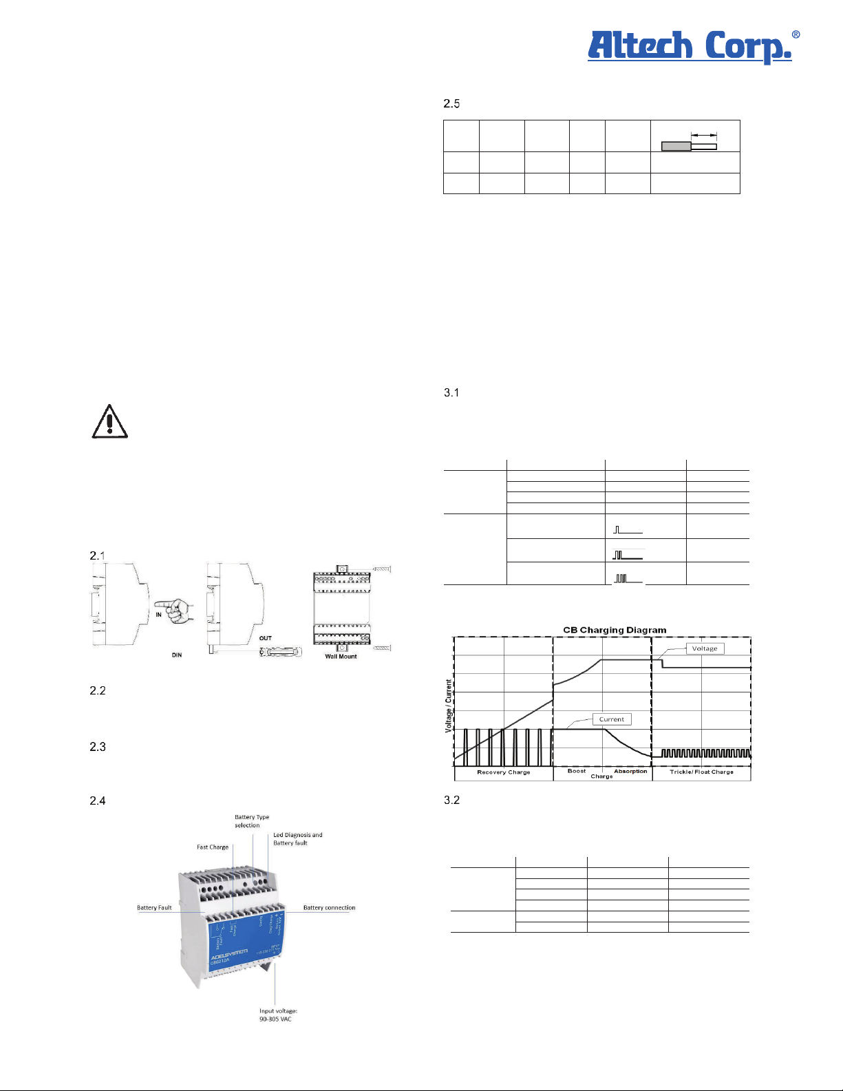
Device Connection (Fig.2)
Connection terminal and wiring
The following cable cross-sections may be used:
Solid
(mm2)
Stranded
(mm2) AWG Torqu
e (Nm)
Stripping Length
In: 0.2 –
2.5
0.2 –
2.5
24 –
14
0.5 –
0.6 Nm
7 mm
Out: 0.2 –
2.5
0.2 –
2.5
24 –
14
0.5 –
0.6 Nm
7 mm
Screw type terminal block, 2.5 mm2. Wiring terminal shall be marked
to indicate the proper connection for the power supply. For supply connections
use copper cables only, use wires suitable for at least 75°C.
3 Functionality
The CB60 battery chargers implement a multi-stage battery charging technique
to ensure optimal battery performance and health. An additional feature, the
power function, can be activated via the user interface and allows the output
voltage to be available even when the battery is not connected. Otherwise, when
the battery is not connected, the battery output terminals of the CB60 are devoid
of voltage.
The user interface of the CB60 charger consists of a button and a multicolor
LED. It shows the activity of the device and allows you to view and change the
configuration of the device. By default, the CB60 is configured to operate with
an open lead-acid battery and the power function is disabled.
Charging
The normal indication of the user interface: when the battery is charging, the
device signals the charging phase with a continuous GREEN flashing, with a
frequency that depends on the charging phase in progress. Conversely, if a fault
is active, the device displays a sequence of ORANGE flashes followed by a
pause.
Device status State LED Diagnosis LED Color
Charging
Recovery 5 blinks / sec Green
Bulk 2 blinks / sec Green
Absorption 1 blink / sec Green
Float 1 blink / 2 sec Green
Auto Diagnosis
Fault
Reverse polarity or
wrong battery voltage
1 blink / pause Orange
Battery not connected 2 blinks / pause Orange
Battery with shorted
cells
3 blinks / pause Orange
Table 1 – LED signaling and the corresponding device activity
Type of charging it is current-limited and constant-voltage, IUoU profile in
conformity to DIN41773.
Displaying the current device configuration
While the user interface is showing the device activity, press briefly (less than
1sec) the pushbutton to display the Battery Chemistry. The device will display
the chemistry by means of a number of GREEN LED blinks followed by a pause,
immediately followed by the Power Supply configuration enabling status, by
means of a number of RED blinks followed by a pause, according to Table 2:
State / Type LED Diagnosis LED Color
Chemistry
Open Lead 1 blink / pause Green
AGM Lead 2 blinks / pause Green
GEL Lead 3 blinks / pause Green
NiCd 4 blinks / pause Green
Power supply
function
Disabled 1 blink / pause Red
Enabled 2 blinks / pause Red
Table 2 – Device configuration display and program
The user interface then automatically resumes the normal display of device
activity. The ongoing battery charging process is not interrupted or affected in
any way during the device configuration display.
Altech Corp.® • 35 Royal Road • Flemington, NJ 08822-6000 • P 908.806-9400 • F 908.806.9490 • www.altechcorp.com
Instruction Manual
CB6012A and CB6024A
Battery Charger

Page 2
Programming the device configuration:
Note that device programming is possible only after the device is turned on,
when the battery is not connected. While the user interface shows device
activity, to enter programming mode, press the button for more than 2 seconds
until the LED flashes ORANGE. When you release the button, the LED flashes
once in GREEN followed by a pause. This means that the battery chemistry is
open lead. Press the button repeatedly to scroll through the chemistries to the
desired one-the LED displays a number of GREEN flashes corresponding to the
chemistry according to Table 2. Confirm by pressing the button for more than 2
seconds when the desired chemistry is displayed. The LED flashes GREEN to
indicate that the chemistry has been tentatively set. Note that the chemistry
must be selected: a short press of the button when NiCd is displayed will restart
the chemistry selection from Open Lead. After confirming the chemistry with a
long press, the enabling state of the power function can be selected with the
same logic, except that the LED will flash RED. When the desired option
(enabled or disabled) is displayed, long press the button to confirm the
selection-the LED will flash RED for confirmation.
When programming is completed, the device summarizes the new
configuration as described in "Displaying the current device configuration,"
then resumes the normal display of device activity.
NOTE that the entire programming process must be completed in order for the
configuration to be confirmed and maintained even during power-cycling. If the
button is not pressed for 60 seconds during the programming process, the
programming process stops and the device returns to displaying device
activity without changing settings.
4 Standards and Certification
4.1 Immunity and Emission
The CE mark in conformity to EMC 2014/30/EU: Electromagnetic Compatibility
Directive; 2014/35/EU: Low Voltage Directive; ROHS 2011/65/EU: Restriction
of the use of certain Hazardous Substances in Electrical and Electronic
Equipment (RoHS), as amended by 2015/863/EU
EMC Immunity: EN61000-6-2
EMC Emission: EN61000-6-3, EN 55022 Class B
4.2 Electrical Safety for mounting
According to:
Electrical Equipment for Machinery EN 60204
Electrical safety (of information technology equipment) IEC/EN
EN62368-1.
Safety requirements for electrical equipment for measurement,
control and Laboratory use IEC/EN 61010
Altech Corp.® • 35 Royal Road • Flemington, NJ 08822-6000 • P 908.806-9400 • F 908.806.9490 • www.altechcorp.com
Instruction Manual
CB6012A and CB6024A
Battery Charger

Page 3
5 Technical Data CB6024A
Nominal Input Voltage
UL ratings
100 – 240 – 277 Vac
100 – 240 Vac
Input Voltage range
90 – 305 Vac
Inrush Current
50 A
Frequency
47 – 63 Hz
Input Current
1.3 A (100 Vac)
0.7 A (240 Vac)
0.65 A (277 Vac)
Internal Fuse
2.5 A
External Fuse (recommended)
10 A (MCB curve C)
Battery Charger Output
Fast/Boost Charge
28.2 V (Lead)
29 V (Ni-Cd)
Recovery Charge
2 – 20 V
Charging Current In (Ta≤ 40°C)
3 A 5% (5 A max)
Battery Tester
Battery Detection of element in short circuit
Yes
Reverse polarity protection
Yes
Battery Disconnected (Protection No Spark)
Yes
Battery Voltage Wrong
Yes
End of charge control
Yes
Generic Output Data
Max. time Bulk-Absorption Charge (typ. At In)
16 h
Min. time Bulk Charge (typ. At In)
2 min.
Float Charge: Battery type can be configured
pushing the button at switch-on. (V/cell)
2.23 V (Open Lead)
2.25 V (AGM)
2.30 V (Gel)
1.4V (Ni-Cd)“20 cell”
End of charging current to Float (Bulk & Absorption
charge)
300 mA
Charging current limiting Iadj
No
Quiescent Current (Input main Voltage ON)
5mA
Quiescent Current (Input main Voltage OFF)
0mA (Vbat < 26.3V)
Remote Charge Input Control Fast/Boost charge
Terminal Block
Contact
Power Supply function can be configured pushing
the button at switch-on
Yes
Efficiency (50% of In)
89%
Dissipation Power load max (W)
9
Residual Ripple
50 mVpp
Charging Curve automatic: IUoU
4 stage
Short-circuit protection)
Yes
Over Load protection
Yes
Overheating Thermal Protection
Yes
Over Voltage Output protection
(Typ. 35Vdc)
Max. time Bulk-Absorption Charge (typ. At In)
16 h
Min. time Bulk Charge (typ. At In)
2 min.
Connection and Monitoring
5.4.1 Signal Output (voltage-free contact)
Mains not available
Yes
Low Battery
Yes
Faulty Battery
Yes
Type of Signal Output Contact
(free switch
contact)
Max. current can be switched (EN60947.4.1):
Max. DC1: 30 Vdc 1 A; AC1: 60 Vac 1A
Min.1mA at 5 Vdc
General Data
Insulation voltage (In / Out)
4000 Vac
Protection Class (EN/IEC 60529)
IP20
Protection class
II
Reliability: MTBF IEC 61709
> 300.000 h
Pollution Degree Environment
2
Connection Terminal Blocks screw type
2.5mm2(24–14AWG)
Housing material
Polycarbonate
Dimensions (w-h-d)
72x90x61 mm
Weight
0.30 Kg approx.
Climatic Data
Ambient temperature Operation
-25 ÷ +70°C
Ambient temperature Storage
-40 ÷ +85°C
Humidity at 25 °C no condensation
95% to 25°C
Cooling
Auto Convection
Vibration IEC60068-2-6
15-150 Hz: 1g
1 oct/min X,Y,Z axes
Shock IEC 60068-2-27
10g 6ms
3 bumps / direction
6 Technical Data CB6012A
Nominal Input Voltage
UL ratings
100 – 240 – 277 Vac
100 – 240 Vac
Input Voltage range
90 – 305 Vac
Inrush Current
50 A
Frequency
47 – 63 Hz 6%
Input Current
1.3 A (100 Vac)
0.7 A (240 Vac)
0.65 A (277 Vac)
Internal Fuse
2.5 A
External Fuse (recommended)
10 A (MCB curve C)
Battery Charger Output
Fast/Boost Charge
14.1 V (Lead)
14.5 V (Ni-Cd)
Recovery Charge
2 – 10 V
Charging Current In
5 A 5%
Battery Tester
Battery Detection of elements in short circuit
Yes
Reverse polarity protection
Yes
Battery Disconnected detection (Protection No Spark)
Yes
Wrong battery voltage detection
Yes
End of charge control
Yes
Generic Output Data
Max. time Bulk-Absorption Charge (typ. At In)
16 h
Min. time Bulk Charge (typ. At In)
2 min.
Float Charge: Battery type can be configured
pushing the button at switch-on. (V/cell)
2.23 V (Open Lead)
2.25 V (AGM)
2.30 V (Gel)
1.4V (Ni-Cd) “10 cell”
End of charging current (Bulk & Absorption charge)
300mA charging
current
Charging current limiting Iadj
No
Quiescent Current (Input main Voltage ON)
5mA
Quiescent Current (Input main Voltage OFF)
0mA (Vbat < 26.3V)
Remote Charge Input Control Fast/Boost charge
Terminal Block
Contact
Power Supply function can be configured pushing
the button at switch-on
Yes
Efficiency (50% of In)
84%
Dissipation Power load max (W)
9
Residual Ripple
50 mVpp
Charging Curve automatic: IUoU
4 stage
Short-circuit protection)
Yes
Over Load protection
Yes
Overheating Thermal Protection
Yes
Over Voltage Output protection
(Typ. 35Vdc)
Quiescent Current (Input main Voltage ON)
5mA
Quiescent Current (Input main Voltage OFF)
0mA (Vbat < 26.3V)
Connection and Monitoring
6.4.1 Signal Output (voltage-free contact)
Mains not available
Yes
Low Battery
Yes
Faulty Battery
Yes
Type of Signal Output Contact
(free switch
contact)
Max. switching current (EN60947.4.1):
Max. DC1: 30 Vdc 1 A; AC1: 60 Vac 1A
Min.1mA at 5 Vdc
General Data
Insulation voltage (In / Out)
4000 Vac
Protection Class (EN/IEC 60529)
IP20
Protection class
II
Reliability: MTBF IEC 61709
> 300.000 h
Pollution Degree Environment
2
Connection Terminal Blocks screw type
2.5mm2(24–14AWG)
Housing material
Polycarbonate
Dimensions (w-h-d)
72x90x61 mm
Weight
0.30 Kg approx.
Climatic Data
Ambient temperature Operation
-25 ÷ +70°C
Ambient temperature Storage
-40 ÷ +85°C
Humidity at 25 °C no condensation
95% to 25°C
Cooling
Auto Convection
Vibration IEC60068-2-6
15-150 Hz: 1g
1 oct/min X,Y,Z axes
Shock IEC 60068-2-27
10g 6ms
3 bumps / direction
Altech Corp.® • 35 Royal Road • Flemington, NJ 08822-6000 • P 908.806-9400 • F 908.806.9490 • www.altechcorp.com
Instruction Manual
CB6012A and CB6024A
Battery Charger
This manual suits for next models
1
Other AL Tech Batteries Charger manuals