Albalá Ingenieros, S.A. AEM3000C01 User manual

AEM3000C01
ANALOG AUDIO EMBEDDER IN SD-SDI DIGITAL VIDEO (4 CHANNELS / 1
GROUP)
Version 1.0
Albalá Ingenieros, S.A.
Medea, 4 - 28037 Madrid - Spain
03 January 2018 - © Albalá Ingenieros S.A. - All rights reserved

AEM3000C01

AEM3000C01
ANALOG AUDIO EMBEDDER IN SD-SDI DIGITAL VIDEO (4 CHANNELS / 1 GROUP)
Version 1.0
1. DESCRIPTION ...................................................................................................................... 5
1.1. The AEM3000C01 ........................................................................................................................... 5
1.2. Features ............................................................................................................................................. 6
1.3. Block diagram .................................................................................................................................. 7
2. SPECIFICATIONS ................................................................................................................. 9
3. INSTALLATION .................................................................................................................. 11
3.1. Initial inspection .......................................................................................................................... 11
3.2. Safety instructions ...................................................................................................................... 11
3.3. Environmental considerations ................................................................................................ 12
3.4. Power considerations ................................................................................................................. 12
3.5. Module configuration ................................................................................................................ 12
3.6. Installing the module in the mounting frame ................................................................... 13
3.7. Interconnection ............................................................................................................................ 15
3.7.1. Electrical SDI video connections .................................................................................... 15
3.7.2. Analog audio connections ............................................................................................... 16
4. OPERATION ...................................................................................................................... 17
4.1. Front panel description .............................................................................................................. 17
4.2. Configuration from the front panel ...................................................................................... 18
4.3. The pre-processing block .......................................................................................................... 18
4.4. Module remote control and supervision ............................................................................. 20
4.4.1. Details of the AEM3000C01 registers .......................................................................... 21
5. GLOSSARY ........................................................................................................................ 25
6. REGULATIONS .................................................................................................................. 27
7. VERSIONS ......................................................................................................................... 29

AEM3000C01

Albalá Ingenieros | Manual AEM3000C01
1. DESCRIPTION
1.1. The AEM3000C01
The AEM3000C01 module is an embedder of analog audio into SDI video signals as per
SMPTE 272M-AC. The embedded audio accepted by the module should have a sampling
frequency of 48kHz and should be synchronized with the video signal. Conversion of the
audio from digital to analog is performed with wide dynamic range, low distortion 24 bit
A/D converters.
The AEM3000C01 operates with binary encoded video at 270 and 360Mbit/s for both
525 and 625 line systems.
The module provides a pushbutton and various LEDs on the front panel in order to select
and indicate into which group the audio will be embedded. This and other operations
can also be performed remotely by installing a communications controller in the same
mounting frame as the AEM3000C01.
The module includes an audio pre-processing block that can perform level adjustment,
polarity inversion for each channel and assignment of the channels. All of these
functions are performed in the digital domain, previous to the A/D conversion. In order
to access the functions of this block a communications controller must be installed in
the same mounting frame.
The reserved fields of the SDI stream for (EDH) error detection are both processed and
updated completely.
It is possible to monitor the AEM3000C01 status remotely using a communications
controller module installed in the same mounting frame. In addition, certain controller
modules provide SNMP management and the ability to record events in a file including
date and time information for further analysis.
The AEM3000C01 is a TL3000 terminal line module and can be housed in a three rack
unit (3 RU) UR3000 mounting frame or a 1 RU UR3100 mounting frame.
5

Albalá Ingenieros | Manual AEM3000C01
1.2. Features
• Four channel analog audio embedder for SD-SDI digital video as per SMPTE 272M.
•Provides one SD-SDI input with automatic equalizer capable of compensating 300+
meters of Belden 8281 cable.
• Provides two SD-SDI outputs with embedded audio.
• The four analog audio inputs are embedded in the same group.
• High impedance, balanced analog audio inputs.
• Wide dynamic range A/D conversion.
• 48kHz audio sampling synchronous with the digital video.
• Full scale level adjustment between +15 and +28dBu in 1dB steps.
• Digital audio level control from -39.5 to +24dB in 0.5dB steps.
•Includes an audio pre-processing block with a 4x4 matrix, level adjustment and polarity
inverters.
• Selectable 20 or 24 bit audio insertion using extended audio packets.
• Front panel indicator for SDI signal absence and EDH errors.
• Front panel indicators for overload and silence in the analog audio inputs.
• Front panel indicator for groups present in the incoming SD-SDI signal.
• Front panel button for selection of audio group for insertion.
•Ability to remove all audio groups contained within the incoming SDI signal before
embedding.
•Module control and supervision can be done remotely when the mounting frame is
equipped with a communications controller module.
•One UR3000 mounting frame can house up to 12 AEM3000C01 modules. If power
supply redundancy is required and FA3000 or FA3001 modules are used then only 10
modules can be housed in the mounting frame. If PSU3300 or PSU3301 modules are
used for this purpose then up to 12 modules can be installed.
• One UR3100 mounting frame can house up to three AEM3000C01 modules.
• Low power.
6

Albalá Ingenieros | Manual AEM3000C01
1.3. Block diagram
7

Albalá Ingenieros | Manual AEM3000C01
AEM3000C01
8

Albalá Ingenieros | Manual AEM3000C01
2. SPECIFICATIONS
SD-SDI digital video signal input
Connector BNC
Impedance 75Ω ± 1 %
Return loss >15dB up to 360 MHz
Number of inputs 1
Equalizable cable length:
Belden 8281 >300 m
SD-SDI digital video signal output
Connector BNC
Impedance 75Ω ± 1 %
Return loss >15dB up to 360 MHz
Number of outputs 2
Amplitude 800mVpp ± 10 %
Rise and fall time (20 % - 80 %) 1 ns typ.
SD-SDI digital video signal
Signal format According to SMPTE ST 259 standard
Bit rate 270 or 360Mbit/s
Embedded audio format According to SMPTE 272M standard,
48kHz synchronous with video
Input to output delay 630 ns
Analog audio signal input
Connector Plug-in terminal,
3.81mm pitch
Impedance >24 kΩ
Type Active balanced
Number of inputs 4 monophonic channels
Common mode rejection ratio (CMRR):
at 50 Hz >75 dB
at 20 kHz >75 dB
Maximum common mode range ±12 V
Maximum input level 24 dBu
Analog to digital converter
Type Sigma-delta,
x128 oversampling
Number of bits 24
Sampling rate:
Standard 48kHz synchronous with video
Full scale level 15 to 24dBu, 1dB steps
9

Albalá Ingenieros | Manual AEM3000C01
3 dB cuttoff frequency:
Lower <20 Hz
Upper 0.49xfs
Noise:
Unweighted <- 103dBFS measured with a 1kHz,
- 60dBFS tone
Harmonic distortion plus noise (THD+N) <- 100dB measured with a 997Hz,
- 1dBFS tone
General
Maximum power supply current + 500 / - 420 mA
Operating temperature range 0 .. 40 °C
Approximate weight 375 g
10

Albalá Ingenieros | Manual AEM3000C01
3. INSTALLATION
THE AEM3000C01 MODULE CONTAINS ELECTRONIC DEVICES SENSITIVE TO
ELECTROSTATIC DISCHARGE. Always use antistatic bags clearly identified
with a high degree of shielding for storage and transportation.
The AEM3000C01 module is composed of two parts: one AEM3000P01 main board and
one AEM3000P02 rear board. Both parts must be installed in a UR3000 or UR3100
mounting frame following the instructions in the corresponding section of this chapter.
3.1. Initial inspection
Verify that the package has been properly handled during transport. After opening the
packaging, check that one AEM3000P01 main board and one AEM3000P02 rear board
are inside.
You must notify your Albalá Ingenieros distributor or dealer of any damage or defects
observed.
Follow the instructions in this manual to install this module in the mounting frame.
3.2. Safety instructions
•This equipment must be connected to a mains outlet with a protective
earth connection. Never use extension cords that do not have protective
earthing connection. The lack of an effective electrical connection between
the ground pin in the mains input connector of the equipment and the
protective earth of the electrical power distribution can cause serious harm.
•All modules of the Albalá Ingenieros TL3000 terminal line can be
hot-plugged or unplugged without suffering any damage or affecting the
processes that are currently taking place in other modules in the same
mounting frame. When a module is installed in an empty bay of a mounting
frame, it is necessary to mount the rear board that is part of that module.
Prior to installing this board, the mounting frame must be disconnected
from the power supply network. This is required because in addition to the
risk of electrocution for the person handling the device it is possible that a
high instantaneous current coming from the power supply could damage
the connectors and components of the mounting frame and/or the rear
board.
11
Albalá Ingenieros | Manual AEM3000C01
•The AEM3000C01 module and the mounting frame should always be
installed, maintained, operated and removed by personnel with sufficient
technical qualifications. The equipment should never be placed in damp
areas, near splashing liquid, or in explosive or corrosive atmospheres.
Neither modules nor mounting frames can be used in applications that
could endanger human life.
3.3. Environmental considerations
This symbol indicates that this equipment must be deposited at a collection
point for proper waste treatment once it has reached the end of its useful
life.
3.4. Power considerations
The UR3000 and UR3100 mounting frames can house as many AEM3000C01 modules as
will fit in them.
3.5. Module configuration
Before installing the module in the mounting frame the input signal level must be
adjusted for its full scale value. Each of the four analog audio input channels has a
program jumper for setting the full scale value to between 15 and 28dBu in 1dB steps.
The AEM3000C01 comes from the factory programmed with full scale values of 22dBu.
The AEM3000C01 also includes a block of DIP switches for selection of the desired
operating mode upon startup. This configuration can be changed later using the control
software if the mounting frame where the module is installed also has a
communications controller.
-Switch 1 is used to deactivate the insertion function. When no audio is embedded
the SDI video at the output of the module is exactly the same as the input being
received.
-Switch 2 activates the function that erases all the audio groups embedded in the
incoming SDI video signal.
-Switch 3 is used when a single AES/EBU stream (two audio channels) is to be inserted
into one group.
-Switch 4 is used for selection of the bit length of the audio when it is embedded.
When 24 bits is selected then extended audio packets are used to embed the 24 bit
signals obtained from the A/D converters.
- Switches 5, 6 and 7 are not used and can be left in either position.
12

Albalá Ingenieros | Manual AEM3000C01
S1 ON S1 OFF
Switch 1. Embed enable Yes No
Switch 2. Erase before embed No Yes
Switch 3. Number of channels per group 4 2
Switch 4. Audio sample bit length 20 24
Switch 5. Not used Indifferent
Switch 6. Not used Indifferent
Switch 7. Not used Indifferent
Switch 8. Not used Indifferent
3.6. Installing the module in the mounting frame
The steps needed to install the AEM3000C01 module with the rear board in the
mounting frame are:
1 - Disconnect all power cords from the power supplies of the mounting frame.
2 - Remove the blank panels covering the front and rear of the empty bays chosen for
installing the AEM3000C01 in the mounting frame.
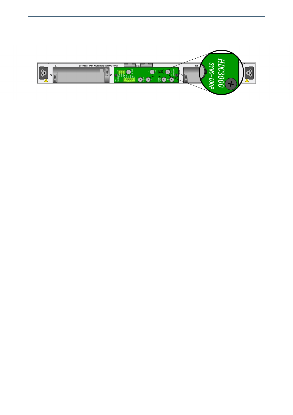
3 - Install the AEM3000P02 rear board ensuring that its 12-pin connectors are properly
aligned with the mounting frame´s mating connectors. Check that the orientation of
the board is correct by looking at the placement of the text printed on it according to
the illustration below.
Details for installation of the module in 3 RU mounting frames
13
Albalá Ingenieros | Manual AEM3000C01
Details for installation of the module in 1 RU mounting frames
4 - Attach the rear board to the mounting frame with two M3 metric screws and tighten.
5 - Verify that the main board is configured according to the user requirements. The
configuration process is detailed later in the INSTALLATION section of this manual.
6 - Insert the AEM3000P01 board (main board of the AEM3000C01 module) into the
front of the mounting frame. The edges of the card slide into two plastic guides inside
the mounting frame.
7 - Affix the main board to the mounting frame using the two screws included on the
front panel.
After these steps, the module is ready to be connected to other equipment.
14

Albalá Ingenieros | Manual AEM3000C01
3.7. Interconnection
The following figure shows the AEM3000C01 module rear board connector layout.
Rear view of the AEM3000C01
The module provides of SDI digital video input (IN) and two outputs (OUT1,OUT2). It also
includes four inputs for analog audio (STREAM 1A,STREAM 1B,STREAM 2A and STREAM
2B). The remaining connectors shown in the silkscreening on the rear board are not used
in this device.
The rear interconnection board is not designed to withstand mechanical stress. The
wiring must be fastened properly to the frame where the mounting frame is housed to
prevent the rear board from supporting the weight of the cables.
3.7.1. Electrical SDI video connections
All electrical SDI video connections are BNC type. The following suggestions should be
kept in mind when wiring the electrical signals.
15

Albalá Ingenieros | Manual AEM3000C01
BNC connectors used on cables must be suitable for the high frequencies of digital
video signals: it is strongly recommended to use high quality connectors from well
known manufacturers.
All coaxial cable used must be Belden 8281 or similar. This type provides the greatest
lengths because it is used to calculate the equalizers in the AEM3000C01. Cables
carrying signal between the module and the devices should use single piece
construction, avoiding spliced sections with double BNC female or barrel connectors.
If it is necessary to split the cable into two sections the same type of wire should be
used in both sections.
The use of analog video coaxial cables RG-59 type or similar is not recommended for
digital video except for very short distances.
3.7.2. Analog audio connections
Analog audio inputs are high impedance, balanced and use 3.81mm pitch terminal
block connectors. If another termination resistance is required, a resistor with the
desired termination value can be externally mounted between the + and - terminals.
For analog audio connections two-wire shielded cable is preferred. The GND terminal
allows connection of the cable shield.
16

Albalá Ingenieros | Manual AEM3000C01
4. OPERATION
This section describes the significance of the front panel indicators of the AEM3000C01
module and their remote control and monitoring ability.
4.1. Front panel description
The appearance of the front panel and the elements it contains are shown in the
following illustration.
Front panel of the AEM3000C01
The panel contains the following elements:
17

Albalá Ingenieros | Manual AEM3000C01
In the CH. FAIL box:
SDI: Red. Error in the serial digital video signal. This LED lights up when no
signal is present, when the signal does not have the correct binary velocity
or when the cable is too long and the signal arrives with too much
attenuation. Reception of a video signal with EDH or checksum errors in
the audio packets will cause this LED to blink at half-second intervals.
AUDIO 1,
AUDIO 2: Red. These LEDs light up continuously when no signal is present at the
analog audio inputs, and they blink if the corresponding channel has an
overload. AUDIO 1 refers to the first two audio channels and AUDIO 2
refers to the last two. Configuration of the thresholds for detection of a
lack of signal and overload are found in the control registers of the
module. The thresholds for lack of signal and overload come from the
factory configured as -50 dBfs and -1 dBfs respectively.
In the lower box:
1/2/3/4: Green. These LEDs light up at low intensity to indicate which audio groups
are present in the SDI signal. Whichever LED is lit the brightest indicates
the embedded audio group that is currently being embedded.
GROUP SEL.: Pushbutton. This button selects the audio group to be embedded.
4.2. Configuration from the front panel
The SDI stream is capable of carrying up to four audio groups, where each group
contains two or four audio signals that are independently encoded at 20 or 24 bits.
Selection of the group to be embedded is done via the front panel pushbutton or can be
done with a computer when a communications controller module is installed in the
same mounting frame as the AEM3000C01.
The pushbutton operates in the following manner:
1.- Press and hold the button for more than one second to select the group.
2.- The green audio group LED that was brightest will begin to blink at approximately
one-half second intervals, indicating that the module is in configuration mode.
3.- Use brief presses of the button to make the LED corresponding to the audio group to
be embedded blink.
4.- Press and hold the button for more than one second to confirm the selection.
5.- The associated LED stops blinking and the group being embedded changes to the
group with the brightest LED.
The other LEDs lit at lower intensity indicate that the SDI video signal has embedded
audio in the group corresponding to each LED.
18

Albalá Ingenieros | Manual AEM3000C01
4.3. The pre-processing block
The AEM3000C01 includes an audio pre-processing block that operates in the digital
domain, prior to the A/D conversion. This block provides level adjustment, phase
inversion and a small selection matrix between the four inputs and four outputs. The
following figure explains the contents of this block along with their default
configuration upon leaving the factory.
AUDIO PRE-PROCESSING BLOCK OF THE AEM3000C01
The 180ophase inversion circuits allow reversal of the polarity of each of the audio
signals.
The level adjust circuit can independently modify the gain of each output signal of the
matrix. The adjustment range is 127 steps of 0.5dB each, going from -39.5dB to +24dB.
The signal can also be muted. The full scale level of the output signal can be set between
15 and 24dBu using program jumpers.
The input matrix can connect any of the four inputs to the channels of the group being
embedded. The matrix is not a blocking type and can connect any one input to more
than one output.
The pre-processing block is only accessible via the communications controller. The
configuration to be performed by this block can be stored in the non-volatile EEPROM of
the module.
19

Albalá Ingenieros | Manual AEM3000C01
HUB/SWITCH
TL3000
COMMUNICATIONS
CONTROLLER MODULE
OTHER TL3000
MODULES
Ethernet
Ethernet
Ethernet
Ethernet
REMOTE CONTROL UNIT
EIA-RS232
EIA-RS485
TLE3100
LINK
FULLDUP.
100M
RXPCK.
TXPCK.
ERROR
ETHERNET
RXCMD.
TXCMD.
ERROR
EIA-232/485
RX DATA
TX DATA
INT.BUS
DEM3000 DEM3000 DEM3000 DEM3000 DEM30 00 DEM3000 DEM3000 DEM3000 DEM300 0 DEM3000 DEM3000 DEM3000 DEM3000
UR3000 INTERNAL BUS
TLE3100
LINK
FULLDUP.
100M
RXPCK.
TXPCK.
ERROR
ETHERNET
RXCMD.
TXCMD.
ERROR
EIA-232/485
RX DATA
TX DATA
INT.BUS
DEM3000 DEM3000 DEM3000 DEM3000 DEM30 00 DEM3000 DEM3000 DEM3000 DEM300 0 DEM3000 DEM3000 DEM3000 DEM3000
UR3000 INTERNAL BUS
Module remote control and supervision
4.4. Module remote control and supervision
The AEM3000C01 can optionally be remotely controlled/supervised.
In order to perform remote configuration and supervision of the module an optional
TL3000 family remote communications controller must be installed in the mounting
frame.
The main function of the communications control module is to interface between a
10/100 Ethernet port, an EIA-RS232 or an EIA-RS485 serial port and the internal bus of
the mounting frame. The following illustration shows the most common control
situations: from a computer or control panel via Ethernet, from a computer via an
EIA-RS232 serial port and from a control panel via an EIA-RS485 serial port.
Certain communications control modules provide additional, more advanced functions
such as an SNMP agent, logging of status changes of the modules and a Web interface
for remote control, etc.
Software for simple configuration and supervision with a GUI for multiple modules can
be downloaded from the Albalá Ingenieros website.
20
Table of contents
Other Albalá Ingenieros, S.A. Control Unit manuals


