Albalá Ingenieros GPD2000C01 User manual

GPD2000C01
1 INPUT TO 4 OUTPUTS GNSS ANTENNA SIGNAL DISTRIBUTION AMPLIFIER
Version 1.0
Albalá Ingenieros, S.A.
Medea, 4 - 28037 Madrid - Spain
13 January 2022 - © Albalá Ingenieros S.A. - All rights reserved

GPD2000C01

GPD2000C01
1 INPUT TO 4 OUTPUTS GNSS ANTENNA SIGNAL DISTRIBUTION AMPLIFIER
Version 1.0
1. DESCRIPTION ...................................................................................................................... 5
1.1. The GPD2000C01 ........................................................................................................................... 5
1.2. Features ............................................................................................................................................. 6
1.3. Block diagram .................................................................................................................................. 7
2. SPECIFICATIONS ................................................................................................................. 9
3. INSTALLATION .................................................................................................................. 11
3.1. Initial inspection .......................................................................................................................... 11
3.2. Safety instructions ...................................................................................................................... 11
3.3. Environmental considerations ................................................................................................ 12
3.4. Installing the module in the mounting frame ................................................................... 12
3.5. Interconnection ............................................................................................................................ 13
4. OPERATION ...................................................................................................................... 15
4.1. Front panel description .............................................................................................................. 15
4.2. Functional description ............................................................................................................... 16
4.3. Module remote control and supervision ............................................................................. 18
4.3.1. Details of the GPD2000C01 registers .......................................................................... 19
5. GLOSSARY ........................................................................................................................ 21
6. REGULATIONS .................................................................................................................. 23
7. VERSIONS ......................................................................................................................... 25

GPD2000C01

Albalá Ingenieros | Manual GPD2000C01
1. DESCRIPTION
1.1. The GPD2000C01
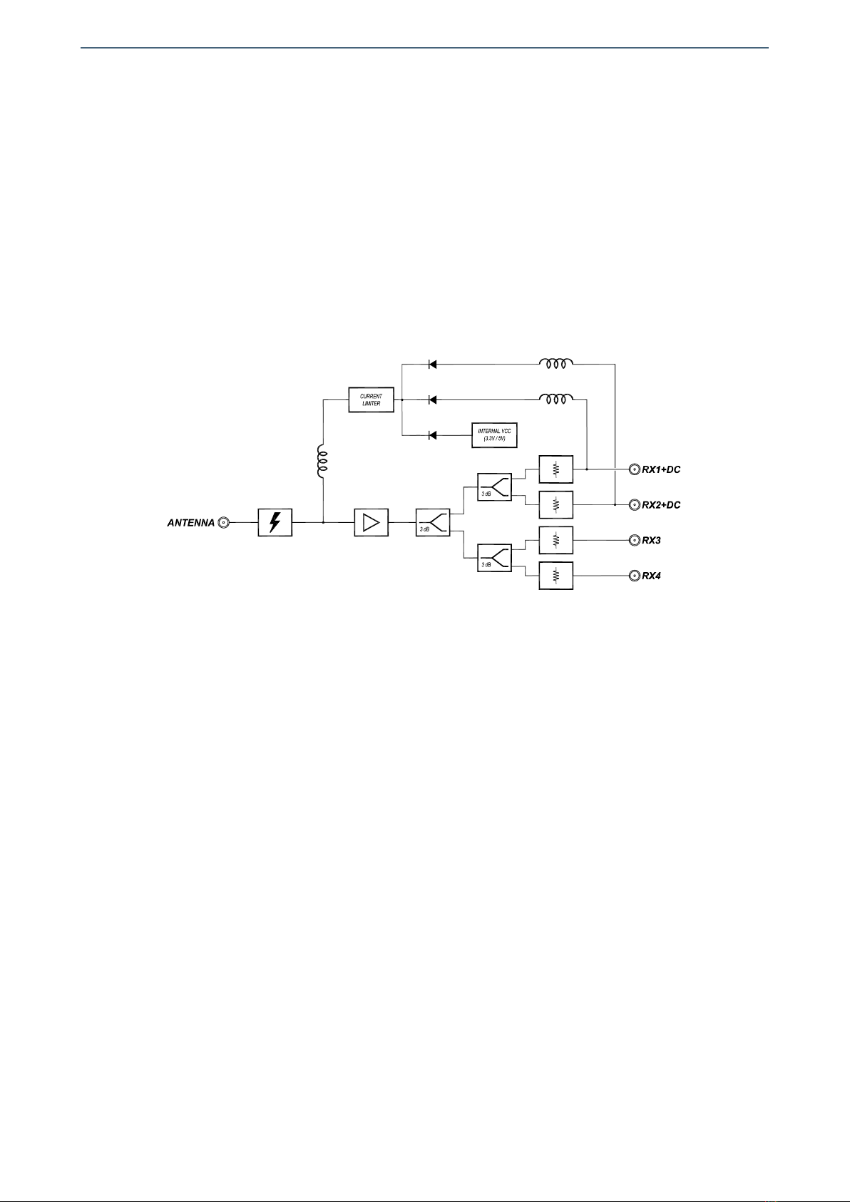
The GPD2000C01 module is a GNSS signal distributor from one input to four outputs
that provides a 20dB gain between the input and any of the outputs in order to
compensate the attenuation introduced by the cable through which the signal is
received from the antenna.
The module has a high enough bandwidth to distribute all of the global navigation
satellite system (GNSS) frequency bands. These systems use the L Band and their
frequencies range from 1.1 to 1.6GHz.
GNSS signals use active antennas and usually require a power supply voltage of 3.3V or
5V to operate. This voltage is provided through the same coaxial cable that is used to
receive the GNSS signal.
The voltage used to power the antenna can come from an internal power supply to the
GPD2000C01 module or from one of the GNSS receivers the GPD2000C01 has connected
to the outputs labeled RX1+DC and RX2+DC. The power supply used at any given
moment is the one with the highest voltage and the three power supplies are redundant
such that as long as one of them is valid the antenna remains powered.
It is possible to monitor the GPD2000C01 status remotely using a communications
controller module installed in the same mounting frame. In addition, certain controller
modules provide SNMP management and the ability to record events in a file including
date and time information for further analysis.
The GPD2000C01 is a TL2000 terminal line module and can be housed in a two rack unit
(2 RU) UR2000 mounting frame.
5

Albalá Ingenieros | Manual GPD2000C01
1.2. Features
• The GPD2000C01 module is a GNSS signal distributor from one input to four outputs.
•Provides a 20dB gain between the input and any of the outputs in order to compensate
the attenuation introduced by the cable through which the signal is received from the
antenna.
•The bandwidth of the module is enough to distribute all the frequency bands of the
global navigation satellite system (GNSS) whose frequencies range between 1.1 and
1.6GHz.
• Includes an internal voltage supply of 3.3V or 5V to power the antenna.
•Provides redundancy for the voltage used to power the antenna by allowing use of the
internal voltage supply of the GPD2000C01 module or either of the voltage supplies
coming from the GNSS receivers the GPD2000C01 has connected to its outputs labeled
RX1+DC and RX2+DC.
•Module control and supervision can be done remotely when the mounting frame is
equipped with a communications controller module.
• Low power.
6
Albalá Ingenieros | Manual GPD2000C01
1.3. Block diagram
7

Albalá Ingenieros | Manual GPD2000C01
GPD2000C01
8

Albalá Ingenieros | Manual GPD2000C01
2. SPECIFICATIONS
Antenna conection for GPS signal
Connector SMA female
Impedance 50 Ω
Standing wave ratio (VWSR) 2:1
Provided antenna voltage 3V or 5V ± 5 %
user selectable
Provided antenna current 80mA max.
Others Antenna input immune to shock waves
< 2 kV as per IEC 61000-4-5
Signal amplifier
Gain 20 dB
Noise factor <4 dB
Dynamic range 0 dBm
3 dB cuttoff frequency:
Lower <1 GHz
Upper >1.6 GHz
Passive splitter
Connector SMA
Impedance 50 Ω
Number of outputs 4
Output return loss >10dB 1GHz to 1,6 GHz
Insertion loss 6 dB
Separation between outputs >12dB 1GHz to 1,6 GHz
General
Power consumption 1 W
Operating temperature range 0 .. 50 °C
Approximate weight 154 g
9

Albalá Ingenieros | Manual GPD2000C01
GPD2000C01
10

Albalá Ingenieros | Manual GPD2000C01
3. INSTALLATION
THE GPD2000C01 MODULE CONTAINS ELECTRONIC DEVICES SENSITIVE TO
ELECTROSTATIC DISCHARGE. Always use antistatic bags clearly identified
with a high degree of shielding for storage and transportation.
3.1. Initial inspection
Verify that the package has been properly handled during transport. After opening the
packaging, check that the GPD2000C01 module is inside.
You must notify your Albalá Ingenieros distributor or dealer of any damage or defects
observed.
Follow the instructions in this manual to install this module in the mounting frame.
3.2. Safety instructions
•This equipment must be connected to a mains outlet with a protective
earth connection. Never use extension cords that do not have protective
earthing connection. The lack of an effective electrical connection between
the ground pin in the mains input connector of the equipment and the
protective earth of the electrical power distribution can cause serious harm.
•All modules of the Albalá Ingenieros TL2000 terminal line can be
hot-plugged or unplugged without suffering any damage or affecting the
processes that are currently taking place in other modules in the same
mounting frame.
•The GPD2000C01 module and the mounting frame should always be
installed, maintained, operated and removed by personnel with sufficient
technical qualifications. The equipment should never be placed in damp
areas, near splashing liquid, or in explosive or corrosive atmospheres.
Neither modules nor mounting frames can be used in applications that
could endanger human life.
11

Albalá Ingenieros | Manual GPD2000C01
3.3. Environmental considerations
This symbol indicates that this equipment must be deposited at a collection
point for proper waste treatment once it has reached the end of its useful
life.
3.4. Installing the module in the mounting frame
The following steps should be followed in order to install a GPD2000C01 module in the
mounting frame.
1 - Remove the blank panel covering the front of the empty slot chosen for installing the
GPD2000C01 in the mounting frame.
2 - Insert the GPD2000C01 module into the front of the mounting frame. The edges of
the card slide into two plastic guides inside the mounting frame.
3 - Secure the module to the mounting frame using the two front screws.
After these steps, the module is ready to be connected to other equipment.
12
Albalá Ingenieros | Manual GPD2000C01
3.5. Interconnection
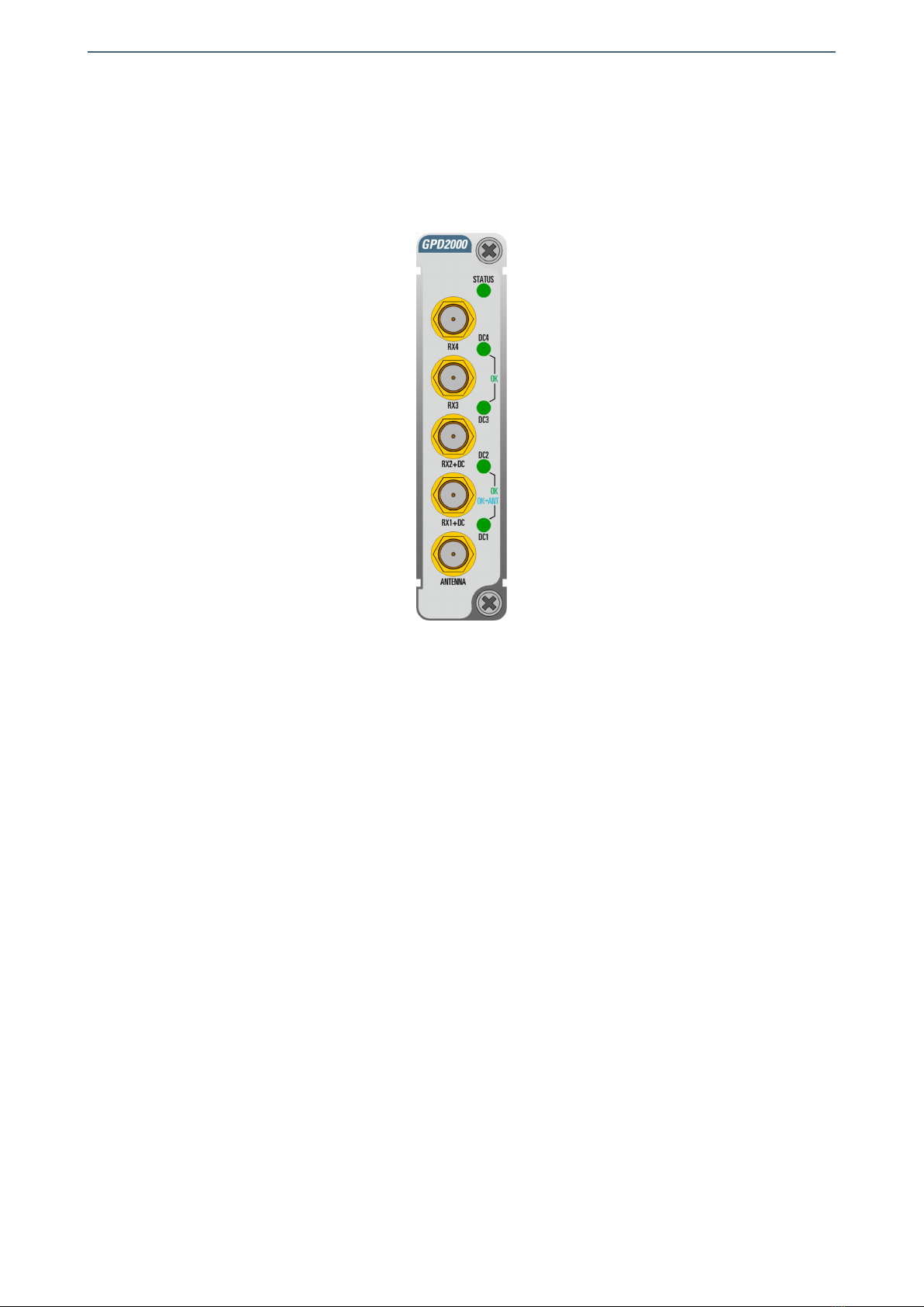
The arrangement of the front panel connectors of the GPD2000C01 module is shown in
the following figure.
Front panel of the GPD2000C01
The SMA connector identified on the front of the module as ANTENNA is the GNSS signal
input and also the voltage supply output. This connector is used to connect the module
to the antenna.
The SMA connectors on the front of the module labelled RX1+DC,RX2+DC,RX3 and RX4
are the outputs of the distributed GNSS signal to be sent to the GNSS receiver modules.
Those receivers connected to outputs with DC are the ones that can be used to provide
redundancy to the antenna power supply.
Connections between the antenna and the GNSS receivers should be made using
low-loss coaxial cable with a 50Ω characteristic impedance.
The GNSS system uses a frequency range from 1.1 to 1.6GHz. Make sure to use cables
and connectors of known quality.
The front panel has not been designed to support mechanical stress. All cabling in the
rack where the mounting frame is located should be properly supported so that the front
panel does not provide mechanical support.
13

Albalá Ingenieros | Manual GPD2000C01
GPD2000C01
14

Albalá Ingenieros | Manual GPD2000C01
4. OPERATION
This section describes the significance of the front panel indicators of the GPD2000C01
module and their remote control and monitoring ability.
4.1. Front panel description
The appearance of the front panel and the elements it contains are shown in the
following illustration.
Front panel of the GPD2000C01
In addition to the connectors previously described in the Interconnection section the
front panel includes the following indicators and controls:
STATUS: This LED lights up in red if the current being delivered via the connector is
below the minimum set threshold, indicating that no antenna is connected. It
blinks in red when the current being delivered through the connector is above
the set threshold, indicating a problem with the antenna or a short circuit. This
LED lights up in yellow if the voltage at one of the connectors is below the
minimum set threshold. In all other cases this LED lights up in green. The
conditions that make this LED light up in yellow or red can be deactivated using
the error masks controls via the control software.
15

Albalá Ingenieros | Manual GPD2000C01
DC4,
DC3: These LED's light up in green when they detect a DC voltage between the RX4
and RX3 connectors. This indicates that these outputs are connected to GNSS
signal receivers that are supplying voltages to power an antenna.
DC2,
DC1: These LED's light up in green when they detect a DC voltage between the RX2
and RX1 connectors. This indicates that these outputs are connected to GNSS
signal receivers that are supplying voltages to power an antenna. When the
voltage supplied by either of these two connectors is the one being used to
power the antenna then that output's LED lights up in cyan.
4.2. Functional description
The GPD2000C01 distributes the GNSS signal received from an antenna to four outputs.
It also includes and amplifier that provides a 20dB gain between the input and any of
the outputs to compensate for the attenuation introduced by the cable that connects
the module to the antenna.
The module has a high enough bandwidth to distribute all of the global navigation
satellite system (GNSS) frequency bands. These systems use the L Band and their
frequencies range from 1.1 to 1.6GHz.
GNSS signals use antennas that are active and they require a power supply voltage of
3.3V or 5V to operate. This voltage is provided through the same coaxial cable that
receives the GNSS signal. The voltage used to power the antenna can come from an
internal power supply to the GPD2000C01 module or from one of the GNSS receivers the
GPD2000C01 has connected to the outputs labeled RX1+DC and RX2+DC. The power
supply used at any given moment is the one with the highest voltage and the three
power supplies are redundant such that as long as one of them is valid the antenna
remains powered.
The GPD2000C01 allows supervision of the DC voltage it receives from the GNSS
receivers over each connector via which it distributes signal and is also capable of
measuring the voltage supplied to the antenna and its current consumption.
The thresholds for minimum and maximum current that the antenna can consume as
well as the minimum voltage that should be available at the connectors can be set with
the control software. These thresholds activate error indicators that can be logged locally
and queried remotely via a communication module installed in the same mounting
frame.
The error indicators are also used to determine the color when the front panel STATUS
LED lights up. Each error indicator provides a control that can prevent the STATUS LED
from indicating the status of the error. For example, if one of the outputs is not being
used or of the GNSS receiver to which the output is connected is not providing voltage to
power the antenna then the error mask can be deactivated such that the LED lights up in
green instead of yellow.
16

Albalá Ingenieros | Manual GPD2000C01
17

Albalá Ingenieros | Manual GPD2000C01
HUB/SWITCH
TL2000
COMMUNICATIONS
CONTROLLER MODULE
OTHER TL2000
MODULES
Ethernet
Ethernet
Ethernet
Ethernet
REMOTE CONTROL UNIT
TLE2001 PSU2000 PSU2000
TLE2001 PSU2000 PSU2000
UR2000 INTERNAL BUS
UR2000 INTERNAL BUS
Module remote control and supervision
4.3. Module remote control and supervision
The GPD2000C01 can optionally be remotely controlled/supervised.
In order to perform remote configuration and supervision of the module an optional
TL2000 family remote communications controller must be installed in the mounting
frame.
The main function of the communications control module is to interface between a
10/100 Ethernet port and the internal bus of the mounting frame. The following
illustration shows the most common control situations: from a computer or control
panel via Ethernet.
Certain communications control modules provide additional, more advanced functions
such as an SNMP agent, logging of status changes of the modules and a Web interface
for remote control, etc.
Software for simple configuration and supervision with a GUI for multiple modules can
be downloaded from the Albalá Ingenieros website.
18

Albalá Ingenieros | Manual GPD2000C01
The following functions of the GPD2000C01 can be performed remotely:
- Adjustment of the thresholds for minimum and maximum current by the antenna.
-Adjustment of the threshold for minimum power supply voltage that should be
available at the connectors.
-Activation of the internal power supply of the module and the voltage it provides to
the antenna.
- Configuration of the error masks that control the behavior of the STATUS LED.
-Supervision of the voltage and current supplied to the antenna and the voltage
provided by the GNSS receivers to which the signal is distributed.
4.3.1. Details of the GPD2000C01 registers
The GPD2000C01 module provides control and status registers that can be read and
written by means of specific commands described in the communication control
module user manuals.
The parameter information grouped in the CONTROL or RAM sections is stored in
volatile memory. Any modifications to the parameters will be lost when the module
power supply is disconnected unless the "EEPROM Save" button within the software
has been pressed.
The STATUS section parameters are read-only and cannot be modified.
The EEPROM section parameters are rarely used and are stored directly in non-volatile
memory.
The parameters that can be controlled and supervised remotely for each version of
the firmware are listed below:
VERSION 1.X
CONTROL
Name add ext msk snmp trap Description
GPD_VCC_DISABLE 0x00 0x01 N N Disable internal VCC
0=Disabled, 1=Enabled
GPD_VCC_5V_3V3_N 0x00 0x02 N N Internal VCC level
0=3.3 V, 1=5 V
VCC_GNSS1_F_MASK 0x01 0x01 N N VCC GNSS Input 1 fail mask
0=Disabled, 1=Enabled
VCC_GNSS2_F_MASK 0x01 0x02 N N VCC GNSS Input 2 fail mask
0=Disabled, 1=Enabled
VCC_GNSS3_F_MASK 0x01 0x04 N N VCC GNSS Input 3 fail mask
0=Disabled, 1=Enabled
VCC_GNSS4_F_MASK 0x01 0x08 N N VCC GNSS Input 4 fail mask
0=Disabled, 1=Enabled
VCC_ANT_F_MASK 0x01 0x10 N N VCC antenna fail mask
0=Disabled, 1=Enabled
ICC_ANT_F_MASK 0x01 0x20 N N ICC antenna fail mask
0=Disabled, 1=Enabled
NO_ANTENNA_MASK 0x01 0x80 N N Antenna presence fail mask
0=Disabled, 1=Enabled
19

Albalá Ingenieros | Manual GPD2000C01
VCC_GNSS_LOW 0x02 0xFF Y N VCC low threshold
= x/45 V
ICC_ANTENNA_LOW 0x03 0xFF Y N ICC low threshold
= x/3.4 mA
ICC_ANTENNA_HIGH 0x04 0xFF Y N ICC high threshold
= x/3.4 mA
STATUS
Name add ext msk snmp trap Description
VCC_GNSS1_FAIL 0x01 0x01 Y Y VCC GNSS Input 1 fail
0=OK,1=Fail
VCC_GNSS2_FAIL 0x01 0x02 Y Y VCC GNSS Input 2 fail
0=OK,1=Fail
VCC_GNSS3_FAIL 0x01 0x04 Y Y VCC GNSS Input 3 fail
0=OK,1=Fail
VCC_GNSS4_FAIL 0x01 0x08 Y Y VCC GNSS Input 4 fail
0=OK,1=Fail
VCC_ANTENNA_FAIL 0x01 0x10 Y Y VCC antenna fail
0=OK,1=Fail
ICC_ANTENNA_FAIL 0x01 0x20 Y Y ICC antenna fail
0=OK,1=Fail
NO_ANTENNA 0x01 0x80 Y Y Antenna presence fail
0=OK,1=Fail
DC_GNSS1 0x02 0xFF Y N VCC GNSS Input 1
= x/45 V
DC_GNSS2 0x03 0xFF Y N VCC GNSS Input 2
= x/45 V
DC_GNSS3 0x04 0xFF Y N VCC GNSS Input 3
= x/45 V
DC_GNSS4 0x05 0xFF Y N VCC GNSS Input 4
= x/45 V
ANTENNA_VCC 0x06 0xFF Y N Antenna supply VCC
= x/45 V
ANTENNA_ICC 0x07 0xFF Y N Antenna supply ICC
= x/3.4 mA
20
Table of contents
Other Albalá Ingenieros Amplifier manuals


