Albalá Ingenieros DVM3001C02 User manual

DVM3001C02
DUAL 1 INPUT TO 4 OUTPUTS SD-SDI DIGITAL VIDEO DISTRIBUTOR WITH 2
CCVS ANALOG COMPOSITE VIDEO OUTPUTS AND ONE SD-SDI SAFE
OUTPUT PROTECTED WITH BYPASS RELAYS IN THE REAR BOARD
Version 1.0
Albalá Ingenieros, S.A.
Medea, 4 - 28037 Madrid - Spain
27 February 2017 - © Albalá Ingenieros S.A. - All rights reserved

DVM3001C02

DVM3001C02
DUAL 1 INPUT TO 4 OUTPUTS SD-SDI DIGITAL VIDEO DISTRIBUTOR WITH 2
CCVS ANALOG COMPOSITE VIDEO OUTPUTS AND ONE SD-SDI SAFE OUTPUT
PROTECTED WITH BYPASS RELAYS IN THE REAR BOARD
Version 1.0
1. DESCRIPTION ...................................................................................................................... 5
1.1. The DVM3001C02 .......................................................................................................................... 5
1.2. Features ............................................................................................................................................. 6
1.3. Block diagram .................................................................................................................................. 7
2. SPECIFICATIONS ................................................................................................................. 9
3. INSTALLATION .................................................................................................................. 11
3.1. Initial inspection .......................................................................................................................... 11
3.2. Safety instructions ...................................................................................................................... 11
3.3. Environmental considerations ................................................................................................ 12
3.4. Power considerations ................................................................................................................. 12
3.5. Module configuration ................................................................................................................ 12
3.6. Installing the module in the mounting frame ................................................................... 12
3.7. Interconnection ............................................................................................................................ 14
3.7.1. Electrical SDI video connections .................................................................................... 15
3.7.2. Analog video connections ................................................................................................ 15
4. OPERATION ...................................................................................................................... 17
4.1. Front panel description .............................................................................................................. 17
4.2. Module remote control and supervision ............................................................................. 19
4.2.1. Details of the DVM3001C02 registers ......................................................................... 20
5. GLOSSARY ........................................................................................................................ 23
6. REGULATIONS .................................................................................................................. 25
7. VERSIONS ......................................................................................................................... 27

DVM3001C02

Albalá Ingenieros | Manual DVM3001C02
1. DESCRIPTION
1.1. The DVM3001C02
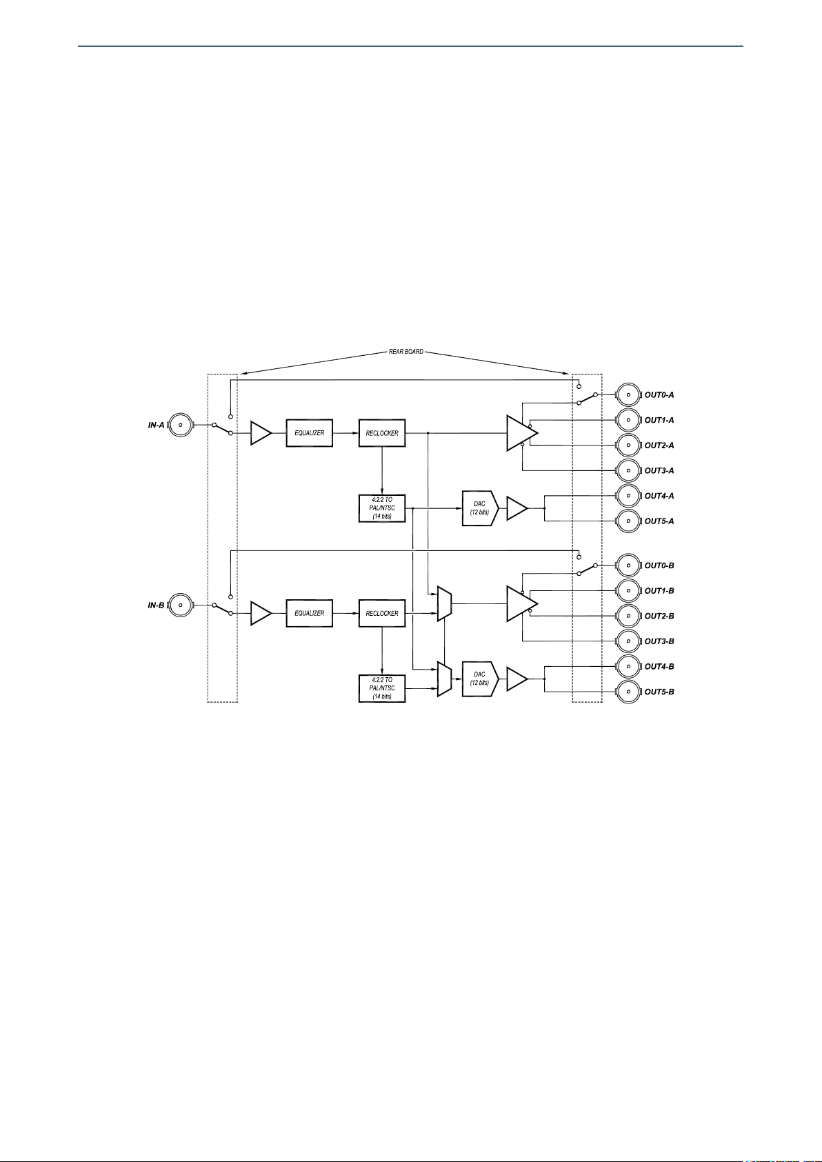
The DVM3001C02 module is a 270Mbit/s SDI video distributor featuring conversion to
analog composite video with 12 bits of resolution. It consists of two sections, each
containing a distributor for digital video with four outputs that provide equalization and
reclocking along with a 4:2:2 PAL/NTSC encoder with two outputs. The DVM3001C02
can also be configured as a single distributor with eight outputs that provide
equalization and reclocking along with a 4:2:2 PAL/NTSC encoder with four outputs.
The DVM3001C02 has been designed for applications where in addition to distribution
of digital video signals a high quality analog video signal is also needed.
Each section of the DVM3001C02 includes a bypass relay on the rear board that
connects the input signal to one of the SD-SDI outputs in case of a power supply failure
or if the main board of the module is removed.
It is possible to monitor the DVM3001C02 status remotely using a communications
controller module installed in the same mounting frame. In addition, certain controller
modules provide SNMP management and the ability to record events in a file including
date and time information for further analysis.
The DVM3001C02 is a TL3000 terminal line module and can be housed in a three rack
unit (3 RU) UR3000 mounting frame or a 1 RU UR3100 mounting frame.
The DVM3001 family includes several SD-SDI digital video distributors and CCVS
composite video converters, with the following variations:
•DVM3001C01: Dual SD-SDI digital video distributor with one input to four outputs and
two CCVS analog composite video outputs.
•DVM3001C02: Dual SD-SDI digital video distributor with one input to four outputs, two
CCVS analog composite video outputs and one SD-SDI output protected with a bypass
relay on the rear board.
5

Albalá Ingenieros | Manual DVM3001C02
1.2. Features
• Dual SD-SDI digital video distributor with composite video encoder.
• Provides two sections, each equipped with:
- A one input to four output SD-SDI video distributor.
- A PAL/NTSC composite video encoder with two outputs.
•Can be configured to distribute one input to eight outputs with four PAL/NTSC video
outputs.
•Each section provides a bypass relay on the rear board that enables the input signal to
be passed through to one of the SD-SDI outputs in case of power loss or module
removal.
•Provides automatic equalizers at the inputs capable of compensating 300+ meters of
Belden 8281 cable.
• Includes reclocking.
• Automatic detection of input signal format (525/625 lines).
• Front panel indicators for signal presence and maximum equalization.
• Provides presets for module configuration storage.
•Module control and supervision can be done remotely when the mounting frame is
equipped with a communications controller module.
•One UR3000 mounting frame can house up to 12 DVM3001C02 modules. If power
supply redundancy is required and FA3000 or FA3001 modules are used then only 10
modules can be housed in the mounting frame. If PSU3300 or PSU3301 modules are
used for this purpose then up to 12 modules can be installed.
• One UR3100 mounting frame can house up to three DVM3001C02 modules.
• Low power.
6
Albalá Ingenieros | Manual DVM3001C02
1.3. Block diagram
7

Albalá Ingenieros | Manual DVM3001C02
DVM3001C02
8

Albalá Ingenieros | Manual DVM3001C02
2. SPECIFICATIONS
SD-SDI digital video signal input
Connector BNC
Impedance 75Ω ± 1 %
Return loss >15dB up to 270 MHz
Input return loss when bypass is active >15dB up to 270 MHz
Output protected with bypass relay Yes
Number of inputs 1 per section, 2 sections
Equalizable cable length:
Belden 8281 >200 m
SD-SDI digital video signal output
Connector BNC
Impedance 75Ω ± 1 %
Return loss >15dB up to 270 MHz
Output return loss when bypass is active >15dB up to 270 MHz
Input to output bypass insertion loss <0.1dB up to 270 MHz
Number of outputs 4 per section
Amplitude 800mVpp ± 10 %
Rise and fall time (20 % - 80 %) 950 ps typ.
SD-SDI digital video signal
Signal format According to SMPTE ST 259 standard
Bit rate 270Mbit/s
Input to output delay 8 ns ± 2 ns
Analog video signal output
Connector BNC
Impedance 75Ω ± 1 %
Return loss >40dB at fsc
Signal format According to ITU-R BT.470-6 standard,
PAL B/G y NTSC M
Number of outputs 2 per section
Separation between outputs >40dB at fsc
DC voltage <50 mV
Analog video signal
Differential gain 0.2 %
Differential phase 0.1 °
Chrominance to luminance delay <5 ns
Video digital to analog converter
Sampling rate 27 MHz
9

Albalá Ingenieros | Manual DVM3001C02
Number of bits 12
General
Maximum power supply current + 440 / - 560 mA
Operating temperature range 0 .. 50 °C
Approximate weight 350 g
10

Albalá Ingenieros | Manual DVM3001C02
3. INSTALLATION
THE DVM3001C02 MODULE CONTAINS ELECTRONIC DEVICES SENSITIVE TO
ELECTROSTATIC DISCHARGE. Always use antistatic bags clearly identified
with a high degree of shielding for storage and transportation.
The DVM3001C02 module is composed of two parts: one DVM3001P01 main board and
one XVD3000P05 rear board. Both parts must be installed in a UR3000 or UR3100
mounting frame following the instructions in the corresponding section of this chapter.
3.1. Initial inspection
Verify that the package has been properly handled during transport. After opening the
packaging, check that one DVM3001P01 main board and one XVD3000P05 rear board
are inside.
You must notify your Albalá Ingenieros distributor or dealer of any damage or defects
observed.
Follow the instructions in this manual to install this module in the mounting frame.
3.2. Safety instructions
•This equipment must be connected to a mains outlet with a protective
earth connection. Never use extension cords that do not have protective
earthing connection. The lack of an effective electrical connection between
the ground pin in the mains input connector of the equipment and the
protective earth of the electrical power distribution can cause serious harm.
•All modules of the Albalá Ingenieros TL3000 terminal line can be
hot-plugged or unplugged without suffering any damage or affecting the
processes that are currently taking place in other modules in the same
mounting frame. When a module is installed in an empty bay of a mounting
frame, it is necessary to mount the rear board that is part of that module.
Prior to installing this board, the mounting frame must be disconnected
from the power supply network. This is required because in addition to the
risk of electrocution for the person handling the device it is possible that a
high instantaneous current coming from the power supply could damage
the connectors and components of the mounting frame and/or the rear
board.
11

Albalá Ingenieros | Manual DVM3001C02
•The DVM3001C02 module and the mounting frame should always be
installed, maintained, operated and removed by personnel with sufficient
technical qualifications. The equipment should never be placed in damp
areas, near splashing liquid, or in explosive or corrosive atmospheres.
Neither modules nor mounting frames can be used in applications that
could endanger human life.
3.3. Environmental considerations
This symbol indicates that this equipment must be deposited at a collection
point for proper waste treatment once it has reached the end of its useful
life.
3.4. Power considerations
The UR3000 and UR3100 mounting frames can house as many DVM3001C02 modules
as will fit in them.
3.5. Module configuration
The DVM3001C02 module includes a set of microswitches for configuration of various
parameters of the digital-to-analog conversion for the PAL/NTSC encoder. These
microswitches are found in device S1.
-Microswitch 1 allows selection of whether or not the non-visible information
received during the vertical intervals of the digital signal of Section A (test signals,
teletext, etc.) is converted to analog format (VBI PASS YES) or eliminated and these
lines converted to black (VBI PASS NO).
-Microswitch 2 allows selection between two different filters for the luminance of
Section A's PAL/NTSC encoder. The normal filter, (LP FILTER NORM) has a flat response
up to the cutoff frequency, whereas the notch filter (LP FILTER NOTCH) eliminates a
band of frequency centered around the sub-carrier frequency. The luminance
channel bandwidth is 6MHz for both 525 and 625 lines.
- Microswitch 3 has the same functionality as Microswitch 1, but for Section B.
- Microswitch 4 has the same functionality as Microswitch 2, but for Section B.
When the DVM3001C02 is configured as a single distributor with one input, eight digital
outputs and four analog outputs then the input for Section A is distributed to all the
outputs and converted to analog composite video. Also, the configuration of Section A
determines the response of all of the outputs.
12
Albalá Ingenieros | Manual DVM3001C02
3.6. Installing the module in the mounting frame
The steps needed to install the DVM3001C02 module with the rear board in the
mounting frame are:
1 - Disconnect all power cords from the power supplies of the mounting frame.
2 - Remove the blank panels covering the front and rear of the empty bays chosen for
installing the DVM3001C02 in the mounting frame.
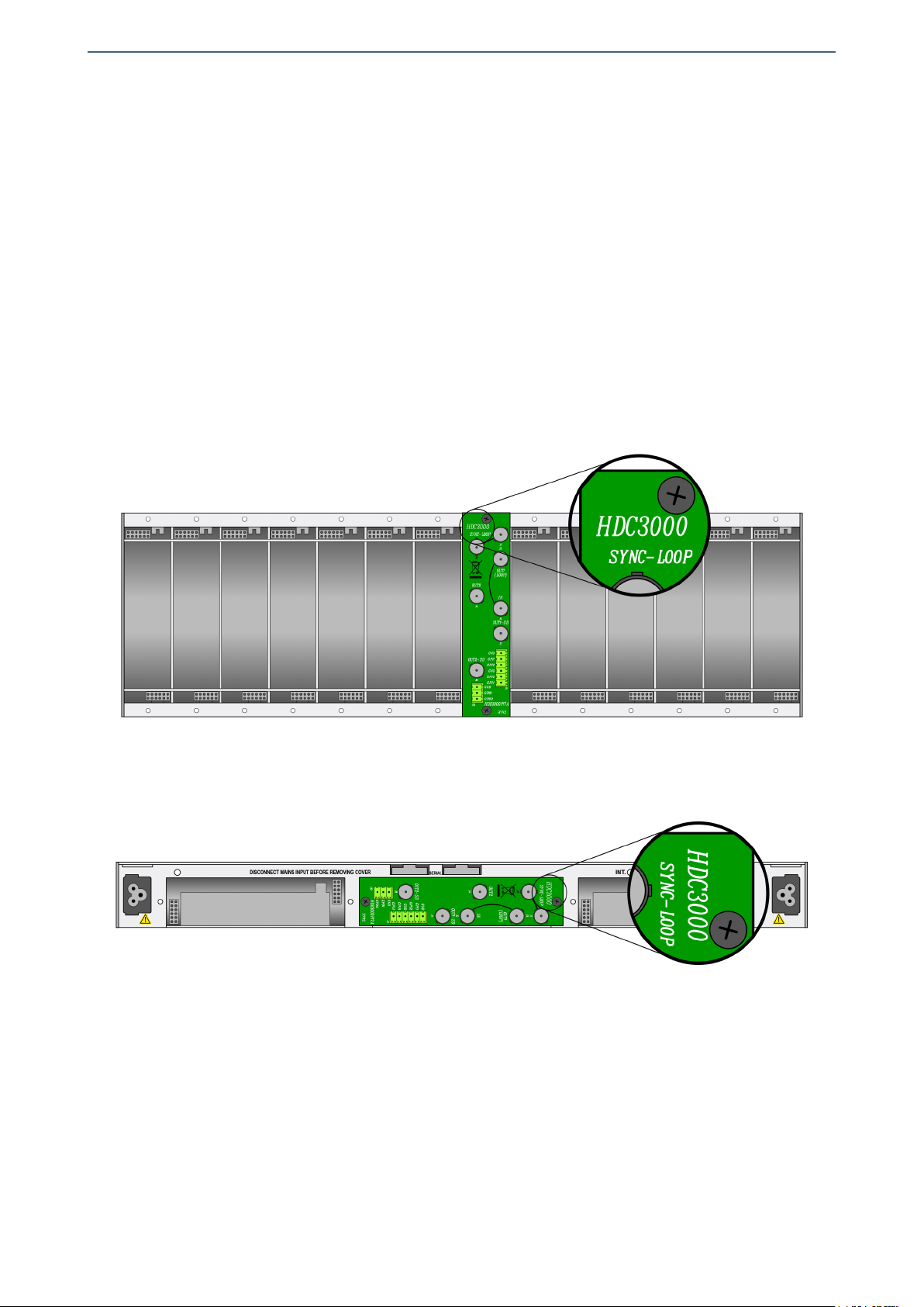
3 - Install the XVD3000P05 rear board ensuring that its 12-pin connectors are properly
aligned with the mounting frame´s mating connectors. Check that the orientation of
the board is correct by looking at the placement of the text printed on it according to
the illustration below.
Details for installation of the module in 3 RU mounting frames
Details for installation of the module in 1 RU mounting frames
4 - Attach the rear board to the mounting frame with two M3 metric screws and tighten.
5 - Verify that the main board is configured according to the user requirements. The
configuration process is detailed later in the INSTALLATION section of this manual.
6 - Insert the DVM3001P01 board (main board of the DVM3001C02 module) into the
front of the mounting frame. The edges of the card slide into two plastic guides inside
13
Albalá Ingenieros | Manual DVM3001C02
the mounting frame.
7 - Affix the main board to the mounting frame using the two screws included on the
front panel.
After these steps, the module is ready to be connected to other equipment.
3.7. Interconnection
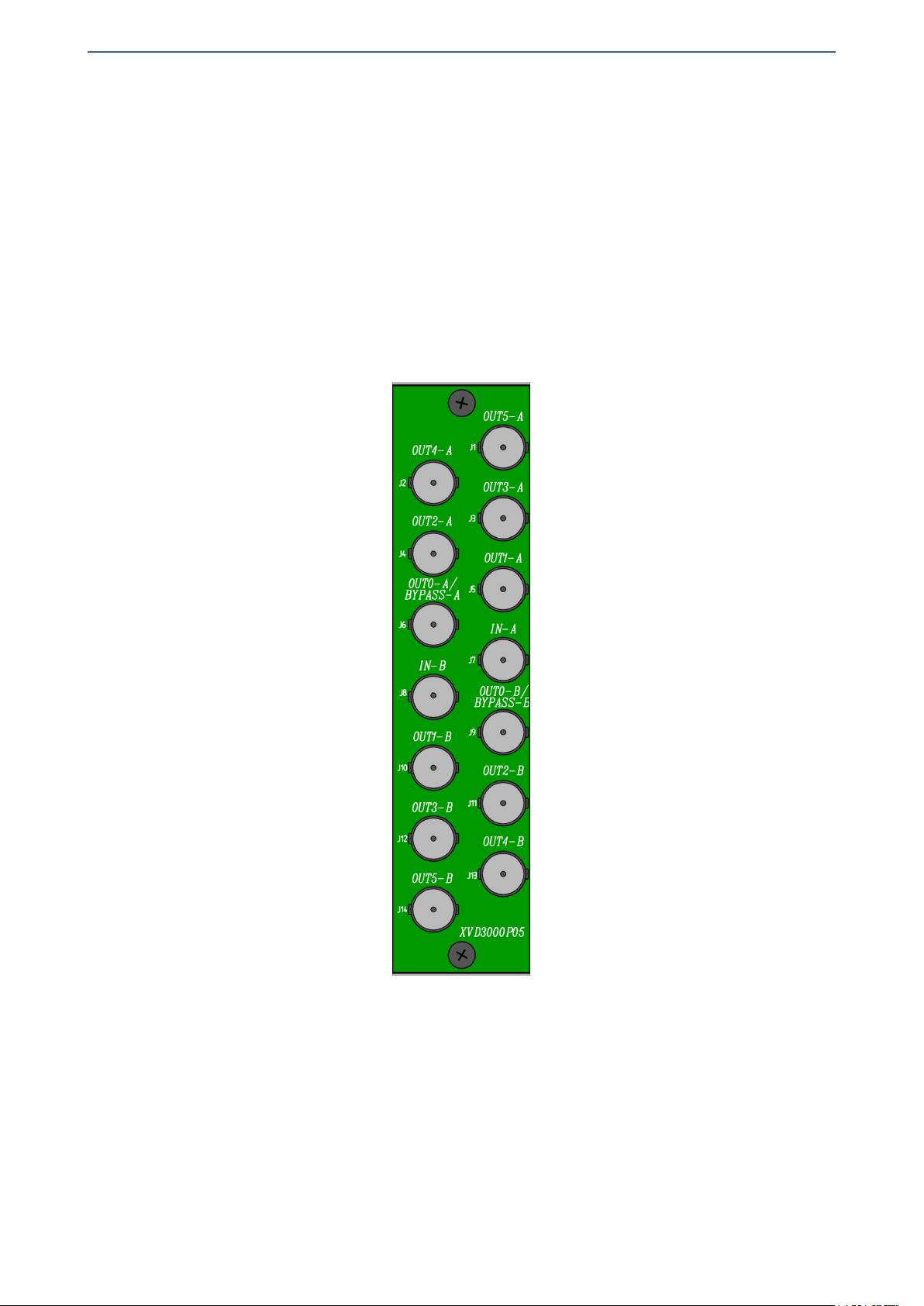
The following figure shows the DVM3001C02 module rear board connector layout.
Rear view of the DVM3001C02
The DVM3001C02 module provides two inputs (IN-A,IN-B), four digital video outputs
(OUT0-A to OUT3-A,OUT0-B to OUT3-B) and two analog composite video outputs
(OUT4-A,OUT5-A,OUT4-B,OUT5-B) for each of its two sections. The connectors labeled
OUT0-A/BYPASS-A or OUT0-B/BYPASS-B corresponds to the outputs whose signals are
protected with bypass relays such that if the power supply fails or the module is
extracted signal continuity from the input is maintained.
14

Albalá Ingenieros | Manual DVM3001C02
The rear interconnection board is not designed to withstand mechanical stress. The
wiring must be fastened properly to the frame where the mounting frame is housed to
prevent the rear board from supporting the weight of the cables.
3.7.1. Electrical SDI video connections
All electrical SDI video connections are BNC type. The following suggestions should be
kept in mind when wiring the electrical signals.
BNC connectors used on cables must be suitable for the high frequencies of digital
video signals: it is strongly recommended to use high quality connectors from well
known manufacturers.
All coaxial cable used must be Belden 8281 or similar. This type provides the greatest
lengths because it is used to calculate the equalizers in the DVM3001C02. Cables
carrying signal between the module and the devices should use single piece
construction, avoiding spliced sections with double BNC female or barrel connectors.
If it is necessary to split the cable into two sections the same type of wire should be
used in both sections.
The use of analog video coaxial cables RG-59 type or similar is not recommended for
digital video except for very short distances.
3.7.2. Analog video connections
The analog video outputs use BNC connectors and have an impedance of 75Ω.
For analog video connections a coaxial cable with 75Ω of characteristic impedance
must be used.
15

Albalá Ingenieros | Manual DVM3001C02
DVM3001C02
16

Albalá Ingenieros | Manual DVM3001C02
4. OPERATION
This section describes the significance of the front panel indicators of the DVM3001C02
module and their remote control and monitoring ability.
4.1. Front panel description
The appearance of the front panel and the elements it contains are shown in the
following illustration.
Front panel of the DVM3001C02
The panel contains the following elements:
17

Albalá Ingenieros | Manual DVM3001C02
In the CHANNEL A and CHANNEL B boxes:
NO SIGNAL: Red. This LED lights up when no signal is present or the signal's format is
incorrect.
Blinks when EDH errors are detected.
MAX. EQ.: Red. This LED lights up when the length of the cable being equalized is
close to the maximum allowed by the DVM3001C02.
18

Albalá Ingenieros | Manual DVM3001C02
HUB/SWITCH
TL3000
COMMUNICATIONS
CONTROLLER MODULE
OTHER TL3000
MODULES
Ethernet
Ethernet
Ethernet
Ethernet
REMOTE CONTROL UNIT
EIA-RS232
EIA-RS485
TLE3100
LINK
FULLDUP.
100M
RXPCK.
TXPCK.
ERROR
ETHERNET
RXCMD.
TXCMD.
ERROR
EIA-232/485
RX DATA
TX DATA
INT.BUS
DEM3000 DEM3000 DEM3000 DEM3000 DEM30 00 DEM3000 DEM3000 DEM3000 DEM300 0 DEM3000 DEM3000 DEM3000 DEM3000
UR3000 INTERNAL BUS
TLE3100
LINK
FULLDUP.
100M
RXPCK.
TXPCK.
ERROR
ETHERNET
RXCMD.
TXCMD.
ERROR
EIA-232/485
RX DATA
TX DATA
INT.BUS
DEM3000 DEM3000 DEM3000 DEM3000 DEM30 00 DEM3000 DEM3000 DEM3000 DEM300 0 DEM3000 DEM3000 DEM3000 DEM3000
UR3000 INTERNAL BUS
Module remote control and supervision
4.2. Module remote control and supervision
The DVM3001C02 can optionally be remotely controlled/supervised.
In order to perform remote configuration and supervision of the module an optional
TL3000 family remote communications controller must be installed in the mounting
frame.
The main function of the communications control module is to interface between a
10/100 Ethernet port, an EIA-RS232 or an EIA-RS485 serial port and the internal bus of
the mounting frame. The following illustration shows the most common control
situations: from a computer or control panel via Ethernet, from a computer via an
EIA-RS232 serial port and from a control panel via an EIA-RS485 serial port.
Certain communications control modules provide additional, more advanced functions
such as an SNMP agent, logging of status changes of the modules and a Web interface
for remote control, etc.
Software for simple configuration and supervision with a GUI for multiple modules can
be downloaded from the Albalá Ingenieros website.
19

Albalá Ingenieros | Manual DVM3001C02
The following functions of the DVM3001C02 can be performed remotely:
-Configuration of the conversion to composite video (vertical interval blanking, filter
type, removal of chrominance).
- Configuration of the module in single or dual mode.
- Supervision of the presence and status of the input signals.
4.2.1. Details of the DVM3001C02 registers
The DVM3001C02 module provides control and status registers that can be read and
written by means of specific commands described in the communication control
module user manuals.
The parameter information grouped in the CONTROL or RAM sections is stored in
volatile memory. Any modifications to the parameters will be lost when the module
power supply is disconnected unless the "EEPROM Save" button within the software
has been pressed.
The STATUS section parameters are read-only and cannot be modified.
The parameters that can be controlled and supervised remotely for each version of
the firmware are listed below:
VERSION 1.X
CONTROL
Name add ext msk snmp trap Description
VBI_PASS_A 0x00 0x01 Y N Allows selecting if the VBI is blanked (Section A)
0=Blank, 1=Pass
VBI_PASS_B 0x00 0x02 Y N Allows selecting if the VBI is blanked (Section B)
0=Blank, 1=Pass
CHROMA_A 0x00 0x04 Y N Allows disabling chroma (Section A)
0=Off, 1=On
CHROMA_B 0x00 0x08 Y N Allows disabling chroma (Section B)
0=Off, 1=On
LUMA_FILTER_A 0x00 0x10 Y N Allows selecting luminance filter (Section A)
0=Notch, 1=Flat
LUMA_FILTER_B 0x00 0x20 Y N Allows selecting luminance filter (Section B)
0=Notch, 1=Flat
CUSTOM_FILTER_A 0x00 0x40 Y N Allows selecting a custom luminance filter (Section A)
0=Custom, 1=Standard
CUSTOM_FILTER_B 0x00 0x80 Y N Allows selecting a custom luminance filter (Section B)
0=Custom, 1=Standard
MODE 0x01 0x04 Y N Allows selecting module operating mode
0=Single, 1=Dual
NO_SIG_A_MASK 0x02 0x01 N N Allows masking no signal fail (Section A)
0=Disabled, 1=Enabled
NO_SIG_B_MASK 0x02 0x02 N N Allows masking no signal fail (Section B)
0=Disabled, 1=Enabled
MAX_EQ_A_MASK 0x02 0x04 N N Allows masking maximum equalization fail (Section A)
0=Disabled, 1=Enabled
MAX_EQ_B_MASK 0x02 0x08 N N Allows masking maximum equalization fail (Section B)
0=Disabled, 1=Enabled
UNLOCK_A_MASK 0x02 0x10 N N Allows masking unlock fail (Section A)
0=Disabled, 1=Enabled
UNLOCK_B_MASK 0x02 0x20 N N Allows masking unlock fail (Section B)
0=Disabled, 1=Enabled
20
Table of contents
Other Albalá Ingenieros Amplifier manuals


