Albalá Ingenieros GTI2000C01 User manual

GTI2000C01
2,048 kHz SYNCHRONIZATION SIGNAL GENERATOR AS PER G.703 T12
Version 1.0
Albalá Ingenieros, S.A.
Medea, 4 - 28037 Madrid - Spain
26 January 2018 - © Albalá Ingenieros S.A. - All rights reserved

GTI2000C01

GTI2000C01
2,048 kHz SYNCHRONIZATION SIGNAL GENERATOR AS PER G.703 T12
Version 1.0
1. DESCRIPTION ...................................................................................................................... 5
1.1. The GTI2000C01 ............................................................................................................................. 5
1.2. Features ............................................................................................................................................. 6
1.3. Block diagram .................................................................................................................................. 7
2. SPECIFICATIONS ................................................................................................................. 9
3. INSTALLATION .................................................................................................................. 11
3.1. Initial inspection .......................................................................................................................... 11
3.2. Safety instructions ...................................................................................................................... 11
3.3. Environmental considerations ................................................................................................ 12
3.4. Installing the module in the mounting frame ................................................................... 12
3.5. Interconnection ............................................................................................................................ 13
4. OPERATION ...................................................................................................................... 15
4.1. Front panel description .............................................................................................................. 15
4.2. Functional description ............................................................................................................... 16
4.3. Module remote control and supervision ............................................................................. 18
4.3.1. Details of the GTI2000C01 registers ............................................................................ 19
5. GLOSSARY ........................................................................................................................ 21
6. REGULATIONS .................................................................................................................. 23
7. VERSIONS ......................................................................................................................... 25

GTI2000C01

Albalá Ingenieros | Manual GTI2000C01
1. DESCRIPTION
1.1. The GTI2000C01
The GTI2000C01 is a 2048kHz synchronization signal generator as per ITU-T G.703 T12.
In order to operate, the module has a 2048kHz oscillator that can synchronize to a
reference provided to it. The output of this oscillator is delivered to four amplifiers with
adaptable output levels, and their outputs are distributed to four connectors located on
the front panel of the device.
When used as a generator, the reference that the oscillator locks to is a 10MHz signal
that it receives from the internal bus of a UR2000 mounting frame. In order to provide
this reference, a GNSS receiver module must also be installed in the mounting chassis
where the GTI2000C01 is located.
When used as a distributor, the oscillator locks to a 2048kHz synchronization signal that
it receives via a connector on the front panel of the device.
If both references are available - 10MHz from the mounting frame bus and the
2048kHz synchronization signal - then the GTI2000C01 can manage redundancy
between these two signals according to a set of priority criteria.
It is possible to monitor the GTI2000C01 status remotely using a communications
controller module installed in the same mounting frame. In addition, certain controller
modules provide SNMP management and the ability to record events in a file including
date and time information for further analysis.
The GTI2000C01 is a TL2000 terminal line module and can be housed in a two rack unit
(2 RU) UR2000 mounting frame.
5

Albalá Ingenieros | Manual GTI2000C01
1.2. Features
•The GTI2000C01 module is a 2048kHz synchronization signal generator as per ITU-T
G.703 T12 that operates by locking to the internal 10MHz reference of a UR2000
mounting frame.
•In order to provide the internal 10MHz reference, the mounting chassis where the
GTI2000C01 is located must have a GPS2000C01 GNSS receiver module installed to
generate it.
•The module also includes an input on the front panel for 2048kHz synchronization
signals. This input can be used to turn the GTI2000C01 into a distributor or into an
automated switch between the internal 10MHz reference signal and the signal
received via the front panel.
• The module provides four 2048kHz synchronization signal outputs.
•Module control and supervision can be done remotely when the mounting frame is
equipped with a communications controller module.
• Low power.
6

Albalá Ingenieros | Manual GTI2000C01
1.3. Block diagram
7

Albalá Ingenieros | Manual GTI2000C01
GTI2000C01
8

Albalá Ingenieros | Manual GTI2000C01
2. SPECIFICATIONS
Reference signal input
Connector BNC
Impedance 75 Ω
Electrical characteristics According to ITU-T G.703 - T12 standard
Reference signal output
Connector BNC
Impedance 75 Ω
Electrical characteristics According to ITU-T G.703 - T12 standard
Number of outputs 4
General
Power consumption 1 W
Operating temperature range 0 .. 50 °C
Approximate weight 130 g
9

Albalá Ingenieros | Manual GTI2000C01
GTI2000C01
10

Albalá Ingenieros | Manual GTI2000C01
3. INSTALLATION
THE GTI2000C01 MODULE CONTAINS ELECTRONIC DEVICES SENSITIVE TO
ELECTROSTATIC DISCHARGE. Always use antistatic bags clearly identified
with a high degree of shielding for storage and transportation.
3.1. Initial inspection
Verify that the package has been properly handled during transport. After opening the
packaging, check that the GTI2000C01 module is inside.
You must notify your Albalá Ingenieros distributor or dealer of any damage or defects
observed.
Follow the instructions in this manual to install this module in the mounting frame.
3.2. Safety instructions
•This equipment must be connected to a mains outlet with a protective
earth connection. Never use extension cords that do not have protective
earthing connection. The lack of an effective electrical connection between
the ground pin in the mains input connector of the equipment and the
protective earth of the electrical power distribution can cause serious harm.
•All modules of the Albalá Ingenieros TL2000 terminal line can be
hot-plugged or unplugged without suffering any damage or affecting the
processes that are currently taking place in other modules in the same
mounting frame.
•The GTI2000C01 module and the mounting frame should always be
installed, maintained, operated and removed by personnel with sufficient
technical qualifications. The equipment should never be placed in damp
areas, near splashing liquid, or in explosive or corrosive atmospheres.
Neither modules nor mounting frames can be used in applications that
could endanger human life.
11

Albalá Ingenieros | Manual GTI2000C01
3.3. Environmental considerations
This symbol indicates that this equipment must be deposited at a collection
point for proper waste treatment once it has reached the end of its useful
life.
3.4. Installing the module in the mounting frame
The following steps should be followed in order to install a GTI2000C01 module in the
mounting frame.
1 - Remove the blank panel covering the front of the empty slot chosen for installing the
GTI2000C01 in the mounting frame.
2 - Insert the GTI2000C01 module into the front of the mounting frame. The edges of the
card slide into two plastic guides inside the mounting frame.
3 - Secure the module to the mounting frame using the two front screws.
After these steps, the module is ready to be connected to other equipment.
12

Albalá Ingenieros | Manual GTI2000C01
3.5. Interconnection
The arrangement of the front panel connectors of the GTI2000C01 module is shown in
the following figure.
Front panel of the GTI2000C01
The GTI2000C01 provides one 2048kHz synchronization signal input (IN) and four
2048kHz synchronization signal outputs (OUT1 to OUT4).
The front panel has not been designed to support mechanical stress. All cabling in the
rack where the mounting frame is located should be properly supported so that the front
panel does not provide mechanical support.
13

Albalá Ingenieros | Manual GTI2000C01
GTI2000C01
14

Albalá Ingenieros | Manual GTI2000C01
4. OPERATION
This section describes the significance of the front panel indicators of the GTI2000C01
module and their remote control and monitoring ability.
4.1. Front panel description
The appearance of the front panel and the elements it contains are shown in the
following illustration.
Front panel of the GTI2000C01
In addition to the connectors whose functionality has been described in the Interconnect
section of this manual, the front panel also contains an LED, (STAT.), that indicates which
input reference is being used by the module and also whether or not the module is
locked to that reference. When the system is locked this LED lights up continuously.
Otherwise the LED blinks. The color of the LED is explained in the following:
OK(B). Blue. This indicates that the module is using the internal 10MHz reference.
In both Automatic and Semiautomatic modes this color also indicates the
presence of signal at the front panel input.
OK(F). Green. This color indicates that the front panel reference signal is in use. In
both Automatic and Semiautomatic modes this also indicates that a valid 10MHz
internal reference signal is available.
15

Albalá Ingenieros | Manual GTI2000C01
OK(B). Cyan. For both Automatic and Semiautomatic modes this color indicates
that the module is using the internal 10MHz reference and also that no reference
signal is present on the front panel input.
OK(F). Yellow. For both Automatic and Semiautomatic modes this color indicates
that the module is using the front panel reference signal and also that no valid
10MHz internal signal is present.
FAIL. Red. For both Automatic and Semiautomatic modes this color indicates that
neither of the reference signal sources are providing a valid signal. In Manual
mode this color indicates that the selected input does have a valid reference
signal present.
The following table displays the behavior of this LED as a function of the operating
mode, the input selected and the status of the reference inputs:
MODE SELECTED
REFERENCE
INTERNAL REF.
STATUS
FRONT REF.
STATUS STAT.
FULL AUTO
HALF AUTO
X FAIL FAIL FAIL. RED
INTERNAL OK OK OK (B). BLUE
FRONT OK OK OK (F). GREEN
INTERNAL OK FAIL OK (B). CYAN
FRONT OK FAIL FAIL. RED
INTERNAL FAIL OK FAIL. RED
FRONT FAIL OK OK (F). YELLOW
MANUAL
INTERNAL FAIL X FAIL. RED
INTERNAL OK X OK (B). BLUE
FRONT X FAIL FAIL. RED
FRONT X OK OK (F). GREEN
4.2. Functional description
The GTI2000C01 is a generator for 2048kHz synchronization signals as per ITU-T G.703.
It can operate while locked to the internal 10MHz reference signal of the mounting
frame in which it is installed whenever the frame has a GPS2000C01 GNSS module to
generate the 10MHz signal. The GTI2000C01 can also lock to 2048kHz synchronization
signals present at the front panel connector labelled IN on the silkscreening.
The GTI2000C01 has three operating modes, described as follows:
-Manual: the user specifies which reference input the 2048kHz oscillator will lock to
at all times. If no valid reference is available at the selected input then the oscillators
operates in free running mode.
-Full auto: the reference input to which the oscillator locks is whichever input is
present and has the higher priority. This means that in the case of a signal failure at
the higher priority input the oscillator switches and locks to the lower priority input.
It then switches back to the higher priority input if this becomes available again. If
neither of the two input reference signals are present, the oscillator operates in free
16

Albalá Ingenieros | Manual GTI2000C01
running mode.
-Half auto: this mode minimizes the amount of switching performed. The oscillator
only changes from the reference signal to which is was locked if that signal becomes
invalid. If neither reference input presents a valid signal, the oscillator operates in
free running mode.
The 10MHz internal bus reference signal has the highest priority. The user can change
this priority if so desired via the control software, making the front panel reference input
into the highest priority input.
The outputs of the module can be disabled when the system does not have access to any
valid reference signal. This can be done as soon as the lack of a reference signal is
detected, imitating the behavior of a signal distributor. The disabling of the outputs can
be also be set to occur after a user-specified delay.
The detection of signal presence verifies that the frequency of the signal being received
is correct - 10MHz in the case of the internal reference and 2048kHz for the front panel
input. The time delay for the deactivation of the signal detector can be adjusted in order
to avoid unnecessary switching when the signal is recovered.
17

Albalá Ingenieros | Manual GTI2000C01
HUB/SWITCH
TL2000
COMMUNICATIONS
CONTROLLER MODULE
OTHER TL2000
MODULES
Ethernet
Ethernet
Ethernet
Ethernet
REMOTE CONTROL UNIT
TLE2001 PSU2000 PSU2000
UR2000 INTERNAL BUS
UR2000 INTERNAL BUS
Module remote control and supervision
4.3. Module remote control and supervision
The GTI2000C01 can optionally be remotely controlled/supervised.
In order to perform remote configuration and supervision of the module an optional
TL2000 family remote communications controller must be installed in the mounting
frame.
The main function of the communications control module is to interface between a
10/100 Ethernet port and the internal bus of the mounting frame. The following
illustration shows the most common control situations: from a computer or control
panel via Ethernet.
Certain communications control modules provide additional, more advanced functions
such as an SNMP agent, logging of status changes of the modules and a Web interface
for remote control, etc.
Software for simple configuration and supervision with a GUI for multiple modules can
be downloaded from the Albalá Ingenieros website.
18

Albalá Ingenieros | Manual GTI2000C01
The following functions of the GTI2000C01 can be performed remotely:
-Selection of the switching mode, the priority of the inputs and of the reference input
being used.
- Resetting of the reference change indicator.
-Configuration of the delays before recognition of the inputs as valid in order to
deactivate the outputs in case of a lack of a reference signal.
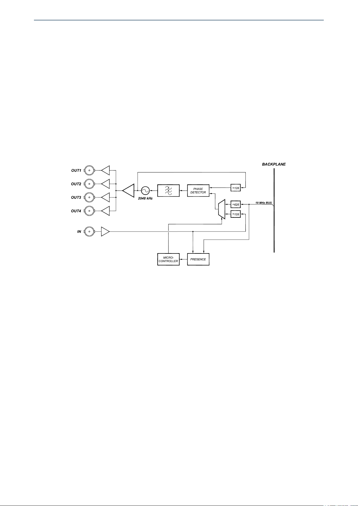
- Supervision of the status of the reference and whether or not it is locked.
4.3.1. Details of the GTI2000C01 registers
The GTI2000C01 module provides control and status registers that can be read and
written by means of specific commands described in the communication control
module user manuals.
The parameter information grouped in the CONTROL or RAM sections is stored in
volatile memory. Any modifications to the parameters will be lost when the module
power supply is disconnected unless the "EEPROM Save" button within the software
has been pressed.
The STATUS section parameters are read-only and cannot be modified.
The EEPROM section parameters are rarely used and are stored directly in non-volatile
memory.
The parameters that can be controlled and supervised remotely for each version of
the firmware are listed below:
VERSION 1.X
CONTROL
Name add ext msk snmp trap Description
ACTIVE_PRESET 0x00 0x3F Y N Shows the active preset
32=Preset 1, 33=Preset 2, 34=Preset 3, 35=Preset 4, 36=Preset 5, 37=Preset 6,
38=Preset 7, 39=Preset 8, 40=Preset 9, 41=Preset 10, 42=Preset 11, 43=Preset
12, 44=Preset 13, 45=Preset 14, 46=Preset 15, 47=Preset 16, ?=None
LOAD_PRESET 0x00 0x7F Y N Allows loading a preset
64=Preset 1, 65=Preset 2, 66=Preset 3, 67=Preset 4, 68=Preset 5, 69=Preset 6,
70=Preset 7, 71=Preset 8, 72=Preset 9, 73=Preset 10, 74=Preset 11, 75=Preset
12, 76=Preset 13, 77=Preset 14, 78=Preset 15, 79=Preset 16, ?=''
SAVE_PRESET 0x00 0xFF Y N Allows saving a preset
128=Preset 1, 129=Preset 2, 130=Preset 3, 131=Preset 4, 132=Preset 5,
133=Preset 6, 134=Preset 7, 135=Preset 8, 136=Preset 9, 137=Preset 10,
138=Preset 11, 139=Preset 12, 140=Preset 13, 141=Preset 14, 142=Preset 15,
143=Preset 16, ?=''
MODE 0x01 0x03 Y Y Allows selecting the switching mode
0=Full auto, 1=Half auto, 2=Manual
INPUT_CHG_RST 0x01 0x80 Y N Indicates a change in which input is used as reference
0=No, 1=Yes
INPUT 0x02 0x01 Y Y Allows selecting the reference input
0=Bus, 1=Front
INVERT_PRIORITY 0x04 0x01 Y N Allows changing the input priority
0=No, 1=Yes
19

Albalá Ingenieros | Manual GTI2000C01
MUTE_EN 0x04 0x02 Y N Mutes outputs when selected input is not present
0=No, 1=Yes
T_WAIT 0x05 0xFF Y N Amount of time that an input must be stable before it is considered valid and
used as reference
= x s
T_MUTE 0x06 0xFF Y N Amount of time with no valid reference before output is disabled
= x s
STATUS
Name add ext msk snmp trap Description
REAR_FAIL 0x01 0x01 Y Y Indicates lack of valid rear reference
0=OK,1=Fail
FRONT_FAIL 0x01 0x04 Y Y Indicates lack of valid front reference
0=OK,1=Fail
UNLOCK 0x01 0x80 Y Y Reference lock fail
0=OK,1=Fail
20
Table of contents
Other Albalá Ingenieros Inverter manuals
Popular Inverter manuals by other brands

Mitsubishi Electric
Mitsubishi Electric PV-PNS03ATL-GER Operation manual

SolaX Power
SolaX Power X1-0.6-S user manual

Generac Power Systems
Generac Power Systems 009600-5, 009734-5 owner's manual

KEHUA TECH
KEHUA TECH SPI-B2 Series user manual

Mitsubishi Electric
Mitsubishi Electric FR-HEL-C75K instruction manual

opti-solar
opti-solar SP5000 Premium user manual