Albalá Ingenieros DAR3000C01 User manual
DAR3000C01
AES/EBU DIGITAL AUDIO REFERENCE SIGNAL GENERATOR
Version 1.0
Albalá Ingenieros, S.A.
Medea, 4 - 28037 Madrid - Spain
12 December 2016 - © Albalá Ingenieros S.A. - All rights reserved

DAR3000C01

DAR3000C01
AES/EBU DIGITAL AUDIO REFERENCE SIGNAL GENERATOR
Version 1.0
1. DESCRIPTION ...................................................................................................................... 5
1.1. The DAR3000C01 ........................................................................................................................... 5
1.2. Features ............................................................................................................................................. 6
1.3. Block diagram .................................................................................................................................. 7
2. SPECIFICATIONS ................................................................................................................. 9
3. INSTALLATION .................................................................................................................. 11
3.1. Initial inspection .......................................................................................................................... 11
3.2. Safety instructions ...................................................................................................................... 11
3.3. Environmental considerations ................................................................................................ 12
3.4. Power considerations ................................................................................................................. 12
3.5. Module configuration ................................................................................................................ 12
3.5.1. Selection of 20 or 24 bits .................................................................................................. 13
3.5.2. Selection of the audio tone level ................................................................................... 13
3.5.3. Manual/automatic selection of the reference input .............................................. 14
3.5.4. Selection of the sampling frequency ........................................................................... 14
3.5.5. Selection of the external reference input ................................................................... 15
3.5.6. Selection of the termination for the AES/EBU reference input .......................... 15
3.6. Installing the module in the mounting frame ................................................................... 15
3.7. Interconnection ............................................................................................................................ 17
3.7.1. Digital audio connections ................................................................................................ 17
3.7.2. Analog video and word-clock connections ................................................................ 18
4. OPERATION ...................................................................................................................... 19
4.1. Front panel description .............................................................................................................. 19
4.2. Functional description ............................................................................................................... 20
4.2.1. Operating description of the external sync inputs ................................................. 20
4.2.2. Tone insertion operation .................................................................................................. 21
4.2.3. The status channel ............................................................................................................. 23
4.3. Module remote control and supervision ............................................................................. 24
4.3.1. Details of the DAR3000C01 registers ........................................................................... 25
5. GLOSSARY ........................................................................................................................ 27
6. REGULATIONS .................................................................................................................. 29
7. VERSIONS ......................................................................................................................... 31

DAR3000C01

Albalá Ingenieros | Manual DAR3000C01
1. DESCRIPTION
1.1. The DAR3000C01
The DAR3000C01 module is a digital audio reference signal generator. It includes
composite video reference inputs, digital audio reference inputs and word-clock
references inputs and can synchronize to any of them. A temperature-compensated
quartz crystal oscillator (TCXO) is provided to generate the reference signal when no
external reference source is available.
The output signal uses the AES3 format and is provided on four outputs. In addition,
there are two BNC outputs that provide the word-clock.
Synchronization to the video signal is performed as per AES11.
The reference signal delivered at the output is normally set to silence, but it can also be a
tone with an amplitude of 0 dBfs, -18 dBfs or -20 dBfs. The tone frequency can be either
400Hz or 1kHz. In addition, periods of silence can be added to the tone signal in order to
create dips for identification of the audio channels.
The module accepts reference signals of three different types: PAL or NTSC video signals
(black burst), audio sampling frequency signals (word-clock) and AES/EBU digital audio
signals as per AES11. If no signal is available at any of the inputs, the module outputs a
signal with a user-selectable frequency of 32, 44.1, 48, 64, 88.2 or 96kHz, synthesized by
the TXCO oscillator whose long-term stability is Grade 1 (frequency error is less than
1ppm).
The front panel of the module contains LEDs that indicate the reference input selected
and the synchronization status at all times.
It is possible to monitor the DAR3000C01 status remotely using a communications
controller module installed in the same mounting frame. In addition, certain controller
modules provide SNMP management and the ability to record events in a file including
date and time information for further analysis.
The DAR3000C01 is a TL3000 terminal line module and can be housed in a three rack
unit (3 RU) UR3000 mounting frame or a 1 RU UR3100 mounting frame.
5

Albalá Ingenieros | Manual DAR3000C01
1.2. Features
• High stability AES/EBU digital audio reference generator.
• Provides four transformer isolated AES/EBU digital audio outputs.
• Provides a word-clock reference output distributed to two connectors.
• Grade 1 frequency stability without external reference as per AES11 (±1ppm).
• Wide locking margin for the external reference: ±50ppm.
• Low jitter.
•Generates the following common sampling frequencies: 32kHz, 44.1kHz, 48kHz,
64kHz, 88.2kHz and 96kHz.
•All sampling frequencies generated are completely error-free with respect to the input
reference for all input references and all sampling frequencies.
•Accepts three different reference signal types: black burst, word-clock and AES/EBU
digital audio.
• Word-clock and AES/EBU outputs are phase locked.
•Digital audio reference input provides loop-through, is balanced and is transformer
isolated.
• Word-clock and black burst reference inputs provide loop-through and are coaxial.
• Silence and tone generation capabilities.
•Tones can be generated with frequencies of 400Hz or 1kHz, levels of 0, -18 and -20
dBfs and include optional dips for channel identification.
• 20 or 24 bit audio stream generation.
•Both the sampling frequency and the reference input can be selected manually or
automatically.
• Front panel indicators for external sync presence and locking.
•Module control and supervision can be done remotely when the mounting frame is
equipped with a communications controller module.
•One UR3000 mounting frame can house up to 12 DAR3000C01 modules. If power
supply redundancy is required and FA3000 or FA3001 modules are used then only 10
modules can be housed in the mounting frame. If PSU3300 or PSU3301 modules are
used for this purpose then up to 12 modules can be installed.
• One UR3100 mounting frame can house up to three DAR3000C01 modules.
• Low power.
6

Albalá Ingenieros | Manual DAR3000C01
1.3. Block diagram
7

Albalá Ingenieros | Manual DAR3000C01
DAR3000C01
8

Albalá Ingenieros | Manual DAR3000C01
2. SPECIFICATIONS
AES/EBU digital audio signal output
Connector Plug-in terminal,
3.81mm pitch
Impedance 110Ω ± 20 %
Type Transformer balanced
Encoding and electrical characteristics According to
EBU Tech. 3250-E/AES3
standard
Sampling rate 30 to 100 kHz
Number of outputs 4
Signal specifications with external reference:
Jitter <150 psRMS fs32kHz, 44.1kHz,
48kHz, 64kHz, 88.2kHz
and 96 kHz
Jitter <250 psRMS fsvarispeed
Locking range ±50 ppm
Signal specifications without external reference:
Jitter <70 psRMS
Maximum frequency error ±1ppm Grade 1 according to AES11
Black-burst reference signal input
Connector BNC
Return loss >30dB up to 5 MHz
Type Passive Loop-Through or 75Ω loaded
Signal format According to ITU-R BT.470-6 standard
Accepted formats 625i50, 525i59.94
Input signal amplitude 300mVpp ± 6 dB
AES/EBU digital audio reference signal input
Connector Plug-in terminal,
3.81mm pitch
Impedance Loop-Through or 110Ω loaded
Type Transformer balanced
Encoding and electrical characteristics According to
EBU Tech. 3250-E/AES3
standard
Sampling rate 30 to 100 kHz
Word-clock reference signal input
Connector BNC
Type Passive Loop-Through or 75Ω loaded
9

Albalá Ingenieros | Manual DAR3000C01
Sampling rate 32kHz, 44.1kHz, 48kHz,
64kHz, 88.2kHz and 96 kHz
Input level 2 - 5VPP
Word-clock reference signal output
Connector BNC
Impedance 75 Ω
Sampling rate 32kHz, 44.1kHz, 48kHz,
64kHz, 88.2kHz and 96 kHz
Number of outputs 2
Voltage levels with loaded output:
VOL max. 0.2 V
VOH min. 2.2 V
General
Maximum power supply current + 450 / - 0 mA
Operating temperature range 0 .. 50 °C
Approximate weight 325 g
10

Albalá Ingenieros | Manual DAR3000C01
3. INSTALLATION
THE DAR3000C01 MODULE CONTAINS ELECTRONIC DEVICES SENSITIVE TO
ELECTROSTATIC DISCHARGE. Always use antistatic bags clearly identified
with a high degree of shielding for storage and transportation.
The DAR3000C01 module is composed of two parts: one DAT3000P03 main board and
one DAR3000P02 rear board. Both parts must be installed in a UR3000 or UR3100
mounting frame following the instructions in the corresponding section of this chapter.
3.1. Initial inspection
Verify that the package has been properly handled during transport. After opening the
packaging, check that one DAT3000P03 main board and one DAR3000P02 rear board are
inside.
You must notify your Albalá Ingenieros distributor or dealer of any damage or defects
observed.
Follow the instructions in this manual to install this module in the mounting frame.
3.2. Safety instructions
•This equipment must be connected to a mains outlet with a protective
earth connection. Never use extension cords that do not have protective
earthing connection. The lack of an effective electrical connection between
the ground pin in the mains input connector of the equipment and the
protective earth of the electrical power distribution can cause serious harm.
•All modules of the Albalá Ingenieros TL3000 terminal line can be
hot-plugged or unplugged without suffering any damage or affecting the
processes that are currently taking place in other modules in the same
mounting frame. When a module is installed in an empty bay of a mounting
frame, it is necessary to mount the rear board that is part of that module.
Prior to installing this board, the mounting frame must be disconnected
from the power supply network. This is required because in addition to the
risk of electrocution for the person handling the device it is possible that a
high instantaneous current coming from the power supply could damage
the connectors and components of the mounting frame and/or the rear
board.
11

Albalá Ingenieros | Manual DAR3000C01
•The DAR3000C01 module and the mounting frame should always be
installed, maintained, operated and removed by personnel with sufficient
technical qualifications. The equipment should never be placed in damp
areas, near splashing liquid, or in explosive or corrosive atmospheres.
Neither modules nor mounting frames can be used in applications that
could endanger human life.
3.3. Environmental considerations
This symbol indicates that this equipment must be deposited at a collection
point for proper waste treatment once it has reached the end of its useful
life.
3.4. Power considerations
The UR3000 and UR3100 mounting frames can house as many DAR3000C01 modules as
will fit in them.
3.5. Module configuration
The DAR3000C01 module provides both microswitches and program jumpers that
should be set before installation in a mounting frame. These selectors allow the
following:
- Selection of the audio sampling bit depth to 20 or 24 bits.
- Selection of the output sampling frequency.
- Selection of the reference input.
- Selection of the level of the audio tones generated.
- Selection of loading or not for the inputs.
12
Albalá Ingenieros | Manual DAR3000C01
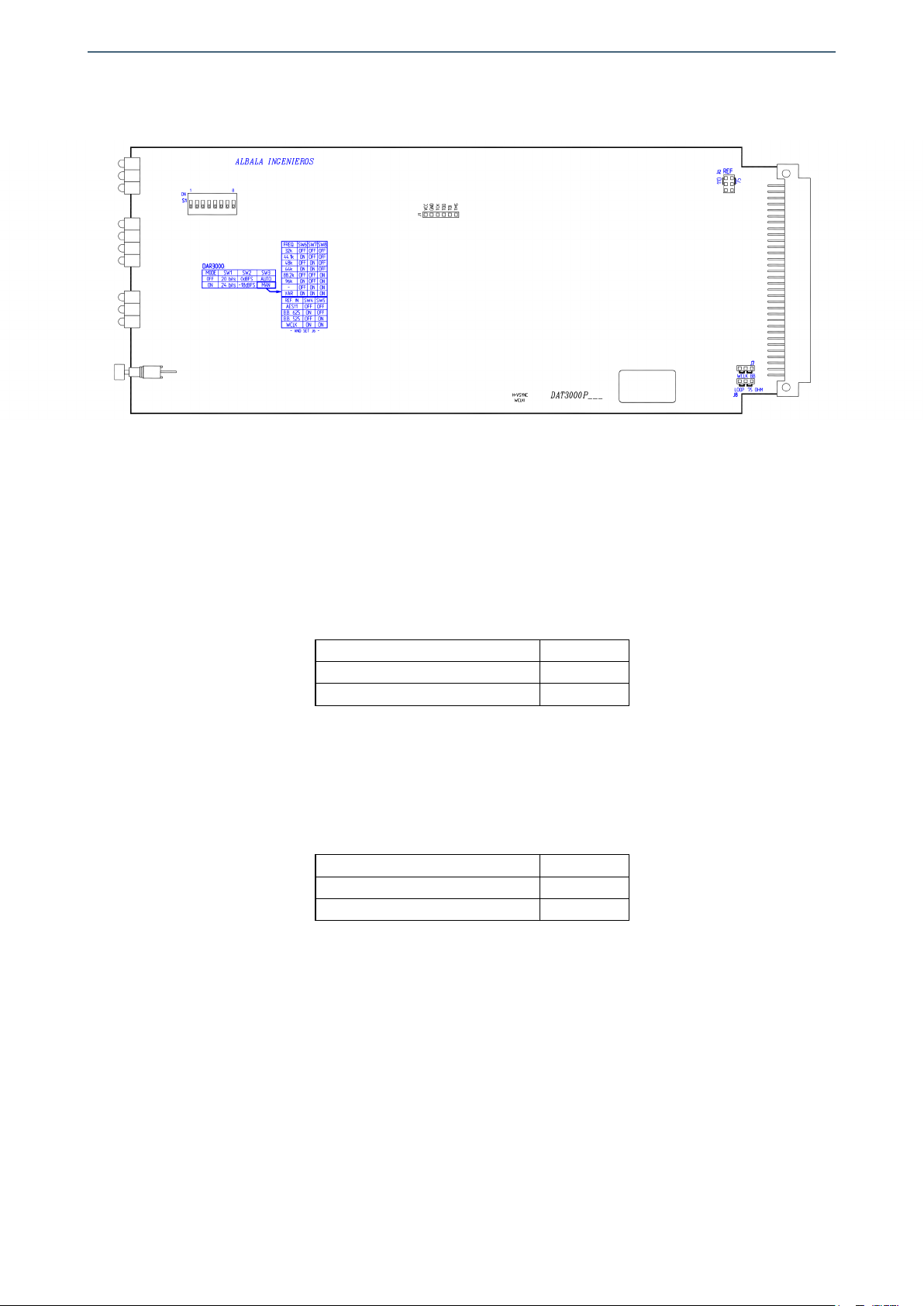
PROGRAM JUMPER AND MICROSWITCHES
POSITIONS ON THE BOARD
3.5.1. Selection of 20 or 24 bits
The DAR3000C01 module can deliver audio sampled at 20 or 24 bits in the AES/EBU
stream. This selection is made via switch 1 of S1 as shown in the following table:
MODE SW1
20 bits OFF
24 bits ON
3.5.2. Selection of the audio tone level
When the module generates audio tones, their level can be set to 0 dBfs, -18 dBfs or
-20 dBfs. This selection is made via switch 2 of S1 as shown in the following table:
LEVEL SW2
0 dBfs OFF
-18 dBfs ó -20 dBfs ON
Selection of -18 dBfs, -20 dBfs, the frequency of the audio tones and the insertion of
periods of silence for channel identification can only be done via the module's control
software, and this requires that a communications controller be installed in the same
mounting frame. The module is configured at the factory such that the ON position of
the switch 2 selects -18 dBfs.
13
Albalá Ingenieros | Manual DAR3000C01
3.5.3. Manual/automatic selection of the reference input
The DAR3000C01 module has two operating modes for selection of the reference
input and the sampling frequency: automatic or manual. In automatic mode the
reference input and the sampling frequency are adjusted automatically based upon a
set of prioritized criteria. In manual mode the user selects both the reference input
and the sampling frequency of the converter. This selection is made via switch 3 of S1
as shown in the following table:
MODE SW3
AUTOMATIC OFF
MANUAL ON
The DAR3000C01 can also function without an external reference. In such cases
manual mode should be used to select the sampling frequency and the selection of
reference input is ignored,
In manual mode, the reference input is selected using switches 4 and 5 of S1 as
shown in the following:
REFERENCE SIGNAL SW4 SW5
AES/EBU (AES11) OFF OFF
625 VIDEO lines ON OFF
525 VIDEO lines OFF ON
SPDIF-2 WORD-CLOCK ON ON
3.5.4. Selection of the sampling frequency
In automatic mode the sampling frequency of the AES/EBU signal delivered is the
same as the input reference signal the module is synchronized to. If the reference
input is a video signal, the DAR3000C01 delivers a signal with a 48kHz sampling
frequency. If a different sampling frequency at the output is desired, manual mode
should be selected and that frequency selected using switches 6, 7 and 8 of S1 as
shown in the following table:
SAMPLING FRECUENCY SW6 SW7 SW8
32kHz OFF OFF OFF
44,1kHz ON OFF OFF
48kHz OFF ON OFF
64kHz ON ON OFF
88,2kHz OFF OFF ON
96kHz ON OFF ON
VARISPEED ON ON ON
The varispeed mode only works in manual mode and with the AES/EBU reference
input. In order to use this mode, set the switches of S1 as shown in the following
table:
14

Albalá Ingenieros | Manual DAR3000C01
S1 SELECTIONS FOR VARISPEED MODE
SW1 SW2 SW3 SW4 SW5 SW6 SW7 SW8
X X ON OFF OFF ON ON ON
3.5.5. Selection of the external reference input
The word-clock and black burst external reference inputs use the same connectors on
the rear board and the type of signal that will be applied must be programmed. These
inputs provide loop-through, but they can be internally loaded with 75Ω if
loop-through functionality is not needed. These functions are programmed using
program jumpers J7 and J8 according to the diagram in the silkscreening.
3.5.6. Selection of the termination for the AES/EBU reference input
The digital audio reference input is connected using a balanced line with
loop-through. If a 110Ω termination for this line is needed, program it using jumper
J2 as shown in the silkscreening.
The DAR3000C01 comes from the factory with the following settings:
- 20 bit sampling frequency at the outputs.
- Automatic mode for selection of the reference input and the sampling frequency
- Loop-through activated for the reference inputs.
- Audio tone level of 0 dBfs.
3.6. Installing the module in the mounting frame
The steps needed to install the DAR3000C01 module with the rear board in the
mounting frame are:
1 - Disconnect all power cords from the power supplies of the mounting frame.
2 - Remove the blank panels covering the front and rear of the empty bays chosen for
installing the DAR3000C01 in the mounting frame.
3 - Install the DAR3000P02 rear board ensuring that its 12-pin connectors are properly
aligned with the mounting frame´s mating connectors. Check that the orientation of
the board is correct by looking at the placement of the text printed on it according to
the illustration below.
15
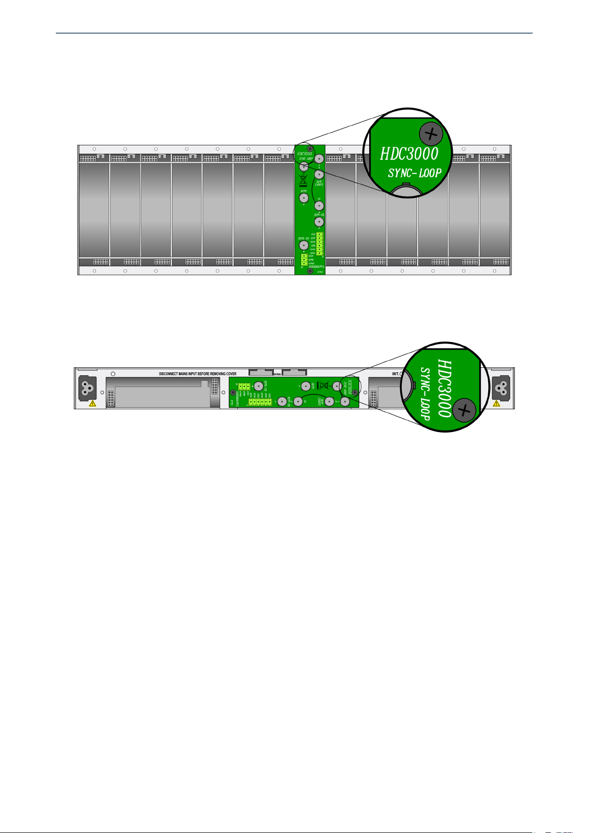
Albalá Ingenieros | Manual DAR3000C01
Details for installation of the module in 3 RU mounting frames
Details for installation of the module in 1 RU mounting frames
4 - Attach the rear board to the mounting frame with two M3 metric screws and tighten.
5 - Verify that the main board is configured according to the user requirements. The
configuration process is detailed later in the INSTALLATION section of this manual.
6 - Insert the DAT3000P03 board (main board of the DAR3000C01 module) into the front
of the mounting frame. The edges of the card slide into two plastic guides inside the
mounting frame.
7 - Affix the main board to the mounting frame using the two screws included on the
front panel.
After these steps, the module is ready to be connected to other equipment.
16

Albalá Ingenieros | Manual DAR3000C01
3.7. Interconnection
The following figure shows the DAR3000C01 module rear board connector layout.
Rear view of the DAR3000C01
The DAR3000C01 provides four digital audio reference signal outputs (OUT1,OUT2,
OUT3 and OUT4). It also includes two reference signal inputs (AES/EBU REF. LOOP IN and
REFERENCE IN (BB/WCLK)), and two audio frequency signal outputs (WORD-CLOCK OUT1
and WORD-CLOCK OUT2).
The rear interconnection board is not designed to withstand mechanical stress. The
wiring must be fastened properly to the frame where the mounting frame is housed to
prevent the rear board from supporting the weight of the cables.
3.7.1. Digital audio connections
Digital audio inputs are balanced and use 3.81mm pitch terminal block connectors.
The AES/EBU reference input provides loop-through but can be terminated with
17
Albalá Ingenieros | Manual DAR3000C01
110Ω. This loop-through input can be used to send the signal to multiple generators.
Keep in mind that this loop introduces a 0.4dB attenuation, equivalent to a loss of 5%
of the signal amplitude. Therefore, it is not recommended to have more than five
DAR3000C01 units connected using loop-through. If more than five units will be used,
the system engineer should perform the necessary calculations based upon the
length of the cabling and the signal amplitude in order to guarantee that the signal
level at the last module in the loop is always greater than 300 mVpp.
Digital audio outputs are balanced, use 3.81mm pitch terminal block connectors and
their characteristic impedance is 110Ω.
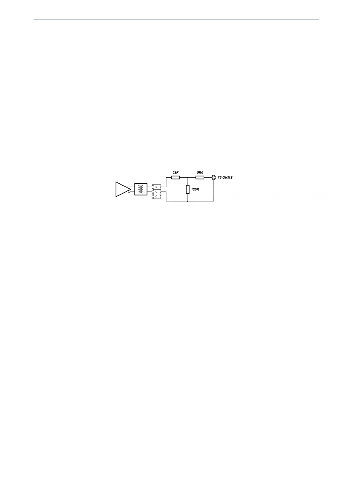
If an output signal in AES3id format is needed, an adapter as shown in the figure can
be built. Albalá Ingenieros does not provide this adapter.
TWISTED PAIR TO COAXIAL ADAPTER AS PER AES3id
For digital audio connections 110Ω characteristic impedance, two-wire shielded cable
is preferred. The GND terminal allows connection of the cable shield.
3.7.2. Analog video and word-clock connections
Coaxial cabling with a 75Ω characteristic impedance such as RG59 should be used to
connect analog video and word-clock signals.
If the loop-through feature will be used to send the signal on to other equipment,
make sure that the line is properly terminated at the endpoint.
18

Albalá Ingenieros | Manual DAR3000C01
4. OPERATION
This section describes the significance of the front panel indicators of the DAR3000C01
module and their remote control and monitoring ability.
4.1. Front panel description
The appearance of the front panel and the elements it contains are shown in the
following illustration.
Front panel of the DAR3000C01
The panel contains the following elements:
19

Albalá Ingenieros | Manual DAR3000C01
In the REFERENCE box:
AES/EBU,
CCVS,
WORD-CLK: Blue. These are the reference input indicator LEDs. Each one corresponds to
one of the three possible sync source inputs of the DAR3000C01, and they
have two brightness levels. They light up at low brightness to indicate that a
signal is present and then light up with full brightness to indicate that the
corresponding input has been selected. If an external reference is detected
but is not valid due to lack of sufficient level or an incorrect frequency then
the corresponding LED will blink.
In the SAMPLING FREQ. box:
96.0kHz,
48.0kHz,
44.1kHz,
32.0kHz: Green. These LEDs indicate the sampling frequency of the AES/EBU signal
being delivered at the outputs. Of the standard frequencies that the
DAR3000C01 can generate, only 32, 44.1, 48 and 96kHz are indicated by
these LEDs.
In the TEST box:
L,
R: Green. This LED lights up when a tone is present in the two channels of the
audio stream.
L: Green. This LED lights up when a tone is present in this channel only and the
other channel outputs silence.
R: Green. This LED lights up when a tone is present in this channel only and the
other channel outputs silence.
TEST: Pushbutton. This button selects the insertion of a test tone. If the two
associated LEDs are both off then the signal generated is of silence.
4.2. Functional description
4.2.1. Operating description of the external sync inputs
The DAR3000C01 can synchronize to three types of signals: PAL or NTSC video,
word-clock and AES/EBU digital audio. The module only has one coaxial input that is
shared for the video reference and word-clock inputs. The type of signal accepted at
the coaxial input depends on the configuration of the main board according to the
description provided in the installation section of this manual.
The module can receive external reference signals on both inputs (the AES/EBU input
20
Table of contents
Other Albalá Ingenieros Inverter manuals


