OOOO
1COOLING OPERATION (Operating room temperature range: 17 C-32 C/62 F-92 F)
- Press the POWER button to turn on the unit.
- Press the "MODE"button to select the Cool mode, the "COOL"indicator light will be turned on.
- Press the "TEMP SETTING"buttons ""or ""to select your desired room temperature.
OOOO
The temperature can be set within a range of 17 C-30 C/62 F-88 F.
- Press the "FAN SPEED"button to choose the fan speed.
- The air exhaust duct must vent outside the room when using Cool mode.
OOOO
2DEHUMIDIFYING OPERATION(Operating room temperature : 13 C-32 C/54 F-92 F)
- Press the "MODE"button to select the Dehumidifying mode, the "DRY"indicator light will be
turned on.
- Under this mode, you cannot select a fan speed, the fan motor operates at High speed only. The
temperature setting will not function also, although the temperature display will go up or down
while pressing the " " or " " buttons.
- Keep windows and doors closed for the best dehumidifying effect.
- Do not put the duct to window.
CAUTION: During Cooling and dehumidifying modes, if the compressor cycle is interrupted
(unplugged, power failure, etc.) and reinstated immediately thereafter, a compressor
protection circuit is automatically activated. The compressor cannot operate during
a compressor protection status. It may take about 3 minutes before the protection
circuit self-deactivates.(This is normal)
3 FAN OPERATION
- Press the "MODE"button to select the Fan mode, he "FAN "indicator light will be turned on.
- Press the "FAN SPEED"button to choose the fan speed. The temperature cannot be adjusted.
- Do not put the duct to window.
4 TIMER OPERATION
Setting the on timer:
- Press the "TIMER ON"button when the air conditioner is off. The "TIMER ON " indicator light will
be turned on.
- Continue pressing or keep pressing the "TIMER ON " button to select the time you need the unit
start to operate.
- The starting time is adjustable from 0 to 24 hours.
For the first 10 hours, the timer can be adjusted at half an hour interval. For the 11th hour to the
24th hour, the timer can be adjusted per hour interval. To cancel the timer setting, adjust the set
time to "0.0" .
Setting the off timer:
- Press the "TIMER OFF"button when the air conditioner is on. Continue pressing or keep pressing
the button to select the time you need the unit to be turned off. The Operation Panel Window will
display the set time for timer off.
- The turning off time is adjustable from 0 to 24 hours.
For the first 10 hours, the timer can be adjusted at half an hour interval. For the 11th hour to the
24th hour, the timer can be adjusted per hour interval. To cancel the timer setting, adjust the set
time to "0.0" .
Operating Instructions
6
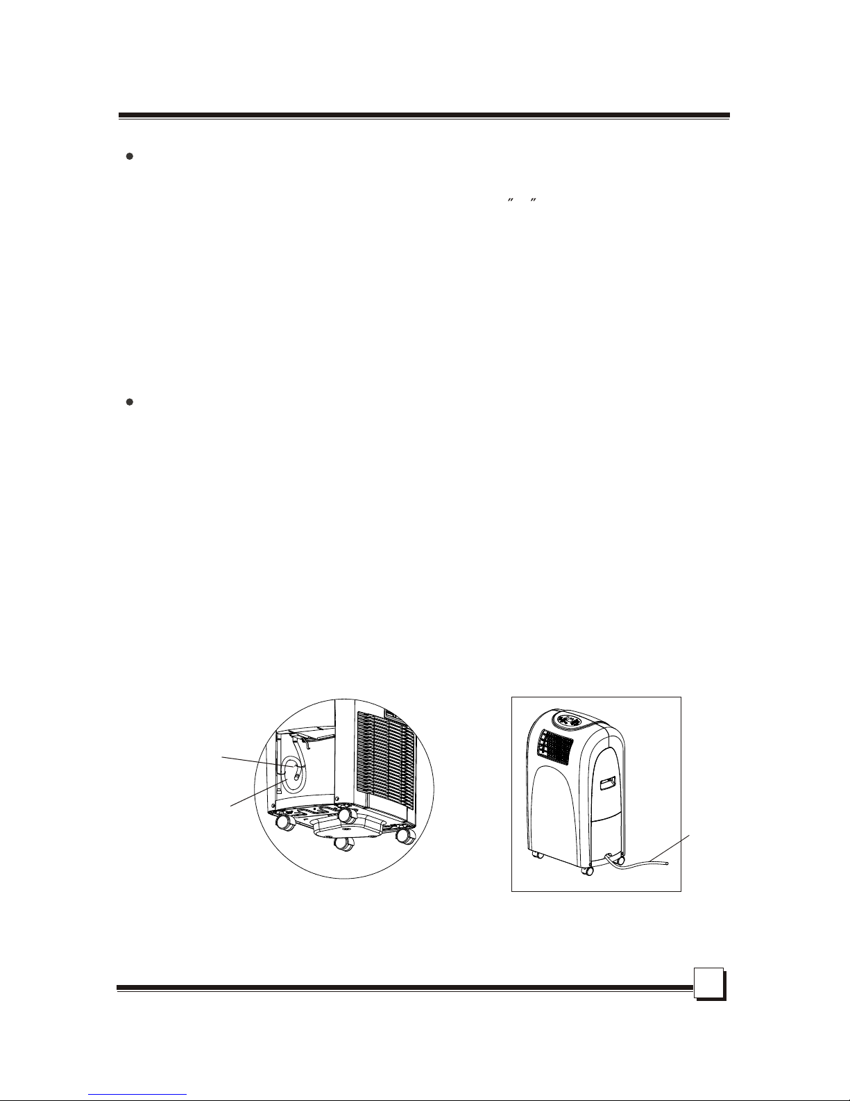
5 WATER DRAINAGE
To meet different requirement of drainage, there are two kinds of methods for your choice to
treat the condensed water. You can choose water tank drainage or continuous drainage.


 null")