3.00 Signal Paths
In the discussion of signal paths, concentration will be centered on the 3630 master
schematic. The slave functions are virtually identical to the master, the only difference being in
the way that the front panel switches control various functions. Individual switch connections are
discussed in section 3.40. Similarly, since the NanoCompressor utilizes the same basic circuitry
as the 3630, and both left and right channels function identically, only the left channel is
discussed here.
3.10 Audio Signal Paths
The input from J2 [J3] is R.F. filtered by C12 [C3] and has it's impedance set at 100K
[1M] by R12 [R1]. One section of U2 [U2] acts as a buffer/gain stage. Note that the -10/+4 switch
S2 works by adding a voltage divider element (R13) to the negative feedback path of the op-
amp (reducing negative feedback, thus increasing gain) when the switch is in the -10 position.
Also note that the NanoCompressor is permanently wired for -10 systems. The output of this op-
amp is sent to both the side chain jack J3 [J2] (and consequently on to the detectors) and to the
Voltage Controlled Amplifier (U3) [U4] via an A.C. coupling capacitor (C16) [C7] and current
limiting resistor R23 [R36]. Please note here that the VCA is a current amplifier and as a
consequence, signals present at the VCA will not be visible on an oscilloscope. The output of
the VCA is converted back into voltage mode by U2 pins12,13, and 14 [U2 pins 12, 13, and 14]
before being sent to the output via the -10/+4 switch. S2 which reduces output gain by adding
an extra voltage divider (R41, R42) when in the -10 position. Again note that the
NanoCompressor has no equivalent switch. Finally, the output is current limited to 470Ωby R26
[R5] before output jack J4 [J5].
3.20 Control Signal Paths
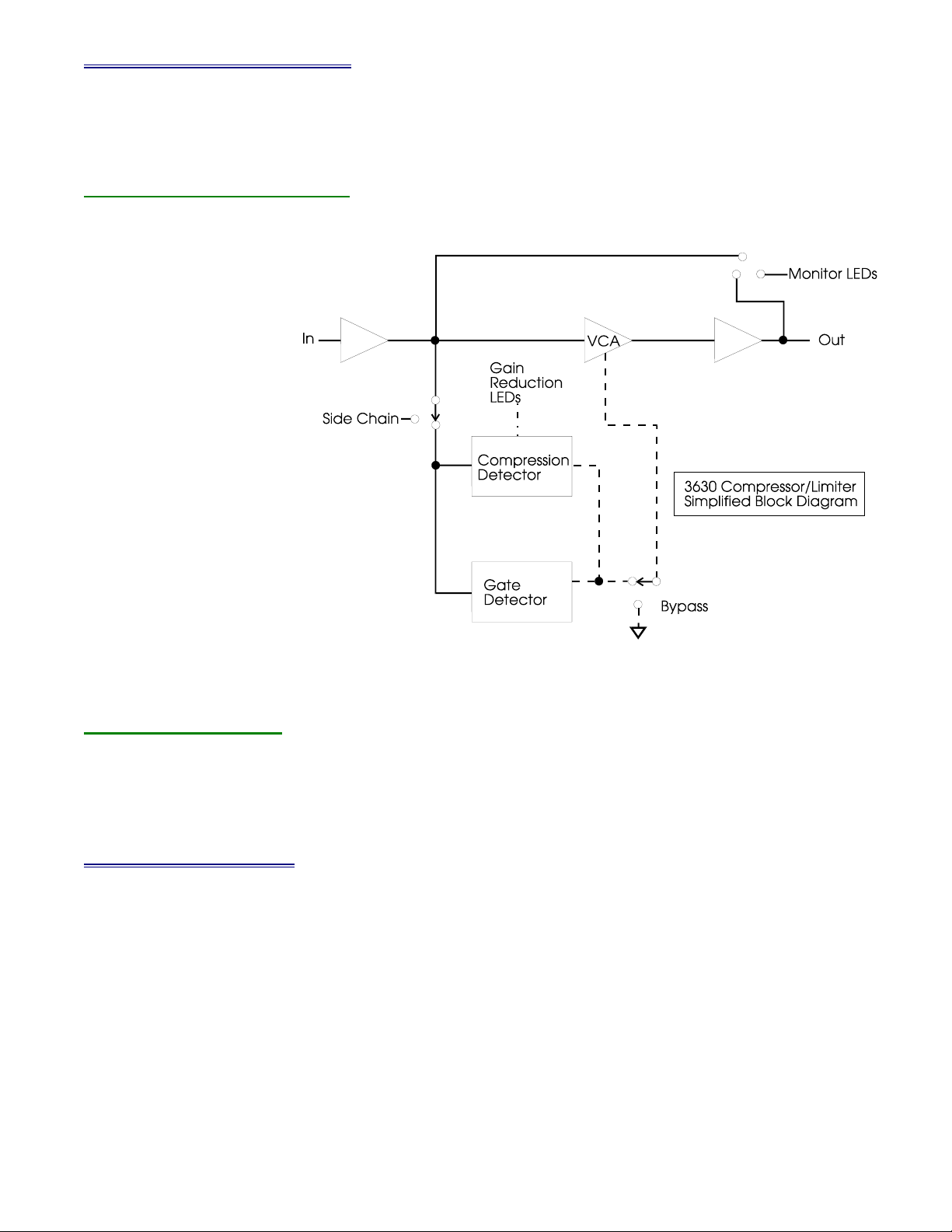
3.21 Compression Detector
The purpose of the compression detector is to vary the audio VCA control signals
according to the front panel settings of the compressor section. In the 3630, this hardware must
work in conjunction with the gate detector to produce the necessary control signal for the audio
VCAs.
The compression detector is based on the use of the 2252 RMS level detector IC U1.
[U3] The output of the detector rises roughly 6mV for every dB of input level. R7 Is used as a
symmetry adjust and should be set for minimum distortion (see section 4.10 for details). The
output of the 2252 is then sent to an active rectifier (U2 pins 5,6 and 7) [U3 pins 5,6 and 7]. The
threshold control works by biasing the input to the rectifier with a D.C. offset. The output of the
rectifier will not change until the output of the 2252 exceeds the threshold voltage set by R119
[R88]. The HARD KNEE/SOFT KNEE switch in the SOFT position incorporates R83 [R64] which
allows program material to have a greater effect on the final control voltage as well as affecting
the ratio setting.
At this point, U2 pins 1, 2, and 3 [U7B pins 5 6, and 7] provide a small amount of gain
prior to entering the envelope shaping circuitry. RC networks consisting of R121, C29, C39
[R83, C36 and C40] and R78, R122, C40 [R82, R52, C26] work in conjunction with U8 pins 1, 6,
and 7 [U6A pins 2, 4, and 5] to provide the attack/release shaping for the control signal. The
rest of the compression circuitry consists of some filtering, with R123 [R79] providing for output
gain level by adding a DC offset to the final control voltage. It is worth noting again here that the
VCA functions in current mode causing the “Control Voltage” to be unviewable using an
oscilloscope.
Alesis 3630 Compressor Service Manual 1.00 2 12/11/02