Alfalaval AlfaBlue Junior XG Series User manual

ORIGINAL INSTRUCTIONS
AHE00060EN 1904
Alfa Laval AlfaBlue Junior AG/XG
Instruction manual
• Product description
• Product labels
• Unpacking & lifting
• Installation
• Maintenance
• Spare parts

AHE00060EN 1904
2
Alfa Laval is a trademark registered and owned by Alfa Laval Corporate AB.
Alfa Laval reserves the right to change specification without prior notification.
Index
1. Important information
1.1 Disclaimer...................................................................................................................................3
1.2 Intended use...............................................................................................................................3
1.3 Where to nd product information ..............................................................................................3
2. Product description
2.1 General information and application...........................................................................................4
2.2 Standard conguration ...............................................................................................................4
2.3 Options.......................................................................................................................................4
2.4 Code description ........................................................................................................................5
3. Product labels...........................................................................................................................5
4. Unpacking and lifting
4.1 Packing.......................................................................................................................................8
4.2 Shipping dimensions ..................................................................................................................8
4.3 Feet mounting for vertical airow ...............................................................................................9
4.4 Lifting from above.....................................................................................................................10
5. Installation
5.1 Mounting dimensions ...............................................................................................................11
5.2 Concrete mounting base ..........................................................................................................17
5.3 Vibration dampers ....................................................................................................................17
5.4 Expansion joints .......................................................................................................................18
5.5 Switch on/o (option SW).........................................................................................................18
5.6 Switchboard fan speed control (option FP) ..............................................................................19
5.7 Installation layout guideline ......................................................................................................19
5.8 Electrical connections...............................................................................................................20
6. Operation
6.1 Start-up procedure ...................................................................................................................21
6.2 Shutdown .................................................................................................................................21
7. Maintenance
7.1 Fan replacement ......................................................................................................................22
7.2 End covers ...............................................................................................................................22
8. Spare parts..............................................................................................................................23

AHE00060EN 1904
3
Alfa Laval is a trademark registered and owned by Alfa Laval Corporate AB.
Alfa Laval reserves the right to change specification without prior notification.
1 Important information
1.1 Disclaimer
This Instruction Manual applies to all Alfa Laval AlfaBlue Junior AG condensers and XG gas cool-
ers and is supplied in combination with the Alfa Laval air cooled condensers & gas coolers Product
Manual AHE00049. Both manuals must be carefully examined and instructions should be followed
up at all times. Alfa Laval does not accept liability for any damage resulting from non-compliance to
the instructions as given in the manuals and order-related documents.
1.2 Intended use
Condensers and gas coolers are partly completed machinery according to Machine Directive
2006/42/EC and intended for incorporation in cooling systems. Declarations of Incorporation are
available on www.alfalaval.com. The units may not be put into operation until the conformity of the
complete machine or cooling system has been declared according to the following standards and
directives:
• Pressure Equipment Directive 2014/68/EU
• Machine Directive 2006/42/EC
• Low Voltage Directive 2014/35/EU
• Electrical Equipment of Machines IEC 60204-1
• Electro Magnetic Compatibility 2014/30/EU
• Any applicable local or national legislation
1.3 Where to find product information
Detailed technical data for individual product models are available in order related documents, on
the product label and in product data sheets. Comprehensive technical information for all Alfa Laval
air heat exchanger products is available on-line on www.alfalaval.com. This includes:
• Product manuals
• Instruction manuals
• Product leaflets & brochures
• Product data sheets (selection software)
• Dimensional drawings
• Electrical wiring diagrams
• Certificates
Alfa Laval offers world-wide service and support in over 55 countries. In case of any questions
or uncertainty please contact your local Alfa Laval representative. Contact addresses are available
at www.alfalaval.com.
AlfaBlue Junior XGAlfaBlue Junior AG

AHE00060EN 1904
4
Alfa Laval is a trademark registered and owned by Alfa Laval Corporate AB.
Alfa Laval reserves the right to change specification without prior notification.
2 Product description
2.1 General information and application
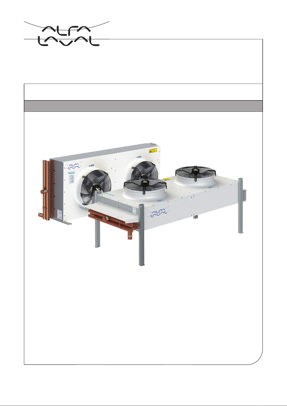
AlfaBlue Junior is a competitive condenser (AG) and gas cooler (XG) line that offers excellent per-
formance, allowing easy installation on site and an outstanding integration with other components.
High efficient fan motors combine excellent sound characteristics and low energy consumption.
AlfaBlue Junior AG condensers can be used in commercial refrigeration and HVAC installations.
AlfaBlue Junior XG gas coolers have been specifically designed for CO2refrigerant systems.
• AG condensers suitable for all HFO/HFC refrigerants.
• AG capacity range (SC2): 5.6 up to 260 kW.
• XG capacity range: 3.2 up to 230 kW
(air temp. = 35°C, CO2 at 90 bar, gas temp. in/out = 120/38°C)
2.2 Standard configuration
Finned coil:
Innovative coil design manufactured from Cu tubes (K65 for XG) and aluminium turbo fins.
Standard fin spacing 2.1 mm. Each heat exchanger is leak tested with dry air (nitrogen for XG) and
finally supplied with a nitrogen pre-charge.
Model Design pressure Test pressure
AlfaBlue Junior AG(H) 33 (45) bar 47 (65) bar
AlfaBlue Junior XG 120 bar 172 bar
Construction:
Patented coil frame design allowing thermal expansion and offering protection against vibration.
Corrosion resistant casing material, powder coated RAL9002. Separated fan sections.
Fans:
High efficiency AC or EC fans and low power consumption. Available in 3 fan diameters 350, 500
and 630 mm, different power supplies (230/50-60/1, 400/50/3, 480/60/3) and four noise levels.
Protection class IP 54 according to DIN 40050.
AC motors are fitted with integrated thermo contacts to provide reliable protection against thermal
overload (terminals in the box).
2.3 Options
• Switch on/off (SW)
• Connection box for electrical power connection (CB)
• Fan speed control 230/1 and 400/3 (FP)
• Coil options:
- Epoxy coated aluminium fins (EP)
- Seawater resistant aluminium AlMg fins (SWR)
- Copper fins (CU)
- F-coat treatment (FC)
- Industrial fins (IF)
- Fin spacing 2.5 mm. Other fin spacings on request.
• Vibration dampers (VD)
• End covers (CV)
• Mounting feet kit for vertical airflow
• Stainless steel header tubes for on-site welding connections (XG only)

AHE00060EN 1904
5
Alfa Laval is a trademark registered and owned by Alfa Laval Corporate AB.
Alfa Laval reserves the right to change specification without prior notification.
2.4 Code description
AG H S(E) 35 2 .2 A S H/V BO * - AL 2.1 CU R410A *
1 2 3 4 5 6 7 8 9 10 11 12 13 14 15 16
1 AlfaBlue Junior (AG=condenser, XG=gas cooler)
2 High pressure range for R-410A (AG only: blank=default, H=R410A)
3 Sound level/fan code (S=standard, L=low, Q=quiet, R=residential, E=EC fan motor)
4 Fan diameter (35=350, 50=500, 63=630 mm)
5 Number of fans (1 to 6)
6 Version number
7 Tube rows code (A, B, C)
8 No. of phases (S=1, D=3)
9 Units are suitable for both horizontal and vertical airflow
(mounting feet kit required for vertical airflow setup).
10 Packing (BO=box, CR=crate)
11 Options
12 Fin material (AL=aluminium, IF=industrial fins, SWR=AlMg, CU=Copper,
EP=epoxy coated aluminium, FC=F-coat)
13 Fin spacing (2.1, 2.5 mm)
14 Tube material (AG: CU=copper, XG: K65=copper K65)
15 Refrigerant (for H-execution only)
16 Options
3 Product labels
①②
⑤
③
⑨③④
⑦
⑧
⑥⑩
⑪
Spare part
item no
9460088799
2. Fan motor
Fan motor item number.
1. Electrical warning
Electrically powered component. Switch off
power supply before any maintenance or instal-
lation activity.
3. Fan direction
Sticker indicates fan rotation direction.
4. Eurovent
Sticker is applied when the product is included in
the Eurovent Certify All program.

AHE00060EN 1904
6
Alfa Laval is a trademark registered and owned by Alfa Laval Corporate AB.
Alfa Laval reserves the right to change specification without prior notification.
5. Product label
Model Refer to paragraph "Code
description"
Item ID
Serial no.
Communicate these when
ordering spare parts as
they identify the unit.
O.A. Order acknowledgement
number
Unit Net Weight Check before any lifting
operation to ensure that
proper lifting tools are
used.
6. Product label - coil
Model Refer to paraghraph "Code
description"
Item ID
Serial no.
Communicate these when
ordering spare parts as
they identify the unit.
Material Tube material
PED category According to PED
Max DN Maximum diameter of the
distributor tube
Fluid Group According to PED
Coil Ts Range of operating tem-
peratures for the coil
Ps Design pressure
Pt Test pressure
Test date Date on which the coil has
been pressure tested in
the factory
WARNING
READ INSTRUCTION MANUAL BEFORE INSTALLATION AND
MAINTENANCE TO AVOID INJURIES OR DAMAGE
Manufacturer Manuf. Date
AIR HEX ALONTE S.R.L. - Italy 04 / 2019
Model O.A. ************
AG******************
*****************
Item ID **************
Serial no. **************
Sn
Materia CU
PED Category I
Max DN 38
Fluid Group 2
Coil Ts +125/-60 °C
Ps 33 bar
Pt 47 bar
Test Date 04-2019
EXAMPLE
WARNING
READ INSTRUCTION MANUAL BEFORE INSTALLATION AND
MAINTENANCE TO AVOID INJURIES OR DAMAGE
Manufacturer Manuf. Date
AIR HEX ALONTE S.R.L. - Italy 04 / 2019
Model O.A. ***********
AG********************
*******************
Item ID **************
Serial no. **************
Unit Net Weight 146 Kg ±5%
Sn
Motorfan data
Vn 3~400V-480V
f 50/60Hz
WARNING
READ INSTRUCTION MANUAL BEFORE INSTALLATION AND
MAINTENANCE TO AVOID INJURIES OR DAMAGE
Country of origin Italy
EXAMPLE

AHE00060EN 1904
7
Alfa Laval is a trademark registered and owned by Alfa Laval Corporate AB.
Alfa Laval reserves the right to change specification without prior notification.
11. Hot surfaces
Danger of burns. Wear adequate protection.
PARTI INTERNE IN MOVIMENTO A
COMANDO AUTOMATICO.
TOGLIERE TENSIONE PRIMA DI TOCCARE
AUTOMATIC CONTROL MEANS MOVING
INTERNAL PARTS.
SWITCH OFF POWER BEFORE TOUCHING
SCHALTUNG AUF AUTOMATIK, INTERNE
BAUTEILE IN BETRIEB. VOR ARBEITSBEGINN
SPANNUNG UNTERBRECHEN
ÉLÉMENTS INTERNES A DÉMARRAGE
AUTOMATIQUE. COUPER L’ALIMENTATION
ÉLECTRIQUE AVANT INTERVENTION
Cod. 69100175
7. & 8. In/Out
Refrigerant connections inlet and outlet.
9. Moving parts
Warning: moving parts.
Switch off power supply before any mainte-
nance or installation activity.
10. Grounding
It is mandatory to ground the unit. The yellow/
green grounding wire must be left longer than
the others, to ensure that it is the last one to be
detached from the terminals in the event of the
cable being pulled off.
IN
OUT

AHE00060EN 1904
8
Alfa Laval is a trademark registered and owned by Alfa Laval Corporate AB.
Alfa Laval reserves the right to change specification without prior notification.
4 Unpacking and lifting
Always follow guidelines and instructions as given in the air cooled condensers & gas coolers prod-
uct manual AHE00049.
4.1 Packing
All units are packed and shipped in horizontal airflow position. AlfaBlue Junior 351, 352, 353, 501
and 502 units are mounted on a wooden pallet and covered with a sturdy cardboard box. All other
models are mounted on a wooden pallet, wrapped with plastic foil and covered with an open crate.
4.2 Shipping dimensions
model Standard
packing
type
Standard packing Including fan speed control switchboard
Length
cm
Width
cm
Height
cm
Volume
m3
Weight
kg
Length
cm
Width
cm
Height
cm
Volume
m3
Weight
kg
351 box 95 53 72 0,4 30 95 53 70 0,4 32
352 box 155 53 72 0,6 47 155 53 70 0,6 54
353 box 215 53 72 0,8 76 215 53 75 0,9 82
501 box 120 61 97 0,7 67 125 61 95 0,7 75
502 box 210 61 97 1,2 121 224 70 101 1,6 134
503 crate 311 70 100 2,2 208 311 70 100 2,2 226
504 crate 402 70 102 2,9 282 412 58 100 2,4 296
631 crate 177 91 135 2,2 122 177 87 127 2,0 130
632 crate 277 91 135 3,4 198 259 91 141 3,3 212
633 crate 377 91 135 4,6 296 377 91 135 4,6 310
634 crate 477 91 135 5,9 376 577 91 137 7,2 390
635 crate 577 91 135 7,1 477 559 91 141 7,2 491
636 crate 677 91 137 8,4 554 678 91 141 8,7 577
Handling can take place with use of a forklift.
Heat exchangers can be stacked during storage.
(max. 2 units).
351, 352, 353
501, 502
Other
models max. 1

AHE00060EN 1904
9
Alfa Laval is a trademark registered and owned by Alfa Laval Corporate AB.
Alfa Laval reserves the right to change specification without prior notification.
All units are packed and shipped in horizontal
airflow position. For setup with vertical airflow,
the mounting feet (kit) must be mounted prior
to installation. For this purpose the unit must be
lifted and tilted 90° onto supports. Use supports
for each mounting foot position. The supports
must span the full casing width to avoid damage
to the finned coil.
Loosen fixing bolts and remove all mounting
profiles. For AG/XG 630 models, also remove
the lifting lugs positioned on the opposite casing
side.
Replace all mounting profiles with the supplied
mounting feet. Mounting feet should be fitted on
both sides of the casing at all vacant mounting
feet and lifting lug positions.
With all mounting feet in place, the unit is ready
for further positioning and installation.
4.3 Feet mounting for vertical airflow

AHE00060EN 1904
10
Alfa Laval is a trademark registered and owned by Alfa Laval Corporate AB.
Alfa Laval reserves the right to change specification without prior notification.
Total amount of lifting points (identical for both horizontal and vertical airflow models)
351, 501, 631:
4 lifting points
352, 502, 632
4 lifting points
353, 503, 633:
4 lifting points
504, 634: 6 lifting points
635: 8 lifting points 636: 8 lifting points
30° max 30° max
side view
AlfaBlue Junior heat exchangers can be lifted
from above. For models with 2 or more fans the
use of a hoisting beam is required. AG/XG63
models are supplied with lifting lugs. For other
models eye bolts must be fitted on all lifting
points.
Attach belts or hooks to the lifting point. Respect
the allowable chain angles. The load on the lift-
ing chains shall be equally distributed on all the
lifting points.
For all heat exchanger models it is mandato-
ry to use all indicated lifting positions during
any lifting operation.
4.4 Lifting from above
M8 eye bolts
to be fitted on
AG/XG 35/50 models
(not provided)

AHE00060EN 1904
11
Alfa Laval is a trademark registered and owned by Alfa Laval Corporate AB.
Alfa Laval reserves the right to change specification without prior notification.
5 Installation
Always follow guidelines and instructions as given in the air cooled con-
densers & gas coolers product manual AHE00049.
5.1 Mounting dimensions
Drawings showing all required mounting and
refrigerant connection dimensions are available for download on
www.alfalaval.com.
Mounting dimensions model 351, 352, 353 - Horizontal airflow
Dimensional drawings
1813 ±5
1770
2020 ±10
1420 ±10
1170
1213 ±5
43
22
Ø14
FRONT VIEW
570
820 ±10
613 ±5
529 ±5
345
390
Side view (all models)Mounting profile

AHE00060EN 1904
12
Alfa Laval is a trademark registered and owned by Alfa Laval Corporate AB.
Alfa Laval reserves the right to change specification without prior notification.
Mounting dimensions model 351, 352, 353 - Vertical airflow
294
600 ±10
555
548
35
28
Ø12
TOP VIEW
Side view (all models)Mounting profile
820 ±10
570
598 ±5
1420 ±10
1170
1198 ±5
2020 ±10
1770
1798 ±5

AHE00060EN 1904
13
Alfa Laval is a trademark registered and owned by Alfa Laval Corporate AB.
Alfa Laval reserves the right to change specification without prior notification.
Mounting dimensions model 50 - Horizontal airflow
2660
2700 ±5
2965 ±10
860
900 ±5
1165 ±10
1760
1800 ±5
2065 ±10
3865 ±10
1800
3600 ±5
1760
826 ±5
420
470
Side view (all models)
40
20
Ø14
FRONT VIEW
Mounting profile

AHE00060EN 1904
14
Alfa Laval is a trademark registered and owned by Alfa Laval Corporate AB.
Alfa Laval reserves the right to change specification without prior notification.
Mounting dimensions model 50 - Vertical airflow
45
60
Ø16
TOP VIEW
Side view (all models)Mounting profile
890 ±10
420
854
899
1165 ±10
860
920 ±5
2965 ±10
2660
2720 ±5
3865 ±10
1760
1800
3620 ±5
2065 ±10
1760
1820 ±5

AHE00060EN 1904
15
Alfa Laval is a trademark registered and owned by Alfa Laval Corporate AB.
Alfa Laval reserves the right to change specification without prior notification.
5265 ±10
2000 1000 1960
5000 ±10
6265 ±10
2000 2000 1960
6000 ±10
19602000
4000 ±10
4265 ±10
3265 ±10
2960
3000 ±5
1960
2000 ±5
2265 ±10
960
1000 ±5
1265 ±10
700
750
1036 ±5
40
24
Ø14
FRONT VIEW
Side view (all models)Mounting profile
Mounting dimensions model 63 - Horizontal airflow

AHE00060EN 1904
16
Alfa Laval is a trademark registered and owned by Alfa Laval Corporate AB.
Alfa Laval reserves the right to change specification without prior notification.
6265 ±10
2000 2000 1960
6020 ±10
5265 ±10
2000 1000
5020 ±10
1960
2000 1960
4020 ± 10
4265 ± 10
2960
3020 ±5
3265 ±10
1960
2020 ±5
2265 ±10
1265 ±10
960
1020 ±5
1204 ±10
500
1057
1102
45
60
Ø16
TOP VIEW
Side view (all models)Mounting profile
Mounting dimensions model 63 - Vertical airflow

AHE00060EN 1904
17
Alfa Laval is a trademark registered and owned by Alfa Laval Corporate AB.
Alfa Laval reserves the right to change specification without prior notification.
5.2 Concrete mounting base
To avoid oxidation of the equipment feet, it
is strongly recommended to mount the heat
exchanger on concrete mounting bases. Base
dimensions as indicated.
78
M 10
128
3
30
110
9
Natural rubber, hardness 60° Sha.
5.3 Vibration dampers
45 mm
60 mm
min. 145 mm min. 160 mm
min. 100 mm
Vertical airflow
min. 140 mm
min. 100 mm
Horizontal airflow
model 35: min. 490 mm
model 50: min. 570 mm
model 63: min. 850 mm
For active and passive isolation of vibrations and
reducing noise transmission, Alfa Laval strongly
recommends the installation of vibration damp-
ers. Installation of vibration dampers must be
carried out before positioning the unit. Vibration
dampers are to be positioned between the unit
feet and the mounting base with the supplied
M10 screws.
Model Total nr. of
vibration dampers
351, 352, 353,
501, 502, 503
631, 632, 633
4
504, 634 6
635, 636 8

AHE00060EN 1904
18
Alfa Laval is a trademark registered and owned by Alfa Laval Corporate AB.
Alfa Laval reserves the right to change specification without prior notification.
5.4 Expansion joints
Alfa Laval recommends the installation of expan-
sion joints on both inlet and outlet connections.
Expansion joints are elastic elements which, if
properly installed, absorb the thermal expan-
sions of the tubing. Expansion joints are also
helpful in order to reduce vibrations in the piping.
Picture shows an installation example using
threaded bar, nut, grower washer, washer and
locknut (not supplied).
This way vibration dampers can be used to
make the cooler level adjusting the locknut. This
is particularly useful with long units or irregular
basement.
5.5 Switch on/off (option SW)
If switch on/off (SW) is selected, the default positioning is for horizontal airflow installation.
The cover design is such that it can be used both for horizontal and vertical airflow installation.
To adjust the switch positioning to the actual positioning on site: unscrew the cover fixing screws,
turn it as shown and replace fixing screws.
2xM6

AHE00060EN 1904
19
Alfa Laval is a trademark registered and owned by Alfa Laval Corporate AB.
Alfa Laval reserves the right to change specification without prior notification.
5.6 Switchboard fan speed control (option FP)
If fan speed control (FP) is selected, the default positioning of the switchboard is for vertical air-
flow installation. For application with horizontal airflow, unscrew switchboard cover and remount in
position as indicated below. The cover plate should always be positioned horizontally to protect the
electrical components.
Cover plate
Cover plate
Correct
switchboard position
horizontal airflow
Correct
switchboard position
vertical airflow
Default
switchboard position
at delivery
Incorrect
switchboard position
horizontal airflow
5.7 Installation layout guideline
Ensure installation is such that the following conditions are met:
• Place the unit outdoor, so that it can be monitored and controlled from all sides at all times.
• Ensure that sufficient space is available for maintenance.
• Verify the structures supporting capacity regarding the weight of the unit(s), including refrigerant.
• As a rule of thumb the (unrestricted) air-inlet surface area should at least equal the coil surface
of the unit(s).
• Recirculation of heated air is to be avoided at all times.
C
CC
>2C
Obstacle
Obstacle
CC
H (> B-C)
C
B
>4C
Obstacle
C
H > B
B
<4C

AHE00060EN 1904
20
Alfa Laval is a trademark registered and owned by Alfa Laval Corporate AB.
Alfa Laval reserves the right to change specification without prior notification.
C
Wind Wind
>C
> C/2
> C
C
> C/2
>C
2 units next to each other
5.8 Electrical connections
The following data determine which connection diagram is to be selected
and respected for electrical installation:
• Heat exchanger model indication
• Fan motor type
• Electrical options
Electrical connection diagrams are available for download on
www.alfalaval.com. When in doubt always contact your local Alfa Laval
representative for assistance. Electrical connections
Contact Alfa Laval to determine optimal unit spacing for specific conditions on site.
Special care should be taken in particular installations such as:
• When installation site is subjected to strong winds.
• When walls or other obstructions with different configuration than the ones shown in the previ-
ous pictures are present on site.
• When severe environmental loads are likely to affect to the unit.
This manual suits for next models
13
Table of contents
Other Alfalaval Freezer manuals
Popular Freezer manuals by other brands

Zanussi
Zanussi ZFC31401WA user manual

White-Westinghouse
White-Westinghouse WFU14FC2CW6 owner's guide

Beverage-Air
Beverage-Air TMF Series Installation and operating instructions

Electrolux
Electrolux TF633 Installation and use

Electrolux
Electrolux IK2480BNR user manual

SMC Networks
SMC Networks HRGC001-A Series Service manual