All-Star Products ALL-STAR HB Series Instruction Manual

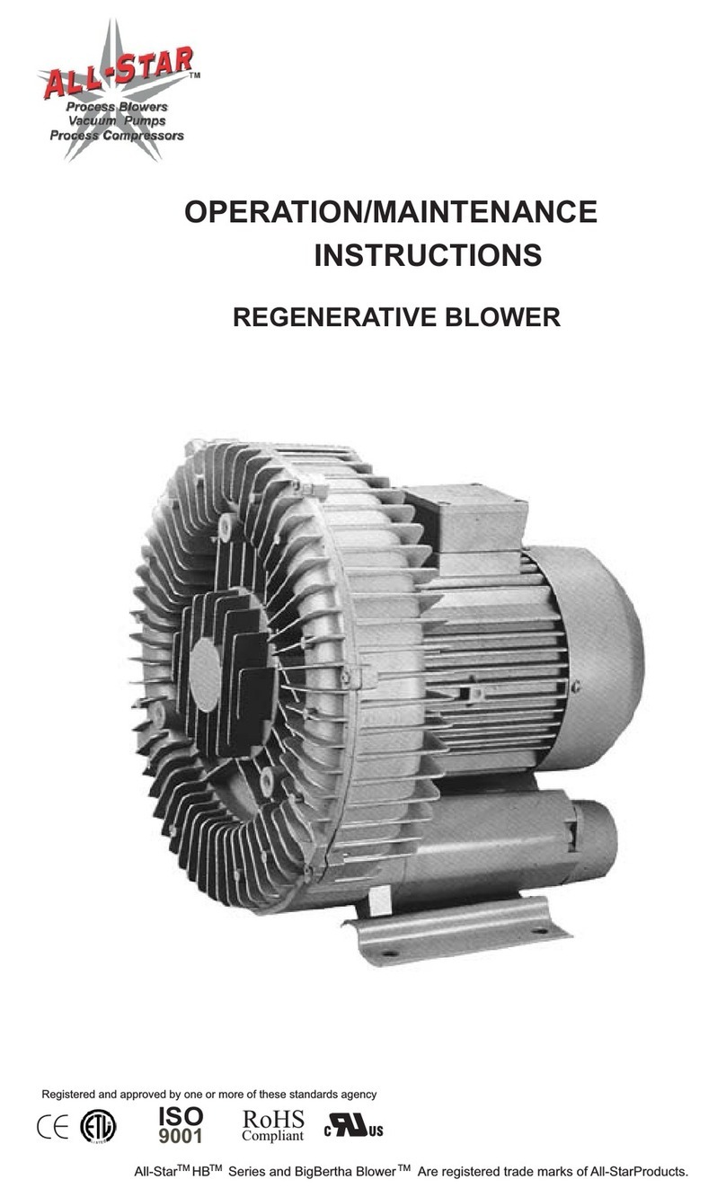
OPERATION / MAINTENANCEINSTRUCTIONSALL-STARTurboBlowerTMAll-Star HB Series and Big Bertha Blower are registered trademarks of All-Star Products.TMTMTM

1 INTRODUCTION!To insure safe operation of your All-Star blower, please read this instruction manual and pay particular attention to instructions marked with the following signs:!!DANGER Indicates an imminently hazardous situation which, if not avoided, will result in death or serious injury.WARNING Indicates a potentially hazardous situation, which, if not avoided, could result in death or serious injury.CAUTION Indicates a potentially hazardous situation, which, if not avoided, may result in minor or moderate injury.1.1 ApplicationThe All-Star blower is a complete unit, ready for immediate installation. It is designed for handling air and other non-flammable, non-corrosive and non-explosive gasses only.1.2 Blower PressureThe drive motor can be loaded to the total differential pressuregiven in the Technical Data table. 1.3 TemperatureThe maximum permissible ambient temperature and gas temperature at the inlet is 40 degree C (104 degree F). Forhigher temperature use, refer to the factory.

1.4 Performance SpecificationsAll blower motors are 2 pole design and operate at approximately 3450 rpm at 60HZ.Motors are suitable for operation on 3/50/220/380. Motor nameplate currents varyfrom time to time. If the current listed below is different from the current on your motor nameplate, use the nameplate current for sizing and selection purposes. HPVoltageCurrentMaximumPerformanceSounddb(A)Wtlbs SCFM “H2OModel NoTB05-3*TB1-3*TB205-3**TB305-3TB5-3* Available in 1/60/50/115/230 volts ** Available in 1/60/50/239 volts½12.53.55208-230/460208-230/460208-230/460208-230/460208-230/4602.2/2.0/1.03.5/3.2/1.66.8/6.2/3.19.2/8.3/4/114.8/13.4/6.75.910.412.61515.7315675800140017253.9”4.9”4.9”5.9”5.9”70809096100406688133164Intake
mm H OkPa2
40801201602002402803203604000.40.81.21.62.02.42.83.23.64.00AIR FLOW SCFM15030045060075090010501200135015001650CMM1721.325.529.83438.342.546.812.88.54.3
PRESSUR
E
24681012“H2O141660Hz Pressure

!2 OPERATION2.1 Transport and StorageWhen lifted by crane, All-Star blowers must be secured at the eyebolt on the pump casing.Attention should be paid to the load-bearing capacity of the hoisting equipment.2.2 InstallationAll-Star blowers can be installed and mounted in any horizontal orvertical position. Quiet vibration-free running is achieved by insuring the blower is mounted onto a firm foundation or structure.Keep ventilation gratings and opens clear. The direction of flow isindicated by an arrow on the silencer housing.WARNING On installation or after maintenance, it is required to check that the blower rotation is correct before returning to service.WARNING Do not operate the blower with the outlet blocked or restricted.!2.3 Electrical ConnectionDANGER The electric power must be disconnected before any work is performed on the blower or associated equipment.The system voltage and frequency must be the same as statedon the blower nameplate. +/- 5% voltage and +/- 2% frequencyvariations are permissible without affecting the blower perform-ance. The incoming electrical power should be connectedaccording to the wiring diagram located in the conduit box cover.The protective earth conduction should be connected tothe terminal.!

CAUTION High surface temperatures of more than 70 Deg C (158 Deg F) can occur on the blower's surface. No heat-sensitive parts such as normal electrical leads or electronic components can make contact with or be attached to the blower. Warning signs and protective screens must be installed around the blower surfaces to prevent accidental contact by individuals.The rated motor currents are based on 40 Deg C gas inlet andambient temperature.Select motor circuit breakers to match the rated motor current.All-Star blowers are suitable for operation on VFD (variable frequencydrives). Shielded power leads are recommended to control high frequency currents and voltage harmonics that cause electromagneticinterference.Exceeding the rated operating speed (3450 rpm), causes increasednoise, vibration, heat and reduces the life of bearing lubricant. Ifthe blower is to operate at higher speeds, the manufacturershould be contacted.!!2.4 CommissioningCAUTION The blower must not be operated with the intake or outlet closed or blocked.!CAUTION If the blower is started without being bolted to a mounting base, the initial starting torque of the motor may cause the blower to move suddenly and possibly topple over.For safe operation, the following conditions, as a minimummust be followed:The blower should be assembled and operated according tothe data on the nameplate.When VFDs are used, operating speeds are not to be exceededunless the blower has been specifically designed for VFDoperation.The blower is property assembled, aligned and connected topiping and/or hosing.

3.0 Lubrication!DANGER Before any work is performed on the blower, equipment and especially when removing covers on moving parts, the motor needs to be disconnected from the electrical power supply.!DANGER Do not connect the electrical power supply until the blower and other equipment have been completely reassembled.3.13.2Shielded and open bearings require relubrication. The frequency of replacing the grease depends upon the application. As a guideline, in normal clean environments with less than a 40 Deg C ambient, bearings should be lubricated after approximately 20,000hours of service or prior to 2.5 years. If service conditions are dusty, dirty or include high operating temperatures, bearings shouldbe lubricated more frequently.Bearing TypesGrease TypesAll-Star blowers utilize standard Shell Albida LC, -30 Deg F to+ 320 Deg F, although other lubricants can be used from time to time and is therefore subject to change. Lubricants of different manufacturers should not be mixed. If changing lubricant types, the bearing and housing should be thoroughly cleaned to removeall lubricant before adding grease from a new supplier.!WARNING On installation or after maintenance, it is required to check that the blower rotation is correct before returning to service.WARNING Do not operate the blower with the outlet blocked or restricted.!

!DANGER Covers which prevent contact with rotating parts are not to be opened during operation.4 MAINTENANCE!DANGER Before any work is performed on the blower, equipment and especially when removing covers on moving parts, the motor needs to be disconnected from the electrical power supply.!DANGER Do not connect the electrical power supply until the blower and other equipment have been completely reassembled.4.1 CleaningThe surface of the blower should be clean and free from dust orother contaminants. Surface dust can be blown with a lowpressure air hose or supply periodically to prevent a build-up ofmaterial.When required by the operating conditions, dismantle the coverfrom the blower by removing the screws or nuts from the cover.Do not lose the screws or nuts, they are required for reassembly.Remove and clean the cover. Clean impeller and the internalportion of the blower with low pressure air after covering therolling contact bearing and bearing grease housing. Be carefulnot to blow any dirt or contaminants into the bearing grease. Ifdirt enters the lubrication or bearing, remove the contaminatedgrease, clean the bearing and replenish with new grease.!WARNING After removing the blower cover screws or nuts, some parts held with centering fits and can suddenly separate, fall and possibly cause injury and damage to the parts. Care needs to be taken during disassembly to insure all parts are securely held in place.!DANGER Covers which prevent contact with rotating parts are not to be opened during operation.

4.2 TroubleshootingMotor does not start,no rotor noise.Motor does not start, humming noiseMotor-protectivecircuit breaker tripsagain after motor isswitched on, power consumption too highNo pressure orpressure is weakCompressor is notairtight.At least two powersupply conductorsinterruptedInterruption in one powersupply conductorImpeller jammedImpeller defectiveBearing defectiveShort circuit inthe windingMotor overloadedCompressor jammedLeak in the systemWrong direction ofrotationCompressor too smallSealing disc defectiveProblemCauseCorrective StepsEliminate interruption bymeans of fuses, terminals or lead feeder.See "Motor does not start,no running noise."Open cover, remove foreignmatter, clean; if necessary,check impeller gap andadjust if necessaryReplace impellerReplace bearingInspect motor windingReduce operating pressure,clean filter, silencer, connecting pipes.See "Motor does not start,humming noise."Make system airtightChange direction ofrotationUse larger compressorFit new shaft sealConfirm calculationsClean impellerReplace worn impeller.Inspect sealing disc

Part No12345678910111213141516171819202122232425262728DescriptionFlange CoverInlet FlangeInlet ScreenFront CoverImpeller WasherImpellerSealing SleeveSleeveHousingOutlet FlangeRubber SealMotor Joint CoverFront BeearingInner Bearing CoverKeyRotorStatorMotor HousingBack BearingSpring WasherMotor EndbellMotor Cooling FanCooling Fan CoverTerminal BoxTerminal BoxTerminal Box SealTerminal Box CoverPower Cabel Connector
TurboBlower
26252423272221201918171619876151413121154321

CONNECTION DIAGRAMThe blower is designed to operate on:60HZ Single Phase 115/230 volts 50HZ Single Phase 220 volts Three Phase 208, 230, 460 volts Three Phase 220, 380 voltsSingle phase motors include two types of thermal protectors, which can be connectedin several methods. If you have any questions, refer to the All Star Products.Thermal Protector Type 1. This thermal device is used in all single phase motors.The thermal protector is connected to two black unmarked wires in the conduit box. 2) Connect the two black wires as shown below for manual re-start of the blower motor.V1U1U2W2V2W1CAPACITORV1U1U2W2200 to 240 voltsV2W1CAPACITORTHERMALTHERMAL100 to 120 volts1) To disable the thermal protector, connect the two black wires as shown below.3) Connect as shown below for auto-restart of the blower motor for .25, .33 and .67HP blowers only. CAUTION: When using this connection, the motor will restart automatically and can cause damage to machinery or injury to individuals. All installations wired in this manner require posting of information regarding the possible dangers regarding auto restarting of the machinery or equipment.V1U1U2W2V2W1CAPACITORV1U1U2W2200 to 240 voltsV2W1CAPACITORTHERMAL100 to 120 voltsBlackTHERMALBlackV1U1U2W2200 to 240 voltsV2W1CAPACITORV1U1U2W2100 to 120 voltsV2W1CAPACITORTHERMALTHERMALBLUEWHITEBLACKBLUEXBLACKWHITExxxx

THREE PHASE MOTOR CONNECTION DIAGRAMW2U2V2U1V1W1DELTA CONNECT220 (208-240)W2U2V2U1V1W1WYE CONNECT460 (380-460)YLCUGTYBFMDWRKHENADIMENSIONSMODELTB-05-3TB1-3TB2-3TB305-3TB5-3A5.35.35.55.513.8B5.36.56.57.679.45C4.64.926.107.287.87D8.269.9210.3511.0213.78E7.287.487.489.0516.33F7.289.059.6411.0211.22G2.762.633.263.944.52H7.999.6410.5211.9312.80K14.7617.7119.2921.2524.60L13.9814.4517.1319.4921.26M15.5517.7119.4921.6525.39N4.56.026.146.493.97R.39.51.51.63.63T.47.59.59.59.78U3.934.924.927.087.08W3.64.55.35.95.9Y1.962.162.763.352.56

For more detailed information, visit http://www.all-star-usa.comAll-Star Products IncSales Office & Warehouse2095 Exeter Rd Ste 80-324 Memphis TN 38138Tel 800-431-8258 Tel 901-755-9613 Fax 901-758-0816[email protected]All Star blowers are high quality engineered and manufactured blowers. They are designed to meet international standards and have received approvals andrecognition from the following agencies.All-Star Products warrants all of its products against defects in material and workmanship for a period of one (1) year from the date the product is placed in service to a maximum of eighteen (18) months from the date of shipment, whichever occurs first. Purchaser is responsible for providing adequate and approved storage during the 18 month period. Nothwithstanding the foregoing, any equipment or components of the products not of All-Stars Products own manufacture and/or specified by the purchaser, is sold under only such warrantyas the maker thereof extends to All-Star Products and All-Star Products is able to enforce, but such items are not warranted by All-Star Products in any way. All Star Products is not responsible for product failures caused by the purchaser or their customer misapplying the product, operating the product beyond the published ratings and values, misuse, field alterations and changes, lack of proper mainte-nance or improper storage, neglect or accident are also excluded from this Limited Warranty. This Limited Warranty is effective, provided (1) The purchaser immedi-ately notifies All-Star Products in writing of the alleged defect after it becomes known to the purchaser and (2) No alterations, repairs or services have been performed by the purchaser or third parties on the product, without the written approval of an officer of All-Star Products (3) a properly size intake air filter is installed. This Warranty is in lieu of all other expressed or implied warranties, including any warranty of merchantability or fitness for any purpose.The warranty does not cover misuse or misapplication, abuse, neglect or other causes of failure beyond the manufacture's control. Do not disassemble or try to repair the blower/pump or any component. Any attempt to repair or correct a problem by you or your agent will void your warranty. A disassembled unit will not be considered as a warranted failure under any circumstance.Warranty
This manual suits for next models
6
Table of contents
Other All-Star Products Blower manuals
