Allen-Bradley ControlNet 1786-6.2.1 Technical manual

Planning and
Installation
Manual
ControlNet
Coax Cable
System
(Cat. No. 1786-6.2.1)
Allen-Bradley

Important User
Information Because of the variety of uses for the products described in this
publication,thoseresponsiblefortheapplicationanduseofthiscontrol
equipment must satisfy themselves that all necessary steps have been
takentoassurethateachapplicationand usemeetsallperformanceand
safetyrequirements, including any applicable laws, regulations, codes
and standards.
The illustrations, charts, sampleprogramsand layout examplesshown
in this guide are intended solely for purposes of example. Since there
are many variables and requirements associated with any particular
installation, Allen-Bradley does not assume responsibility or liability
(to include intellectual property liability) for actual use based upon the
examples shown in this publication.
Allen-Bradley publication SGI-1.1, Safety Guidelines for the
Application, Installation, and Maintenance of Solid-State Control
(available from your local Allen-Bradley office), describes some
important differences between solid-state equipment and
electromechanicaldevicesthatshouldbetakenintoconsiderationwhen
applying products such as those described in this publication.
Reproduction of the contents of this copyrighted publication,in whole
orin part, withoutwrittenpermissionofAllen-BradleyCompany,Inc.,
is prohibited.
Throughout this manual we use notes to make you aware of safety
considerations:
Attention statements help you to:
•identify a hazard
•avoid the hazard
•recognize the consequences
Important: Identifies information that is critical for successful
application and understanding of the product.
ControlNet is a trademark of ControlNet International Ltd.
PLC, PLC-5/20C, and PLC-5/40C are trademarks of Allen-Bradley Company, Inc.
!ATTENTION: Identifiesinformationaboutpractices
or circumstances that can lead to personal injury or
death, property damage or economic loss.

Publication 1786-6.2.1 - April 1998
Preface P-1
About This Manual
Manual Contents Use this manual to plan and install a ControlNet™cable system.
This manual describes the required components of the cable system
and how to plan for and install these required components.
Important: We assume that you have a fundamental understanding
of electronics and electrical codes.
Abbreviations
To: Read chapter:
Understand the ControlNet Coax cable system 1
Plan a ControlNet Coax cable system 2
Install a ControlNet Coax cable system 3
For reference on: See appendix:
Mounting dimensions (taps, universal mounting bracket,
and repeater)
A
Adjusting the cable strip tool B
Abbreviation Means
PVC cable polyvinyl chloride cable
FEP cable fluorinated ethylene propylene cable
PLC processor Allen-Bradley programmable logic controller
network continues (other nodes not shown)

P-2 About This Manual
Publication 1786-6.2.1 - April 1998
Related Publications
Publication Publication Number
ControlNet Cable System Component List
AG-2.2
Industrial Automation Wiring and Grounding Guidelines
1770-4.1
ControlNet Communication Interface User Manual
(parallel/serial interface, 1770-KFC) 1770-6.5.20
ControlNet 1771 Adapter Module User Manual
1771-6.5.110
1771-ACN(R) Installation Instructions
1771-6.5.124
ControlNet Communication Interface Card Installation
Instructions
(PC interface, 1784-KTC, -KTCX) 1784-5.20
KTCX15 Installation Instructions 1784-5.33
ControlNet PLC-5 Programming Software Instruction Set
Reference Manual
1785-6.1
1785 PLC-5 Programmable Controller Design Manual
1785-6.2.1
Enhanced & Ethernet PLC-5 Programmable Controllers User
Manual
1785-6.5.12
ControlNet PLC-5 Programmable Controllers User Manual
1785-6.5.14
1785 PLC-5 Programmable Controllers Quick Reference
1785-7.1
ControlNet PLC-5 Programmable Controllers Quick Start
1785-7.4
ControlNet PLC-5 Quick Start
1785-10.6
ControlNet Coax Tap Installation Instructions
1786-2.3
ControlNet Network Access Cable Installation Instructions
1786-2.6
ControlNet Repeater Installation Instructions
1786-2.7
ControlNet Release 1.5 System Overview
1786-2.12
ControlNet Coax Taps Installation Instructions
1786-5.7
ControlNet Coax Repeater Installation Instructions
1786-5.8
ControlNet High-flex RG-6 Coax Cable Installation Instructions
1786-5.9
ControlNet BNCJI Connector Installation Instructions
1786-5.14
ControlNet Tap Dummy Load Installation Instructions
1786-5.15
Flex I/O ControlNet Adapter Installation Instructions
1794-5.8
1794-ACN(R) Installation Instructioins
1794-5.47
PLC-5 Programming Software Configuration and Maintenance
Manual
6200-6.4.6
PLC-5 Programming Software Programming Manual
6200-6.4.7
PLC-5 Programming Software Instruction Set Reference
Manual
6200-6.4.11
PLC-5 Programming Software I/O Configuration Manual
6200-6.4.12
PLC-5 Programming Software Supplement —
ControlNet Support
6200-6.4.20

Table of Contents
Publication 1786-6.2.1 - April 1998
Chapter 1
Overview Of The ControlNet
Cable System
Contents . . . . . . . . . . . . . . . . . . . . . . . . . . . . . . . . . . . . . . . . . . . 1-1
Understanding The ControlNet Cable System. . . . . . . . . . . . . . . . 1-1
Understanding ControlNet Components . . . . . . . . . . . . . . . . . . . . 1-2
Nodes . . . . . . . . . . . . . . . . . . . . . . . . . . . . . . . . . . . . . . . . . . 1-2
Taps. . . . . . . . . . . . . . . . . . . . . . . . . . . . . . . . . . . . . . . . . . . . 1-3
Trunk Cable . . . . . . . . . . . . . . . . . . . . . . . . . . . . . . . . . . . . . . 1-3
Cable Connectors. . . . . . . . . . . . . . . . . . . . . . . . . . . . . . . . . . 1-4
Terminators . . . . . . . . . . . . . . . . . . . . . . . . . . . . . . . . . . . . . . 1-4
Segments. . . . . . . . . . . . . . . . . . . . . . . . . . . . . . . . . . . . . . . . 1-4
Repeaters . . . . . . . . . . . . . . . . . . . . . . . . . . . . . . . . . . . . . . . 1-5
Links . . . . . . . . . . . . . . . . . . . . . . . . . . . . . . . . . . . . . . . . . . . 1-5
Bridge . . . . . . . . . . . . . . . . . . . . . . . . . . . . . . . . . . . . . . . . . . 1-6
Network. . . . . . . . . . . . . . . . . . . . . . . . . . . . . . . . . . . . . . . . . 1-6
Next . . . . . . . . . . . . . . . . . . . . . . . . . . . . . . . . . . . . . . . . . . . . . . 1-6
Chapter 2
Planning A ControlNet Cable
System
Contents . . . . . . . . . . . . . . . . . . . . . . . . . . . . . . . . . . . . . . . . . . . 2-1
Determining How Many Taps You Need. . . . . . . . . . . . . . . . . . . . 2-1
Connecting Programming Devices. . . . . . . . . . . . . . . . . . . . . . . . 2-2
Determining What Type Of Cable You Need . . . . . . . . . . . . . . . . . 2-3
Determining Trunk-Cable Section Lengths . . . . . . . . . . . . . . . . . 2-4
Determining How Many Terminators You Need . . . . . . . . . . . . . . 2-5
Determining If You Need Repeaters. . . . . . . . . . . . . . . . . . . . . . . 2-6
Configuring Your Link With Repeaters . . . . . . . . . . . . . . . . . . 2-7
Installing Repeaters In Series . . . . . . . . . . . . . . . . . . . . . . 2-8
Installing Repeaters In Parallel . . . . . . . . . . . . . . . . . . . . . 2-9
Installing Repeaters In A Combination Of Series And
Parallel . . . . . . . . . . . . . . . . . . . . . . . . . . . . . . . . . . . 2-10
Determining What Type Of Connectors You Need . . . . . . . . . . . 2-11
Using Redundant Media (optional) . . . . . . . . . . . . . . . . . . . . . . . 2-12
Application Considerations . . . . . . . . . . . . . . . . . . . . . . . . . . . . 2-14
General Wring Guidelines . . . . . . . . . . . . . . . . . . . . . . . . . . . 2-15
Wiring External To Enclosures . . . . . . . . . . . . . . . . . . . . . 2-15
Wiring Inside Enclosures . . . . . . . . . . . . . . . . . . . . . . . . . 2-15
Surge Suppression . . . . . . . . . . . . . . . . . . . . . . . . . . . . . 2-16
Ferrite Beads. . . . . . . . . . . . . . . . . . . . . . . . . . . . . . . . . . 2-16
Ordering Components . . . . . . . . . . . . . . . . . . . . . . . . . . . . . . . . 2-17
General Planning . . . . . . . . . . . . . . . . . . . . . . . . . . . . . . . . . 2-17
Segment Planning . . . . . . . . . . . . . . . . . . . . . . . . . . . . . . . . 2-17
Link Planning . . . . . . . . . . . . . . . . . . . . . . . . . . . . . . . . . . . . 2-17
Ordering Parts . . . . . . . . . . . . . . . . . . . . . . . . . . . . . . . . . . . 2-18
ii Table of Contents – ControlNet Coax Cable Planning and Installation Manual
Publication1786-6.2.1 - April 1998
Next . . . . . . . . . . . . . . . . . . . . . . . . . . . . . . . . . . . . . . . . . . . . . 2-18
Chapter 3
Installing A ControlNet Cable
System
Contents . . . . . . . . . . . . . . . . . . . . . . . . . . . . . . . . . . . . . . . . . . . 3-1
Installing The Trunk Cable . . . . . . . . . . . . . . . . . . . . . . . . . . . . . . 3-1
Wiring External To Enclosures . . . . . . . . . . . . . . . . . . . . . . . . 3-1
Wiring Inside Enclosures. . . . . . . . . . . . . . . . . . . . . . . . . . . . . 3-1
Mounting The Taps . . . . . . . . . . . . . . . . . . . . . . . . . . . . . . . . . . . 3-2
Selecting Where To Mount The Taps. . . . . . . . . . . . . . . . . . . . 3-2
Mounting The Taps. . . . . . . . . . . . . . . . . . . . . . . . . . . . . . . . . 3-2
Mounting A Tap Using A Universal Mounting Bracket. . . . . 3-3
Mounting A Tap Through The Body Holes . . . . . . . . . . . . . 3-4
Installing a Repeater . . . . . . . . . . . . . . . . . . . . . . . . . . . . . . . . . . 3-4
European Union Directive Compliance . . . . . . . . . . . . . . . . . . 3-5
EMC Directive . . . . . . . . . . . . . . . . . . . . . . . . . . . . . . . . . . 3-5
Low Voltage Directive . . . . . . . . . . . . . . . . . . . . . . . . . . . . 3-5
Selecting Where To Mount The Repeater(s) . . . . . . . . . . . . . . 3-5
Mounting The Repeater . . . . . . . . . . . . . . . . . . . . . . . . . . . . . 3-6
Grounding The Repeater. . . . . . . . . . . . . . . . . . . . . . . . . . . . . 3-6
Connecting Power And Relay Circuitry . . . . . . . . . . . . . . . . . . 3-7
Installing Cable Connectors . . . . . . . . . . . . . . . . . . . . . . . . . . . . . 3-9
Collecting Your Tools . . . . . . . . . . . . . . . . . . . . . . . . . . . . . . . 3-9
Stripping The Cable . . . . . . . . . . . . . . . . . . . . . . . . . . . . . . . 3-10
Testing For Electrical Shorts And Continuity . . . . . . . . . . . . . 3-14
Attaching The Connectors To The Cable . . . . . . . . . . . . . . . . 3-15
Testing For Electrical Shorts and Continuity . . . . . . . . . . . . . 3-17
Connecting Cable Sections . . . . . . . . . . . . . . . . . . . . . . . . . . . . 3-18
Terminating Segments . . . . . . . . . . . . . . . . . . . . . . . . . . . . . . . 3-18
Connecting Devices. . . . . . . . . . . . . . . . . . . . . . . . . . . . . . . . . . 3-19
Connecting Programming Terminals Through NAP . . . . . . . . 3-19
Connecting The Repeater To A ControlNet Link. . . . . . . . . . . 3-21

Table of Contents – ControlNet Coax Cable Planning and Installation Guide iii
Publication 1786-6.2.1 - April 1998
Appendix A
Mounting Dimensions Contents . . . . . . . . . . . . . . . . . . . . . . . . . . . . . . . . . . . . . . . . . . . A-1
Taps . . . . . . . . . . . . . . . . . . . . . . . . . . . . . . . . . . . . . . . . . . . . . . A-1
Universal Mounting Bracket. . . . . . . . . . . . . . . . . . . . . . . . . . . . . A-2
Repeater . . . . . . . . . . . . . . . . . . . . . . . . . . . . . . . . . . . . . . . . . . . A-2
Appendix B
Adjusting The Cable Strip
Tool
Contents . . . . . . . . . . . . . . . . . . . . . . . . . . . . . . . . . . . . . . . . . . . B-1
Calibrating The Cutting Blades . . . . . . . . . . . . . . . . . . . . . . . . . . B-1
Reversing/Replacing
The Cutting Blades. . . . . . . . . . . . . . . . . . . . . . . . . . . . . . . . . B-3
Changing The Memory Blade Holder . . . . . . . . . . . . . . . . . . . . . . B-5

Publication 1786-6.2.1 - April 1998
Chapter
Overview Of The ControlNet
Cable System
Contents 5HDGWKLVFKDSWHUWRIDPLOLDUL]H\RXUVHOIZLWKWKH&RQWURO1HWFDEOH
V\VWHP
Understanding The ControlNet
Cable System
7KH&RQWURO1HWFDEOHV\VWHPJLYHV\RXWKHIOH[LELOLW\WRGHVLJQD
FRPPXQLFDWLRQQHWZRUNIRU\RXUSDUWLFXODUDSSOLFDWLRQ7RWDNHIXOO
DGYDQWDJHRIWKLVIOH[LELOLW\\RXVKRXOGVSHQGVXIILFLHQWWLPHSODQQLQJ
KRZWRLQVWDOO\RXUQHWZRUNEHIRUHDVVHPEOLQJDQ\RIWKHKDUGZDUH
8VHWKHIROORZLQJILJXUHDQGWHUPGHILQLWLRQVWRXQGHUVWDQGWKH
&RQWURO1HWFDEOHV\VWHP
Term Means Term Means
network a collection of connected nodes —
the connection paths between any pair of devices
may include repeaters and bridges
repeater a two-port active physical layer component that
reconstructs and retransmits all traffic it hears on one
segment side to another segment side
link a collection of nodes with unique addresses
in the range of 1-99
tapr the connection between any device and the ControlNet
cable system
segment trunk-cable sections connected via taps with
terminators at each end and with no repeaters
bridge a device that allows traffic to pass from one link to another
link
trunk cable the bus or central part of a cable system node any physical device connecting to the ControlNet cable
system which requires a network address in order to
function on the network — alink may contain a maximum
of 99 nodes
this address must be in the range of 1 - 99 and be
unique to that link
trunk-cable
section
a length of a cable between any two taps terminator a 75Ωresistor mounted in a BNC plug
R
NN
N
NN
N
N
N
N
N
TT
T
T
T
T
T
T
TTTTT
T
40952
B
network
segment
link
trunk-cable
segment
link (one segment)
R
T
B
N

1-2 Overview Of The ControlNet Cable System
Publication 1786-6.2.1 - April 1998
Understanding ControlNet
Components 7KH&RQWURO1HWFDEOHV\VWHPLVFRPSULVHGRIWKHVHFRPSRQHQWV
•QRGHV
•WDSV
•WUXQNFDEOH
•FDEOHFRQQHFWRUV
•WHUPLQDWRUV
•VHJPHQWV
•UHSHDWHUV
•OLQNV
•EULGJHV
•QHWZRUN
Nodes
1RGHVDUHGHILQHGDVSK\VLFDOGHYLFHVFRQQHFWLQJWRWKH&RQWURO1HW
FDEOHV\VWHPWKDWUHTXLUHDQHWZRUNDGGUHVVLQRUGHUWRIXQFWLRQRQWKH
QHWZRUN
For information on purchasing these components see the
Allen-Bradley ControlNet Cable System
Component List
(publication AG-2.2).
T
TT
T
NN N
N
40953

Overview Of The ControlNet Cable System 1-3
Publication 1786-6.2.1 - April 1998
Taps
7DSVFRQQHFWHDFKQRGHRQDQHWZRUNWRWKHFRD[FDEOHV\VWHPYLDDQ
LQWHJUDOP´GURSFDEOH
7KHUHDUHIRXUWDSVDYDLODEOHZLWKD
•7RU<SODFHPHQWRI%1&FRQQHFWRUV
•VWUDLJKWRUULJKWDQJOHFRQQHFWRURQWKHGURSFDEOH
6HHSDJHIRUGHWDLOHGLQIRUPDWLRQRQWDSV
Trunk Cable
7KHWUXQNFDEOHLVWKHEXVRUFHQWUDOSDUWRIWKH&RQWURO1HW
FRD[FDEOHV\VWHP7KHWUXQNFDEOHLVFRPSRVHGRIPXOWLSOHVHFWLRQV
RIFDEOH7KHVWDQGDUGFDEOHWKDWFDQEHXVHGWRFRQVWUXFWWUXQNFDEOH
VHFWLRQVLVTXDGVKLHOG5*W\SHFRD[
7KHUHDUHDOVRVHYHUDOW\SHVRIVSHFLDOXVHFDEOHV\RXFDQXVHGHSHQGLQJ
RQWKHHQYLURQPHQWLQZKLFK\RXDUHLQVWDOOLQJ\RXUFDEOHV\VWHP6HH
SDJHIRULQIRUPDWLRQRQWKHVHFDEOHV
TTT
T
NNNN
40944
drop cable
1m (39.6")
40955
T-tap Y-tap
40956
straight right-angle

1-4 Overview Of The ControlNet Cable System
Publication 1786-6.2.1 - April 1998
Cable Connectors
$FDEOHFRQQHFWRUFDWQR%1&DWWDFKHVFRD[WUXQNFDEOH
VHFWLRQVWRWKHWDS¶V%1&FRQQHFWRU
2SWLRQDO&RQQHFWRUV
$OOHQ%UDGOH\DOVRRIIHUVRSWLRQDOFDEOHFRQQHFWRUVIRUXVHLQ\RXU
QHWZRUNFRQILJXUDWLRQ6HHSDJHIRUDYDLODEOHFRQQHFWRUV
Terminators
$ΩWHUPLQDWRUFDWQR;7PXVWEHLQVWDOOHGRQWKHWDSDW
HDFKHQGRIDVHJPHQW
Segments
$VHJPHQWLVDFROOHFWLRQRIFRD[WUXQNFDEOHVHFWLRQVWDSVDQGWZR
WHUPLQDWRUV
7KHWRWDODOORZDEOHOHQJWKRIDVHJPHQWGHSHQGVXSRQWKHQXPEHURI
WDSVLQ\RXUVHJPHQWDQGWKHFRD[FDEOHW\SHXVHG6HHSDJHIRU
GHWDLOHGLQIRUPDWLRQ
NN
NN 40957
trunk-cable
TT TT
NNN
N40958
trunk-cable
TT
T
T
NN N
N40959
trunk-cable
segment

Overview Of The ControlNet Cable System 1-5
Publication 1786-6.2.1 - April 1998
Repeaters
8VHDUHSHDWHUWRLQFUHDVHWKHQXPEHURIWDSVH[WHQGWKHWRWDOOHQJWK
RI\RXUVHJPHQWRUFUHDWHDVWDUFRQILJXUDWLRQJRRIILQPXOWLSOH
GLUHFWLRQVIURPRQHSRLQW7KHQXPEHURIUHSHDWHUVDQGFDEOHOHQJWK
WRWDOLVOLPLWHGGHSHQGLQJRQ\RXUQHWZRUNWRSRORJ\
:KHQ\RXLQVHUWDUHSHDWHULQWR\RXUFDEOHV\VWHP\RXFUHDWHDQHZ
VHJPHQW7KHVDPHUHVWULFWLRQVRQWKHQXPEHURIWDSVDQGFDEOHOHQJWK
DSSO\WRWKLVQHZVHJPHQW
Links
$OLQNLVDFROOHFWLRQRIQRGHVIRUPLQJ
•DVHJPHQW
•PXOWLSOHVHJPHQWVFRQQHFWHGWRJHWKHUYLDUHSHDWHUV
(DFKQRGHLQDOLQNPXVWKDYHDXQLTXHDGGUHVVLQWKHUDQJHRI
trunk-cable NNN
N
N N
TTTT TTT T
R
T
N
40960
segment segment
NNNNNNN
TT
T
TT
T
TT
T
R
40961
segment segment
link

1-6 Overview Of The ControlNet Cable System
Publication 1786-6.2.1 - April 1998
Bridge
$EULGJHLVDGHYLFHXVHGWRFRQQHFWOLQNV
Network
$QHWZRUNLVWKHFROOHFWLRQRIQRGHVFRQQHFWHGWRJHWKHUE\UHSHDWHUV
DQGEULGJHV
Next 1RZWKDW\RXKDYHDJHQHUDOXQGHUVWDQGLQJRIWKH&RQWURO1HWFDEOH
V\VWHP\RXDUHUHDG\WRGHVLJQD&RQWURO1HWFDEOHV\VWHPIRU\RXU
VSHFLILFUHTXLUHPHQWV*RWRFKDSWHU
NNNNNN
N
TT
TT
T
TTT
R
T
T
T
T
T
T
NNN
B
40962
link
link (one segment)
NNNNNN
N
T
T
TT
T
TTT
R
T
T
T
T
T
T
NN
N
B
NN
TTTT
R
40963
network
segment
link
trunk-cable
segment
link
segment segment

Publication 1786-6.2.1 - April 1988
Chapter
Planning A ControlNet Cable
System
Contents 8VHWKLVFKDSWHUWRGHWHUPLQH\RXUQHWZRUNUHTXLUHPHQWV
$IWHUUHDGLQJWKLVFKDSWHUFRQVXOWHQJLQHHULQJGUDZLQJVRI\RXUIDFLOLW\
IRUVSHFLILFLQIRUPDWLRQFRQFHUQLQJWKHEHVWORFDWLRQIRULQVWDOOLQJ\RXU
QHWZRUN
Important: 7KH&RQWURO1HWFDEOHV\VWHPLVDJURXQGLVRODWHGFRD[LDO
QHWZRUN3URSHUVHOHFWLRQRIFDEOHFRQQHFWRUV
DFFHVVRULHVDQGLQVWDOODWLRQWHFKQLTXHVLVQHFHVVDU\WR
PDNHVXUHLWLVQRWDFFLGHQWDOO\JURXQGHG
Determining How Many
Taps You Need 7KHQXPEHURIWDSV\RXQHHGGHSHQGVRQWKHQXPEHURIGHYLFHV\RX
ZDQWWRFRQQHFWWRWKHQHWZRUN<RXQHHGDWDSIRUHDFKQRGHDQG
UHSHDWHURQDVHJPHQW
,I\RXSODQWRDGGQRGHVDWDODWHUGDWH\RXVKRXOGFRQVLGHURUGHULQJ
DQGLQVWDOOLQJWKHFDEOHDQGFRQQHFWRUVIRUWKHVHDGGLWLRQDOQRGHVZKHQ
\RXLQVWDOOWKHLQLWLDOQHWZRUN7KLVZLOOPLQLPL]HGLVUXSWLRQWRWKH
QHWZRUNGXULQJRSHUDWLRQ
Important: $GLVFRQQHFWHGGURSFDEOHFDQFDXVHQRLVHRQWKH
QHWZRUN%HFDXVHRIWKLVZHUHFRPPHQGKDYLQJRQO\
RQHXQFRQQHFWHGGURSFDEOHSHUVHJPHQWIRUPDLQWHQDQFH
SXUSRVHV%HVXUHWRNHHSWKHGXVWFDSRQDQ\XQFRQQHFWHG
GURSFDEOH,I\RXUFDEOHV\VWHPUHTXLUHVPRUHWKDQRQH
XQFRQQHFWHGGURSFDEOHXQXVHGGURSFDEOHVVKRXOGEH
WHUPLQDWHGZLWKDGXPP\ORDG7&$3
To determine: See page:
how many taps you need 2-1
how to connect your programming device 2-2
what type of cable you need 2-3
trunk-cable section lengths 2-4
determine how many terminators you need 2-6
if you need repeaters 2-7
what type of connectors you need 2-12
if you will use redundant media 2-13
application considerations 2-15
components to order (summary) 2-18
,I\RXDUHSODQQLQJIXWXUHLQVWDOODWLRQRIDGGLWLRQDOQRGHV
GRQRWLQVWDOOWKHWDS,QVWHDGLQVWDOOD%1&EXOOHWFRQQHFWRU
6HHSDJHIRUPRUHLQIRUPDWLRQ

2-2 Planning A ControlNet Cable System
Publication 1786-6.2.1 - April 1988
(DFKWDSNLWFRQWDLQV
7KHVHWDSNLWVDUHDYDLODEOH
Connecting
Programming Devices 3URJUDPPLQJGHYLFHVPD\EHFRQQHFWHGWRWKH&RQWURO1HWFDEOH
V\VWHPWKURXJK
•WKHPDLQWHQDQFHWDSRQDVHJPHQWIRUDWHPSRUDU\FRQQHFWLRQ
•DWDSRQDVHJPHQWIRUDSHUPDQHQWFRQQHFWLRQ
•WKH&RQWURO1HWQHWZRUNDFFHVVFDEOH&3²
WKLVFRQQHFWV\RXUSURJUDPPLQJGHYLFHVWR&RQWURO1HWQRGHV
SURFHVVRUVFRPPXQLFDWLRQLQWHUIDFHVDQGDGDSWHUVWKURXJK
QHWZRUNDFFHVVSRUWV1$3V DQGDOORZV\RXWRJDLQIXOODFFHVV
WRWKHQHWZRUN
dust cap screws
tap (1786-TPS, -TPR,
-TPYS, -TPYR)
For noise suppression, ferrite beads
are molded on the drop cable.
ControlNet cable
labels
BNC connector kits
universal mounting bracket
30012-M
Straight T-tap Straight Y-tap Right-angle T-tap Right-angle Y-tap
1768-TPS 1768-TPYS 1768-TPR 1768-TPYR
20094-m
$77(17,21 7DSVFRQWDLQSDVVLYHHOHFWURQLFVDQG
PXVWEHXVHGIRUWKHQHWZRUNWRIXQFWLRQSURSHUO\
2WKHUPHWKRGVRIFRQQHFWLQJWRFRD[WUXQNFDEOHZLOO
UHVXOWLQUHIOHFWHGHQHUJ\WKDWZLOOGLVUXSW
FRPPXQLFDWLRQV

Planning A ControlNet Cable System 2-3
Publication 1786-6.2.1 - April 1988
Important: 7KH&3FDEOHFDQEHSOXJJHGLQWRDQ\&RQWURO1HW
SURGXFW¶V1$3WRSURYLGHSURJUDPPLQJFDSDELOLW\RQWKH
&RQWURO1HWQHWZRUN$SURJUDPPLQJWHUPLQDOFRQQHFWHG
WKURXJKWKLVFDEOHLVFRXQWHGDVDQRGHDQGPXVWKDYHD
XQLTXHDGGUHVV
Determining What Type
Of Cable You Need 7KHUHDUHVHYHUDOW\SHVRI5*TXDGVKLHOGFDEOHWKDWPD\EH
DSSURSULDWHIRU\RXULQVWDOODWLRQGHSHQGLQJRQWKHHQYLURQPHQWDO
IDFWRUVDVVRFLDWHGZLWK\RXUDSSOLFDWLRQDQGLQVWDOODWLRQVLWH
Using a 1784-KTCX15 communication card on coax media Using a 1784-KTCX15 communication card and NAP
Using a 1770-KFD15 communicaton intrafce on coax media Using a 1770-KFC15 communicaton intrafce on coax media
node
programming
terminal
programming
terminal
programming
terminal
programming
terminal
node
node
node
1786-CP
1770-KFC15
serial or parallel
conncetion serial or parallel
conncetion
1770-KFC15
1786-CP
1784-KTCX15 1784-KTC15
or -KTCx15
30013-m
$77(17,21 8VHWKH&3FDEOHZKHQ
FRQQHFWLQJDSURJUDPPLQJWHUPLQDOWRWKHQHWZRUN
WKURXJK1$3V8VLQJDFRPPHUFLDOO\DYDLODEOH
5-VW\OHFDEOHFRXOGUHVXOWLQSRVVLEOHQHWZRUNIDLOXUHV

2-4 Planning A ControlNet Cable System
Publication 1786-6.2.1 - April 1988
<RXVKRXOGLQVWDOODOOZLULQJIRU\RXU&RQWURO1HWFDEOHV\VWHPLQ
DFFRUGDQFHZLWKWKHUHJXODWLRQVFRQWDLQHGLQWKH1DWLRQDO(OHFWULF&RGH
RUDSSOLFDEOHFRXQWU\FRGHVVWDWHFRGHVDQGDSSOLFDEOHPXQLFLSDO
FRGHV
Determining
Trunk-Cable Section
Lengths
$VHJPHQWLVFRPSULVHGRIVHYHUDOVHFWLRQVRIWUXQNFDEOHVHSDUDWHGE\
WDSV7KHWRWDOFDEOHOHQJWKRIDVHJPHQWLVHTXDOWRWKHVXPRIDOORI
WKHWUXQNFDEOHVHFWLRQV
Important: :KHQGHWHUPLQLQJWKHFDEOHOHQJWKRIWUXQNFDEOH
VHFWLRQVPDNHVXUH\RXPHDVXUHWKHDFWXDOFDEOHSDWKDV
LWLVURXWHGLQ\RXUQHWZRUN&RQVLGHUYHUWLFDOGLPHQVLRQV
DVZHOODVKRUL]RQWDOGLPHQVLRQV<RXVKRXOGDOZD\V
FDOFXODWHWKHWKUHHGLPHQVLRQDOURXWLQJSDWKGLVWDQFH
ZKHQGHWHUPLQLQJFDEOHOHQJWKV
6HOHFWWKHVKRUWHVWSDWKIRUURXWLQJWKHFDEOHWRPLQLPL]HWKHDPRXQW
RIFDEOH\RXQHHG7KHVSHFLILFGHWDLOVRISODQQLQJVXFKDFDEOHURXWH
GHSHQGVXSRQWKHQHHGVRI\RXUQHWZRUN
For: Use this cable type:
light industrial applications Standard-PVC
CM-CL2
heavy industrial applications Lay-onArmouredand
Interlocking Armour
high and low temperature applications, as well as
corrosive areas (harsh chemicals)
Plenum-FEP
CMP-CL2P
festooning or flexing applications High Flex
moisture resistant applications; direct burial, with flooding
compound, fungus resistant
Flood Burial
See the
ControlNet Cable System Component List
(publication AG-2.2) for information on suppliers
and part numbers.
terminator terminator
trunk-cable section
trunk-cable section
tap taptap
30094-m

Planning A ControlNet Cable System 2-5
Publication 1786-6.2.1 - April 1988
7KHWRWDODOORZDEOHOHQJWKRIDVHJPHQWFRQWDLQLQJVWDQGDUG5*TXDG
VKLHOGFDEOHGHSHQGVXSRQWKHQXPEHURIWDSVLQ\RXUVHJPHQW7KHUH
LVQRPLQLPXPWUXQNFDEOHVHFWLRQOHQJWKUHTXLUHPHQW7KH
PD[LPXPDOORZDEOHWRWDOOHQJWKRIDVHJPHQWLVPIWZLWK
WZRWDSVFRQQHFWHG(DFKDGGLWLRQDOWDSGHFUHDVHVWKHPD[LPXPOHQJWK
RIWKHVHJPHQWE\PIW7KHPD[LPXPQXPEHURIWDSVDOORZHG
RQDVHJPHQWLVZLWKDPD[LPXPOHQJWKRIPIW
Example
If your segment requires 10 taps, the maximum segment length is:
1000m (3280ft) - 16.3m (53.5ft) x [10 - 2]
1000m (3280ft) - 130.4m (427.7ft)) = 869.6m (2852.3ft)
7KHDPRXQWRIKLJKIOH[5*FDEOH5*)\RXFDQXVHLQD
V\VWHPLVOHVVWKDQWKHDPRXQWRIVWDQGDUG5*FDEOHVR\RXVKRXOG
NHHSKLJKIOH[FDEOHXVHWRDPLQLPXP8VH%1&EXOOHWFRQQHFWRUVWR
LVRODWHDUHDVWKDWUHTXLUHKLJKIOH[5*FDEOHIURPDUHDVWKDWUHTXLUH
VWDQGDUG5*FDEOHWKLVDOORZVWKHKLJKIOH[5*VHFWLRQWREH
UHSODFHGEHIRUHIOH[WXUHOLIHLVH[FHHGHG
1000 (3280)
750 (2460)
500 (1640)
250 (820)
216 32 48
maximum allowable segment length =
1000m (3280ft) - 16.3m (53.4ft) X [number of taps - 2]
number of taps
segment length m (ft)
30014-m

2-6 Planning A ControlNet Cable System
Publication 1786-6.2.1 - April 1988
$QDOORZDEOHWRWDOOHQJWKRI5*IOH[FDEOHVHJPHQWLQ\RXU
DSSOLFDWLRQFDQEHGHWHUPLQHGXVLQJWKHHTXDWLRQEHORZ(DFK
DGGLWLRQDOWDSGHFUHDVHVWKHPD[LPXPOHQJWKRIWKHVHJPHQW7KH
PD[LPXPQXPEHURIWDSVDOORZHGRQDVHJPHQWLV(DFKDGGLWLRQDO
WDSGHFUHDVHVWKHPD[LPXPOHQJWKRIWKHVHJPHQWE\GLIIHUHQWOHQJWKV
GHSHQGLQJRQWKHDWWHQXDWLRQRI\RXUKLJKIOH[FDEOH
Example
If your segment requires 3 taps using 1786-RG6F/B cable, the maximum segment length is:
([20.29 db - 3*.32 db] / 7.18 db] * 1000)
(19.33 db / 7.18 db) * 1000 = 820 m (2692 ft)
7KHWRWDOWUXQNFDEOHOHQJWKRUQXPEHURIWDSVFDQEHLQFUHDVHGE\
LQVWDOOLQJUHSHDWHUVRQWKHVHJPHQW7KLVFUHDWHVDQRWKHUVHJPHQW
Determining How Many
Terminators You Need
<RXPXVWXVHΩWHUPLQDWRUVFDWQR;7DWWKHHQGRIHDFK
VHJPHQWIRUWKH&RQWURO1HWFDEOHV\VWHPWRZRUN
$IWHU\RXKDYHGHWHUPLQHGKRZPDQ\VHJPHQWVZLOOEHLQ\RXUQHWZRUN
PXOWLSO\WKLVQXPEHUE\WZRWRILJXUHRXWKRZPDQ\WHUPLQDWRUV\RX
ZLOOQHHGIRU\RXUQHWZRUN
maximum allowable segment length of high-flex cable =
(20.29 db - number of taps in segment * .32 db)
cable attenuation @ 10MHz per 304 m (1000 ft)
Note: Cable attenuation is defined as the signal loss measured at 10 MHz per
1000 ft (304 m) of cable. Cable attenuation for ControlNet cables are
listed in publication AG-2.2, ControlNet Cable Systmems Component
List.
1786-XT

Planning A ControlNet Cable System 2-7
Publication 1786-6.2.1 - April 1988
Determining If You Need
Repeaters
<RXQHHGWRLQVWDOOUHSHDWHUVLI\RXUV\VWHPUHTXLUHVPRUHWKDQ
WDSVSHUVHJPHQWRUDORQJHUWUXQNFDEOHWKDQWKH
VSHFLILFDWLRQVDOORZ
7KHPD[LPXPQXPEHURIDGGUHVVDEOHQRGHVSHUOLQNQRWFRXQWLQJ
UHSHDWHUVLV6LQFHUHSHDWHUVGRQRWUHTXLUHDQDGGUHVVWKH\GR
QRWFRXQWDJDLQVWWKHWRWDORI
7KH&RQWURO1HWFRD[UHSHDWHUVSURYLGH
•DQLQWHUQDOSRZHUVXSSO\
•DUHSODFHDEOHIXVHIRURYHUFXUUHQWSURWHFWLRQ
•WZRLQGLFDWRUVIRUVWDWXVDQGWURXEOHVKRRWLQJ
•DIDXOWUHO\FRQWDFWIRUVWDWXVLQGLFDWLRQRUVZLWFKLQJWRD
EDFNXSUHSHDWHU:KHQZLUHGWRH[WHUQDOFLUFXLWU\WKLVFRQWDFWFRXOG
EHXVHGWRWXUQRIIDOLJKWRUDFWLYDWHDEDFNXSUHSHDWHU
1000 (3280)
750 (2460)
500 (1640)
250 (820)
216 32 48
segmentlengthm(ft)
number of taps
Repeater
Required
Repeater not
Required
30016-m
If each segment is less than 250m,
each segment could contain up to
47 nodes (48 connections are
allowed on a 250m segment - 1 tap
for the repeater). segment 2
segment 1
repeater
For this input power: Use this repeater:
85 to 250V ac or 110 to 250V dc 1786-RPT
20 to 72V dc 1786-RPTD
When the repeater is: This contact:
working properly will be held closed
not working properly (or a loss of power occurs) will open
Table of contents
Popular Network Cables manuals by other brands

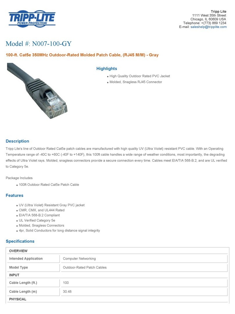
Tripp Lite
Tripp Lite N105-010-GY Specification sheet

Verizon
Verizon RFS HYBRIFLEX HBF058-08U1S1 Series installation instructions

Tripp Lite
Tripp Lite B055-001-SER quick start guide

Tripp Lite
Tripp Lite N201-014-BL Specification sheet

Tripp Lite
Tripp Lite N002-020-GY Specification sheet

Tripp Lite
Tripp Lite N304-008 Specification sheet

Tripp Lite
Tripp Lite N002-010-RD Specification sheet

Tripp Lite
Tripp Lite N302-08M Specification sheet

Tripp Lite
Tripp Lite N222-01K-GY Specification sheet

Tripp Lite
Tripp Lite N201-005-YW Specifications

Tripp Lite
Tripp Lite N201-014-BK Specification sheet

Tripp Lite
Tripp Lite N316-02M Specification sheet