Hobbes LANtest Pro 256652/LB User manual

This manual coversthe following models
256652/LB
256652/LBT
256652/IDT
256652/TK
256652/TFK
User Manual
Remote Network Cable Tester
TM
Pro
LANtest
LANtest Pro
LANtest Pro withtone generator
LANtest Pro withtone generator and4 remote IDs
LANtest Pro with256712A Probe
LANtest Pro with256712F Probe

Contents Page
1. Introduction 1
2. Features 1
3.
4.
.
.
5
. Product Profile 5
11. FaultStatus 8
. Battery Replacement
. Warning
LANtest Pro
LANtest Pro Specifications 2
LANtest Pro CableTest Operation 3
5 LANtest Pro Tone Generator Operation 3
6 LANtest Pro RemoteID Operation 4
7. Probe Features 4
8. Probe Specifications
9. Probe Operation 5
10
Introduction
Congratulations on yourpurchase of the LANtest Pro
network cable testerseries! The LANtest Pro is a small
hand-held cable tester, which enables network professionals
to quickly andeasily verify the integrity of Ethernettwisted
pair cables. Inone step, the LANtest Pro willtest twisted
pair cables foropen pairs, shorted pairs, reversed pairs,
crossed pairs andsplit pairs. Just push the TESTbutton, and
the LANtest Prowill automatically scanfor any existing
faults in yourcable. The specially designed remote
terminator is providedfor one-person testing of installed
cables. The tonegenerator function canbe used tosend a
signal through yourinstalled cables which can be tracedwith
the Probe orany cable tracer in the market.
Package Contents:
For 256652/IDT &256652/LBT Users can buy 256712A or
256712F to Upgradethe tone function
Item Number Remotes Manual Soft carrycase Probe Probewith filter
256652/LB
256652/LBT
1 Y Y N N
1 Y Y N N
4 Y Y N N
1 Y Y Y N
1 Y Y Y Y
256652/IDT
256652/TK
256652/TFK
LANtest Pro Features
Tests for wiring faults of open, short,reversed, crossed and
split pairs
Split pair faultdetection at aminimum 40cm cablelength
Testing of twisted pair cables to over450ft
Tone generator for tracing installed cables andlocating
faults (available onmodels 256652/LBT, 256652/TK,
256652/TFK and 256652/IDT)
Identification of upto 4 remote termination units (available
1
1
1
2
3
3
4
4
5
5
5
8
9
9

on model 256652/IDT)
Verificationof shield integrity
Cross talk detectionin excess of 3dB + 0.3dBat 3.5Mhz
between any twopairs
Specially designed remoteunit that enables one person to
test installed cables
Easy to readfault display and high speed testing
Debug mode fordetailed fault identification results
Auto sleep modeand power off switch todecrease power
consumption
LANtest Pro Specifications
Connectors
LANtest Pro MainUnit RJ45 jack
Remote Unit RJ45 jack
Pairs tested
1/2, 3/6, 4/5,7/8 and shield
LED display
Horizontal: 5 GreenLEDs for pair andshield display
(1-2, 3-6, 4-5,7-8 and shield)
TONE G. LED (for models 256652/LBT, 256652/TK,
256652/TFK and 256652/IDT)
Vertical: 5 Red LEDs for fault displayand #ID display
(OPEN, SHORT, REVERSED, MISWIRE,
SPLIT PAIRS and LOW BATTERY)
For 256652/IDT thefault display shares with the #ID
Display (#1, #2,#3, #4)
Cable test lengthlimit
Minimum: 0.4m Maximum:Over 200m
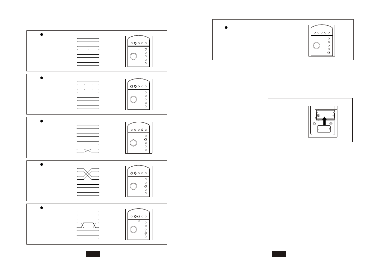
Power:
LANtest Pro: 6Valkaline DC battery
Remote identifier: Nobattery required
Dimensions:
LANtest Pro: 125x 52 x 30 mm (Lx W x H)
Low battery indicator
LANtest Pro Cable Test Operation:
1.Select "Cable" positionon the toggle switch.
2.Plug one endof the subject cable into theRJ45 jack on
the master unitand the other end into theRJ45 jack on
the remote terminator.
Note: The remote terminatorcan be slippedand locked intothe
master unit forconvenient testing ofpatch cables.
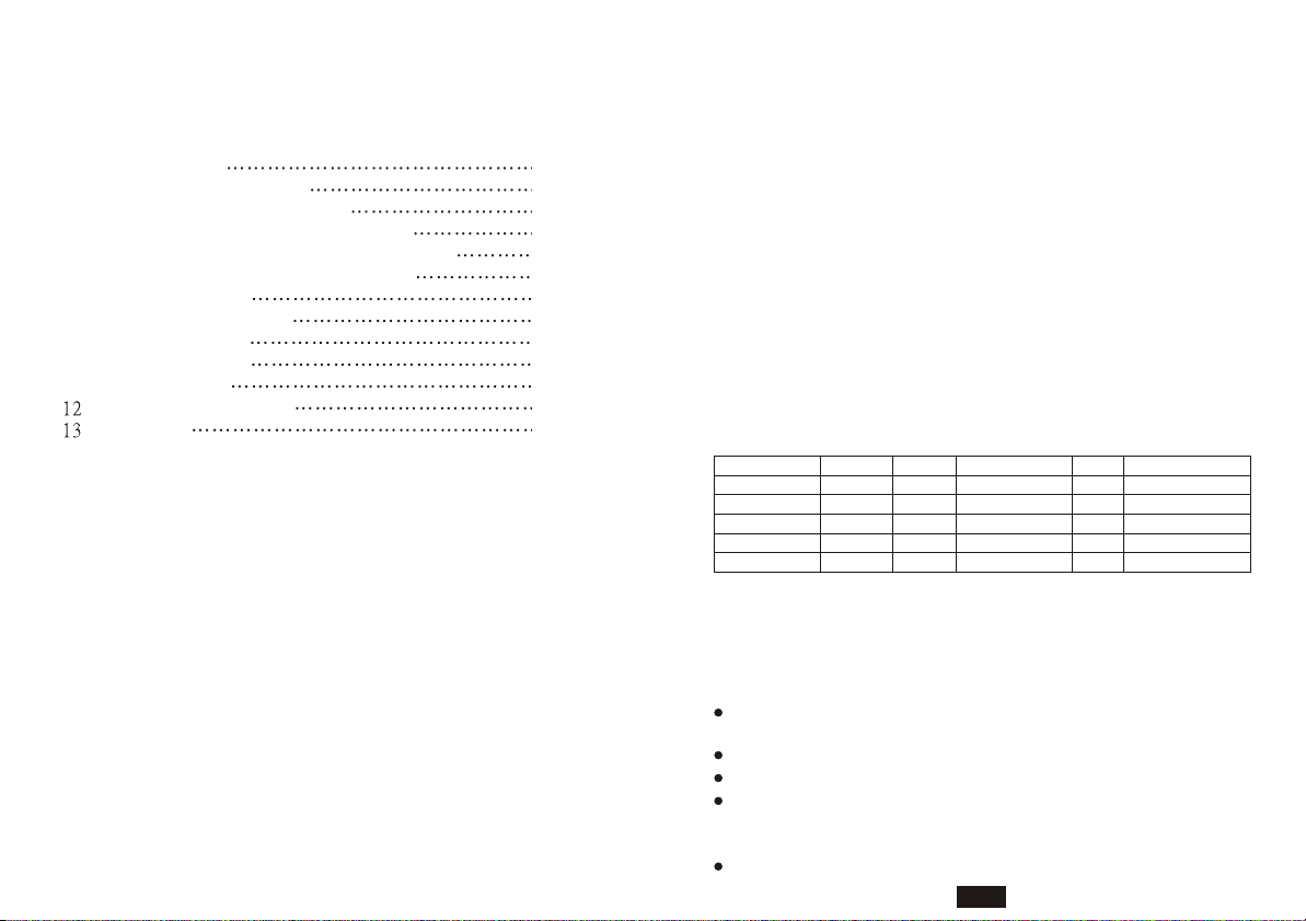
3.Push the testbutton and check the results: First,check
the 5 horizontallyaligned green LED indicators (1-2, 3-
6, 4-5, 7-8,SHIELD) for integrity status:
Solid light : pair is OK
Flashing light : pair is faulty
No light : open pair
a. Simultaneously, check the 5 vertically alignedLED
indicators (SHORT, REVERSED, MISWIRE,SPLIT
PAIRS)for the wiring faults.
b. For moredetailed information about what faults are
occurring in whichpairs, hold the TEST button for2
seconds to activate"Debug mode." The tester will test
each pair oneby one, pausing briefly on eachpair, and
display the correspondingfault status.
LANtest Pro Tone Generator Operation(only
available on models 256652/LBT, 256652/TK,
256652/TFK and 256652/IDT):
1. Slide thetoggle switch on the LANtest Proto the "Tone"
position
2. Quickly pressthe TEST button once for continuoustone
mode, or holddown for two full seconds forwarble tone
23

mode. To change modes,switch tester off and restart.
3. Using switchon side of Probe, select "speakermode,"
"LED mode" or"speaker & LED mode."
4. Use theProbe or any cable tracer totrace the subject
wire. Reception oftone will be loudest (amplifier) or
brightest (LED) onthe subject wire.
LANtest Pro Remote ID Operation (available on
model 256656/IDT)
1. Select "Cable"position on the toggle switch.
2. Plug oneend of the subject cable intothe RJ45 jack on
the master unitand the other end into theRJ45 jack on
the remote terminator.
3. Press theTEST button. One of the IDLED's will flash
three times. Thisindicates the numberof the remote
identification unit attachedto the farend of thesubject
cable. The testerwill then automaticallycontinue with
the same cabletest procedure as the standard LANtest
Pro.
Probe Features:
Special inductive plastictip which prevents accidental
shorts (possible withcopper-tip tracers) when using
near high voltagedevices
Traces and identifies wires orcable in a bundle or group
without damaging cableinsulation
Adjustable volume levelfor various work environments
Both amplifier andLED for loud or dark work
environments
Can work withany existing tone generator in themarket
Probe Specifications:
Pen-style casing
Special inductive plastictip
One push-button TRACEswitch
One battery lowLED indicator
One amplifier andone LED for signal detection
One rotary volumelevel switch
Probe Operation:
1. Withthe toggle switch on the side of the Probeunit,
select the modeof operation:
a. S & L: Speaker amplifier and LED tracing mode
b. Sp. : Speaker only tracingmode
c. L : LED only tracingmode
2. Press andhold the TRACE button while approaching
the subject cable. The intensity ofthe tone signal will
increase as theProbe approaches the cable.
Product Profile
2
14
12
3
LANtest
Remote Network Cable Tester
TM
Pro
16
15
9
13
LANtest
Remote Network Cable Tester
Pro
TM
REVERSED
SPLIT PAIRS
LOW BATTERY
TEST
MISWIRE
SHORT
11
10
1-2 3-6 4-5 7-8 SHIELD
6
8
7
45
1
4 5
256652/LB
1. Master port (RJ45)
2. Pair 1 indicator
3. Pair 2 indicator
4. Pair 3 indicator
5. Pair 4 indicator
6. Shield indicator
7. Short faults LED
8. Reversed faults LED
9. Miss wire faultsLED
10. Split pairs LED
11. Batterylow indicator
12. Testbutton
13. ON/OFF switch
14. Battery cover
15. Remote unit
16. Remote test port(RJ45)

256652/LBT (with tonegenerator model)
256652/IDT
LANtest Pro withtone generator and 4 remote IDs
2
14
17
12
3
LANtest
Remote Network Cable Tester
TM
Pro
16
15
9
13
LANtest
Remote Network Cable Tester
Pro
TM
REVERSED
SPLIT PAIRS
LOW BATTERY
TEST
4
MISWIRE
SHORT
2
3
1
11
10
1-2 3-6 4-5 7-8 SHIELD
TONE G. ID
6
8
7
45
1
15
13
3
3
12
19
18 20
14
Remote
Terminator
Remote
Terminator
4
Pro
TM
LOW BATTERY
LANtest
Remote Network Cable Tester
17
2
Remote
Terminator
2
16
Remote
Terminator
1
7
1
2
3
ID
TONE G.
TEST
1-2 3-6 4-5 7-8 SHIELD
SHORT
REVERSED
MISWIRE
4
SPLIT PAIRS 11
8
10
9
1
45
6
256652/TK
256652/LBT with 256712AProbe
256652/TFK
256652/LBT with 256712FProbe (with Filter)
Remote Network Cable Tester
LANtest
TM
Pro
12
14
4
17
2
ID
4
3
2
1
TEST
LOW BATTERY
TONE G.
MISWIRE
REVERSED
SHORT
SPLIT PAIRS
3
Pro
TM
LANtest
Remote Network Cable Tester
16 1-2 3-6 4-5 7-8 SHIELD
9
11
10
13
8
6
5
7
15 1
CABLE
TRACER
6
4
3
8
7
5
1
2
23
MISWIRE
14
TRACER
CABLE
TM
4
Pro
12
17
LOW BATTERY
SPLIT PAIRS
3
Remote Network Cable Tester
LANtest
11 13
LANtest
Remote Network Cable Tester 6
ID
1-2 3-6 4-5 7-8 SHIELD
2
TONE G.
SHORT
16
REVERSED
TEST
9
8
7
10
1
15
Pro
TM
45
1
8
3
4
67
1
25
NOISE FILTER
INCLUDED
6 7
1. Master port (RJ45)
2. Pair 1 indicator
3. Pair 2 indicator
4. Pair 3 indicator
5. Pair 4 indicator
6. Shield indicator
7. Short faults LED
8. Reversed faults LED
9. Miss wire faultsLED
10. Split pairs LED
11. Batterylow indicator
12. Test button
13. ON/OFF switch
14. Battery cover
15. Remote unit
16. Remote testport (RJ45)
17. Tone indicator
1. Master port (RJ45)
2. Pair 1 indicator
3. Pair 2 indicator
4. Pair 3 indicator
5. Pair 4 indicator
6. Shield indicator
7. Short faults LED
8. Reversed faults LED
9. Miss wire faultsLED
10. Split pairs LED
11. Batterylow indicator
12. Testbutton
13. Cable/Tonegenerator/OFF switch
14. Battery cover
15. Remote unit #1
16. Remote unit #2
17. Remote unit #3
18. Remote unit #4
19. Remote test port(RJ45)
20. Toneindicator
1. Master port (RJ45)
2. Pair 1 indicator
3. Pair 2 indicator
4. Pair 3 indicator
5. Pair 4 indicator
6. Shield indicator
7. Short faults LED
8. Reversed faults LED
9. Miss wire faultsLED
10. Split pairs LED
11. Batterylow indicator
12. Testbutton
13. ON/OFF switch
14. Battery cover
15. Remote unit
16. Remote test port(RJ45)
1. Inductive Plastic Tip
2. Visible Signal indicator
3. Low Battery
4. Trace button
5. Volume
6. Light /Speaker &Light/off switch
7. Speaker
8. Battery Cover

Fault Status
Short
Open
Reversed
Miss-wire
Split
TEST
SHORT
SPLIT PAIRS
LOW BATTERY
MISWIRE
REVERSED
1-2 3-6 4-5 7-8 SHIELD
6
3
2
1
6
3
1
2
5
8
7
4
5
7
8
4
55
7
8
7
8
3
4
6
2
1
3
4
6
2
1
1-2 3-6 4-5 7-8 SHIELD
TEST
SPLIT PAIRS
LOW BATTERY
SHORT
REVERSED
MISWIRE
TEST
SHORT
LOW BATTERY
MISWIRE
SPLIT PAIRS
REVERSED
1-2 3-6 4-5 7-8 SHIELD
6
3
4
5
8
7
6
3
4
5
7
8
2
11
2
5
7
8
3
6
4
5
7
8
6
4
3
1
2
1
2
TEST
SPLIT PAIRS
LOW BATTERY
SHORT
REVERSED
MISWIRE
1-2 3-6 4-5 7-8 SHIELD
8
TEST
SPLIT PAIRS
LOW BATTERY
SHORT
REVERSED
MISWIRE
1-2 3-6 4-5 7-8 SHIELD
5
7
8
3
6
4
5
7
8
6
4
3
1
2
1
2
1-2 3-6 4-5 7-8 SHIELD
TEST
LOW BATTERY
SPLIT PAIRS
SHORT
REVERSED
MISWIRE
Low Battery
Battery Replacement
When the LOWBATTERY light illuminates, the battery does
not have sufficient power to support an accuratetest. At this
time, you mustreplace it with a new battery.
Battery
Warning
1. Do notconnect LANtest Pro to a livecircuit as it may
damage the testerand interfere with a live network.
2. Testing in ahigh frequency activated area may cause the
tester to giveinaccurate readings.
3. Do notdrop or get the tester wetas it may cause internal
damage.
4. Do notplace the tester in areas ofhigh humidity or direct
sunlight.
5. Do notopen the tester or attempt torepair in case of
malfunction. Please sendit back to your distributor for
repair or replacement.
9
This manual suits for next models
4
Table of contents
Other Hobbes Network Cables manuals