ALLIANCE ELEVATOR JOURNEY LULA User manual

JOURNEY LULA Owner’s Manual
(Limited Use/Limited Application)
Sales | Service | Installation
80 Hill Avenue | Brantford, Ontario | N3R4H3 | 1.877.707 5004.


IMPORTANT
The Journey Commercial LULA Elevator must be installed, maintained and serviced by an
authorized CAMBRIDGE ELEVATING INC. dealer only. Under no circumstances is anyone
other than a trained and authorized Cambridge Elevating Inc. dealer to install, adjust,
service or modify any mechanical or electrical device on this elevator. As the owner, you
must be aware of your local elevator codes and ensuring periodic elevator maintenace.
Failure to follow this warning can result in safety systems being
compromised or defeated, which can result in serious injury or death.
Cambridge Elevating Inc. Inc. accepts no liability for property damage, warranty claims or
personal injury, including death, in this circumstance. Lift and elevator passenger safety is
the result of countless details in the equipment’s design, manufacture and installation. After
installation, reliable operation and continued assurance of safe operation requires regular
service and inspection to be carried out at an intervals determined by your local elevator
safetey code. Frequent usage and elevator environment may dictate increased service
and inspections. The owner is responsible to ensure that regular service and inspections
occur in a timely manner.
The owner must refer to this manual for operating instructions and precautions for usage of
this Commercial LULA Elevator.
On completion of installation, the dealer must provide the owner with the information
below and ensure it is recorded in the owner’s manual. Any service and/or maintenance
must also be recorded in the Maintenance Record section of this manual by the authorized
Cambridge Elevating Inc. dealer or the owner.
WARRANTY
Your Cambridge Elevating Inc. Dealer will provide a copy of the manufacturer’s limited
parts warranty and documentation relating to any labour warranty offered by your Dealer.
THIS PRODUCT IS DESIGNED AND MANUFACTURED TO EXACT SPECIFICATIONS. MODIFICATIONS
OF THIS PRODUCT IN ANY WAY CAN BE DANGEROUS AND WILL VOID THE WARRANTY.


TABLE OF CONTENTS
GENERAL SPECIFICATIONS Page 1
STANDARD FEATURES Page 1 - 4
OPERATING THE ELEVATOR FROM THE LANDING CONTROLS Page 5
OPERATING THE ELEVATOR FROM THE CAB CONTROLS Page 6
DOOR OPEN BUTTON Page 6
EMERGENCY BATTERY LOWERING Page 6
EMERGENCY LIGHT Page 7
EMERGENCY HANDS - FREE TELEPHONE (OPTIONAL) Page 7
MANUAL LOWERING DEVICE (MACHINE ROOM) Page 8
MAINTENANCE AND INSPECTION CHECKS Page 8


GENERAL SPECIFICATIONS
Load Capacity 1,400 lbs. (635 kg)
Rated Speed 30 feet per minute (0.15 m/s) (Nominal)
Power Supply 220 volt, 1PH, 30 amps | 208 volt, 3PH, 20 amps
Drive System 1:2 Cable Hydraulic
Cab Sizes: 42” Wide x 60” Deep | 48” Wide x 54” Deep | 51” Wide x 51” Deep | Custom
2 stops - 5 stops
Pit Depth Required 14” Minimum 96” Maximum
Overhead Clearance: 11’-6”
Control System Single Automatic Push Button
Floor Selection Magnetic Selector
Sub-Floor Material Plywood
Control Panel Finish Stainless Steel or Brass
Hall Station Finish Stainless Steel or Brass
Motor 5 HP (3.73 kW)
Cab Panel Finish Steel Cab with Plastic Laminate Finish
Lighting Supply 110 volt, 60 Hz, 15 amps
Door Opening 36” x 84” (915mm x 2150 mm) nominal
STANDARD FEATURES
Anti-Creep Re-leveling Device
Automatic Emergency Lighting
Automatic Timed Car Lighting
Digital Floor Indicator in Cab and Hall Stations
Emergency Lowering Valve at Pump
In Car Directional Indicators
Slack/broken Cable Safety Device
Stainless Steel Handrail
Tactile Plates
Upper, Lower and Final Limit Switches
1
STANDARD FEATURES
1) Phase 2 Fire Service Keyswitch (Optional)
The keyswitch in the ON position enables cab controls as per Code A17.1-2007 Section 2.27.
The keyswitch in the OFF position allows for normal lift operation. The keyswitch in the HOLD
position holds the doors open when the cab is at a landing.
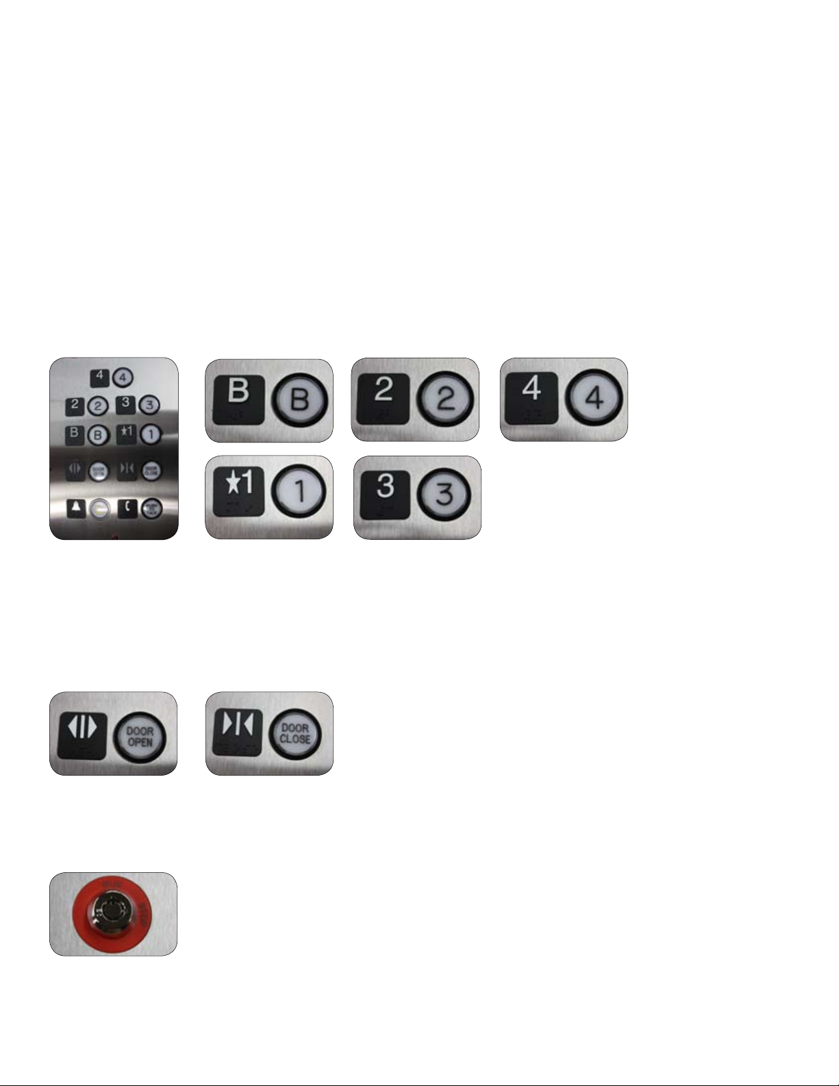
2) Cab Operating Panel (COP) Buttons
Once the selected landing button is pressed, the cab will automatically move to the
landing. The cab will stop when the selected landing is reached.
3) Door Open/Close Buttons
The elevator door will close automatically after a pre-set adjustable time
in seconds. This button can be pressed to open/close the door when the
cab is at a landing.
4) Emergency Stop Keyswitch
The keyswitch can be set to Stop at any time to stop the cab and activate the alarm buzzer.
2
STANDARD FEATURES
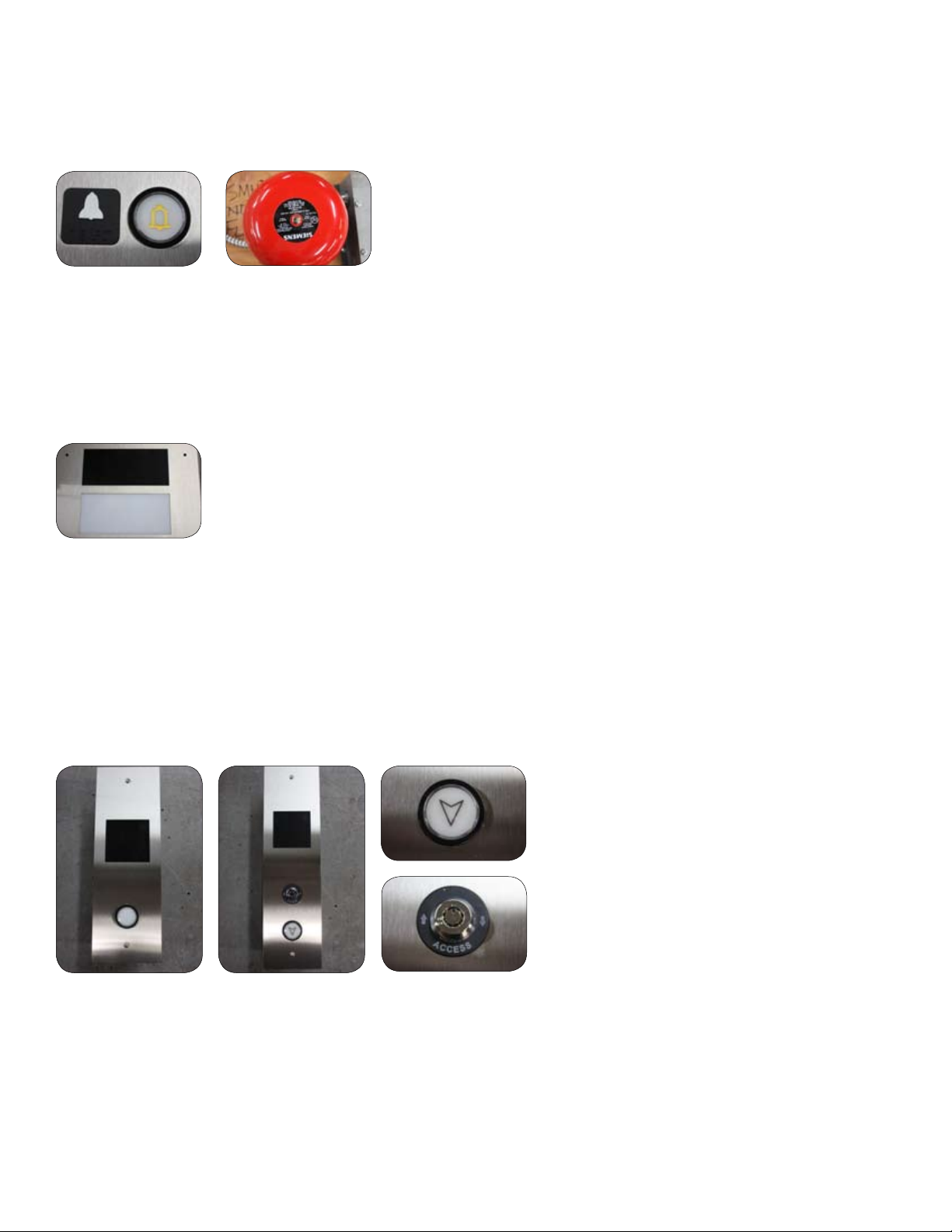
5) Alarm Button
The button can be pressed at any time to sound the alarm in case of an emergency.
6) Emergency Light | Digital Position Indicator
The COP emergency light remains ON to provide cab lighting in the event of a main power
failure. The emergency light uses an uninterupted power supply system with an automatic
recharger.
7) Landing Hall Call Station Controls
Hall Call Stations are installed at all landings to move the cab to the landing from which it is
being called. The position indicator displays the oor the cab is at. An optional keyswitch
limits the elevator’s use to authorized persons only. An optional Hoistway Access Hall Station
Keyswitch enables service hoistway access, used with the COP Hoistway Access Keyswitch.
8) Landing Door and/or Gate Interlock
The Landing Door/Gate lock prevents the movement of the cab unless the door/gate is in
the closed and locked position. If the door/gate is not completely closed, the cab will not
move.
3
STANDARD FEATURES
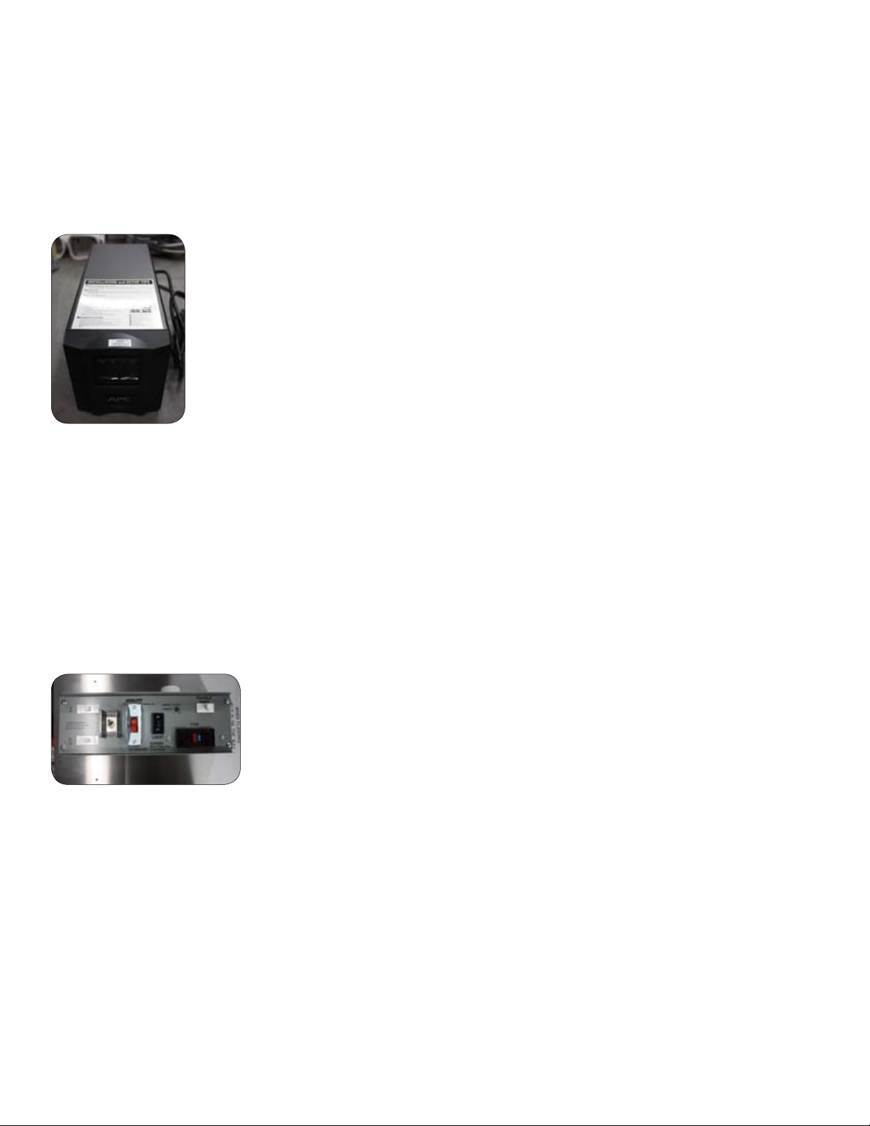
9) Emergency Battery Operation
In the event of a building power failure, the door/gate system is provided with an temporary
power back up system to continue the opening operation for a number of times. On resuming
normal building power, the back up system will turn OFF and begin automatic recharging.
10) Car Top Inspection Station (CTIS)
The CTIS is installed on all lifts and must be operated by qualied inspectors or Cambridge
Elevating Inc. dealer only. Set to NORMAL for normal lift operation, set to INSPECT with all
doors closed and locked for inspection purposes. Press and hold the ENABLE/SAFETY button,
then press and hold UP or DOWN button to run the cab in the selected direction. Set to the
red Stop Button RUN to allow the cab to run UP/DOWN during inspection, set to STOP to stop
the cab from running at any time.
11) Car Top Prop (When required by site conditions)
The Car Top Prop must be operated by qualied inspectors or Cambridge Elevating Inc.
dealers only. It is supplied when insufcient overhead hoistway clearance exists. Raise and
rotate the Prop counter-clockwise to the service position before operating the CTIS. Ensure
the Prop is stowed to normal position before the lift is returned to normal operation.
TO PREVENT SHEAR HAZARDS WHEN OPERATING THE CTIS, ALWAYS KEEP ALL BODY PARTS
INSIDE THE CAB ROOF EDGES AND AWAY FROM ANY HOISTWAY EXTRUSIONS. THE PIT PROP
MUST BE SET TO THE SERVICE POSITION (WHEN EQUIPPED).
4

OPERATING THE ELEVATOR FROM THE LANDING CONTROLS
To call Elevator to the Appropriate Level:
1) Press the CALL ELEVATOR button. The cab will automatically stop at your landing.
2) When the cab reaches the landing, the door lock on the landing door will automatically
release, then if the elevator is equipped with our Automatic 2-Speed Horizontal Sliding Doors
follow this procedure:
a) When the elevator reaches the landing, the sliding doors will open automatically. Enter
the cab and, after a few seconds, the doors will close behind you. Once inside the cab, lock
wheelchair wheels.
NOTE:
When using the landing controls, the cab can only be moved (called) to the level from which
you are calling. When using the control buttons in the cab, the cab can be moved to any
level.
WHEELCHAIR WHEELS MUST BE LOCKED AT ALL
TIMES WHEN THE ELEVATOR IS MOVING.
5

OPERATING THE ELEVATOR FROM THE CAB CONTROLS
1) If sitting in a wheelchair, set the brake on the wheelchair wheels or, if standing, hold on to
the handrail.
2) Press the appropriate oor button to “send” the cab to the desired landing.
3) When the cab reaches the landing, the door lock on the landing door will automatically
release, then: If the elevator is equipped with our Automatic 2-Speed Horizontal
Sliding Doors follow this procedure:
a) When the elevator reaches the landing, the door will “chime” and the sliding doors will
open automatically. Exit the cab and after a few seconds the doors will close behind you.
b) If cab is equipped with a gate, slide the gate open at this time and then open the manual
swing landing door. Exit the cab. Close the gate and then the landing door.
DOOR OPEN BUTTON
Located on the cab control panel of elevators equipped with 2-Speed Horizontal Sliding
Doors. The door open button has the following function:
When the elevator is at a landing level, the 2-Speed Horizontal Sliding Doors can be opened
by pressing the Door Open Button. Normally the doors will have opened and already closed
automatically when arriving at the landing. The Door Open Button allows the door to be
reopened.
EMERGENCY BATTERY LOWERING
This feature allows the lowering of the cab from inside the cab itself, without having to
get someone to manually lower it from inside the machine room. This device operates on
batteries and is only activated in the case of a main building power failure. The operation is
as follows:
1) Press any button below the oor where the elevator is located. The elevator will descend
and stop at the landing.
2) Upon arrival at the desired oor, the automatic doors (if equipped) will open. Exit the cab.
6

EMERGENCY LIGHT
In the event of a main power failure, the emergency cab light will light automatically.
EMERGENCY HANDS - FREE TELEPHONE
1) If your lift is equipped with an Emergency Hands-Free Telephone, press and hold down the
button in the telephone box to activate the phone line. A short time delay (adjustable by the
installing technician) will occur.
2) Release the button once the call is picked up by the telephone line. The system will
automatically dial out to a pre-programmed telephone number as set up by the installing
technician
MANUAL LOWERING DEVICE (MACHINE ROOM) (Figure 4)
TO BE DONE BY TRAINED PERSONAL ONLY!
In the event of power failure, the cab can be moved to a lower level manually by using the
following procedures:
1) Obtain the key to unlock the door to the machine room where the elevator pump unit is
located.
2) Instruct the person(s) in the elevator to remain calm and stay well back from the door of
the elevator. Ease their concern by telling them your intentions.
3) Switch the main disconnect switch to the “OFF” position for the main power supply to the
elevator pump unit.
4) Locate the red Manual Lowering Knob on the pump unit. Twist the Manual Lowering Knob
to lower the cab. See Figure 4. Maintain constant pressure on the knob until the elevator
reaches the lowest landing and stops automatically. (Although you may not be able to see
the elevator, this is readily
detected since there will be no further noise as the oil ows to the reservoir.)
7

MANUAL LOWERING DEVICE (MACHINE ROOM)
5) Obtain the special door release key and open the lower landing door. Assist the
passenger(s) from the cab.
6) After the passenger(s) have exited the cab, make sure hoistway door is closed, reconnect
disconnect switch inside the machine room and lock door behind you.
7) Return the key and special door release key to its original storage area.
UNDER NO CIRCUMSTANCES SHOULD THE PUMP
CONTROLS OR VALVE SETTINGS BE ADJUSTED
EXCEPT BY AN AUTHORIZED CAMBRIDGE ELEVATING INC.
DEALER.
8

MAINTENANCE AND INSPECTION CHECKS
Regular maintenance will keep your elevator in proper operating condition. Please
remember local elevator codes, as the owner of this elevator, you are responsible for making
sure that maintenance and upkeep are done on a regularly scheduled basis by licensed
technicians.
To ensure proper operating condition of your unit, the items listed below must be inspected
and, if necessary, serviced periodically as per local requirements. Additional inspections may
be required depending on usage.
1) Tighten all rail and cab fastening bolts.
2) Lubricate the door mechanism and adjust the door closure if required.
3) Inspect the travelling cable for wear. Replace if any cuts or damage to the jacket is
evident.
4) Check for any hose/pipe leaks. Replace and/or tighten the ttings to correct any
hydraulic leaks found.
5) Check the uid level of the pump reservoir (with the elevator at its lowest landing), and
ll as required. (Use Grade 32 Hydraulic Oil). There must be at least 1” (25 mm) of oil on the
dipstick.
6) Tighten any hose connections or bleeder valves found loose. Check the hydraulic cylinder
(jack) for any leaks. If necessary, the packing seals may have to be replaced.
7) Replace the batteries inside the control panel as indicated on the battery label.
8) Activate and test the safety mechanism.
9

Table of contents


