Alliance Steel AllianceLok 16 User manual
© Alliance Steel, Inc. 2015
THE NEW AND IMPROVED ALLIANCELOK 16
UNIVERSAL STANDING SEAM ROOF SYSTEM
INSTALLATION GUIDE
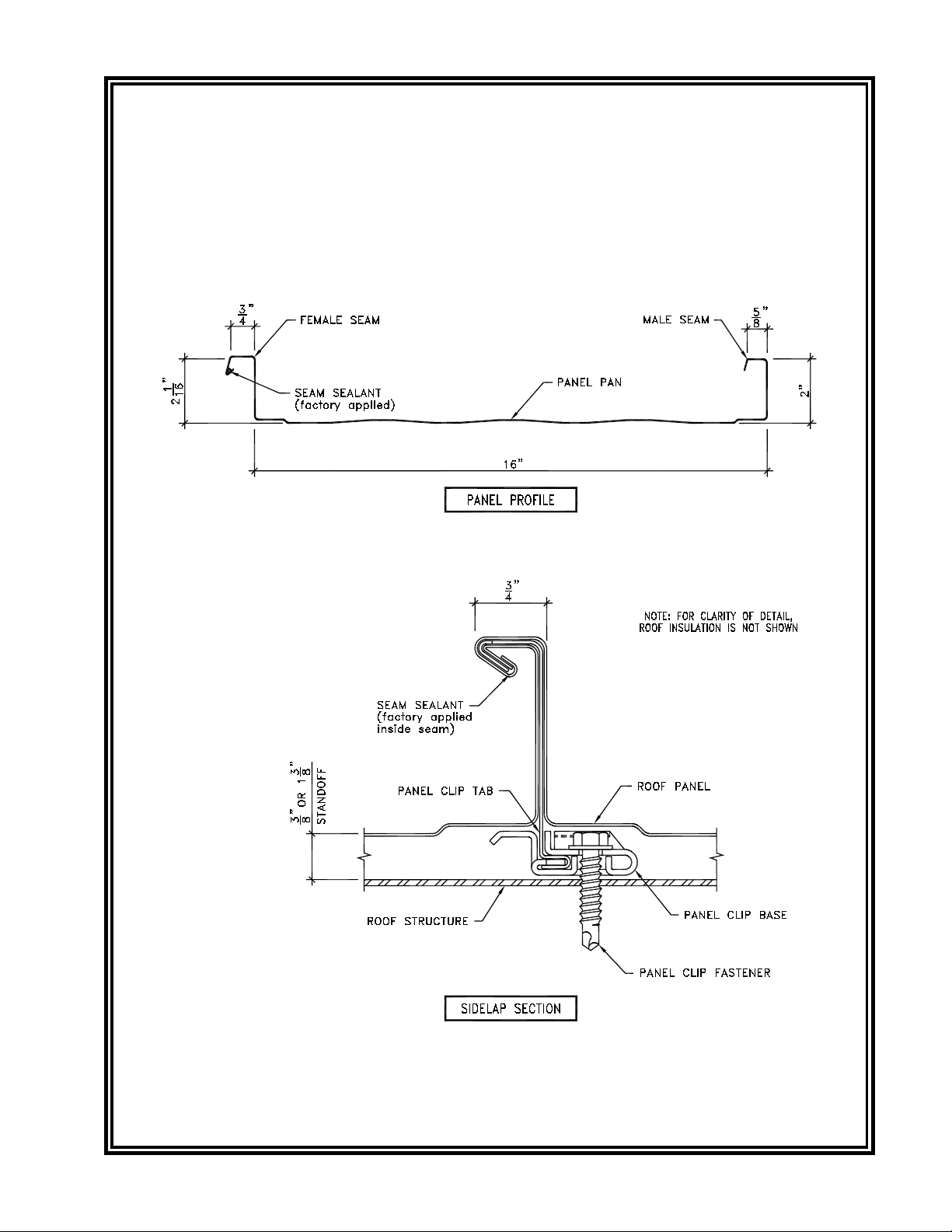
TripleLok™ Seam

Page 1
Dwg:
Date:
The New & Improved AllianceLok 16 Roof Systems Installation Guide
June 2015
INDEX
1.0 GENERAL
1.1 Purpose of the Installation Guide...................................................................................................... 2
1.2 Customer’s Responsibility ................................................................................................................ 2
2.0 SAFE ROOF INSTALLATION
2.1 Erector’s Responsibility .................................................................................................................... 3
2.2 OSHA................................................................................................................................................ 3
2.3 Walking & Working on Roof Panels .................................................................................................. 3
2.4 Handling Roof Materials in Strong Winds ......................................................................................... 4
3.0 CHECKING THE STRUCTURE
3.1 Completed and Braced ..................................................................................................................... 5
3.2 Lateral Stability ................................................................................................................................. 5
3.3 Alignment .......................................................................................................................................... 5
4.0 RECEIVING & HANDLING ROOF MATERIALS
4.1 Equipment for Unloading and Lifting................................................................................................. 6
4.2 Material Inventory ............................................................................................................................. 6
4.3 Lifting Roof Panel Bundles ............................................................................................................... 6
4.4 Field Storage of Roof Materials ........................................................................................................ 7
4.5 Handling Individual Roof Panels....................................................................................................... 8
5.0 ROOF INSTALLATION BASICS
5.1 Proper Tools..................................................................................................................................... 9
5.2 Equipment List .................................................................................................................................. 9
5.3 Sealants............................................................................................................................................ 9
5.4 Fasteners.......................................................................................................................................... 10
5.5 Field Cutting Panels and Flashing .................................................................................................... 11
6.0 ROOF PANEL LAYOUT
6.1 Sheeting Direction and Modularity.................................................................................................... 12
6.2 Layout & Checking for Coverage...................................................................................................... 12
6.3 Appearance Considerations.............................................................................................................. 12
7.0 INSPECTION OF ROOF ASSEMBLY DURING INSTALLATION
7.1 Importance of Inspection .................................................................................................................. 13
7.2 Inspection List................................................................................................................................... 13
8.0 STANDARD PARTS
8.1 General ............................................................................................................................................. 16
8.2 Standard Parts Details...................................................................................................................... 17
9.0 ROOF INSTALLATION DETAILS
9.1 General ............................................................................................................................................. 22
9.2 Preparation for Roof Panel Installation ............................................................................................. 23
9.3 Roof Panel Installation...................................................................................................................... 29
9.4 Termination Panel Installation........................................................................................................... 54
9.5 End Dam Installation......................................................................................................................... 62
9.6 Gable Trim Installation ...................................................................................................................... 70
9.7 Rake Transition Trim Installation....................................................................................................... 76
9.8 Ridge Cap Installation....................................................................................................................... 79
9.9 High Eave Transition Trim Installation .............................................................................................. 86
9.10 Eave Gutter Installation .................................................................................................................. 90
9.11 Hip and Valley Installation............................................................................................................... 94
The New & Improved AllianceLok 16 Roof Systems Seaming Guide............................................................ 97
The New & Improved AllianceLok 16 Roof Systems Architectural Details ................................................... 117
The New & Improved AllianceLok 16 Roof Systems Maintenance & Warranty Info .................................... 141
INDEX
Page 2
Dwg:
Date:
The New & Improved AllianceLok 16 Roof Systems Installation Guide
June 2015
1.0 GENERAL
1.1 Purpose of the Installation Guide
This Installation Guide is provided to Alliance Steel,
Inc. (“Alliance”) customers and their erectors as the
recommended procedure for the correct assembly of the
AllianceLok 16 Roof System.
This guide is intended to be used in conjunction with the
project’s Erection Drawings to help plan and organize
the installation of the AllianceLok 16 Roof System. The
Erection Drawings identify the applicable roof conditions
and govern specic part arrangements. This Installation
Guide will help you identify parts, establish the installation
sequence, demonstrate correct assembly, and point out any
areas or procedures requiring special emphasis or attention.
This Installation Guide applies to the standard AllianceLok
16 Roof System. Custom roof conditions, including custom
details and instructions, will be covered by the Erection
Drawings. In case of conict between this Installation
Guide and the Erection Drawings, the Erection
Drawings will have precedence.
1.2 Customer’s Responsibility
The customer is responsible for proper installation of the
roof in accordance with the Erection Drawings and this
Installation Guide, and in accordance with good engineering
and construction practices.
The customer must take the responsibility for selecting
a competent erector, insist that the work be performed
by qualied and experienced standing seam metal roof
installers, insist that the erector take time to study and
understand this guide, then assure that the erector correctly
follows the guide’s instructions.
Alliance does not guarantee and is not liable for the quality
of erection. Alliance is not responsible for building defects
that may be attributed to improper erection or the negligence
of other parties.
Clarification concerning the AllianceLok 16 roof
installation should be directed to the Alliance Customer
Service Department.
Contact the Alliance ofce:
Alliance Steel, Inc.
3333 S. Council Road
Oklahoma City, OK 73179-4410
(405) 745-7500 or (800) 624-1579
GENERAL
1.3 Weather Tightness Warranty Requirements
(if applicable)
Depending upon the type of warranty, Alliance may
require the roof installer to be certied by the manufacturer.
Warranty requirements should be veried on contract with
Alliance.
Alliance must approve in writing all roof penetrations prior
to installation. This includes but is not limited to; Roof Curbs,
Vent Pipes, & Mechanical Equipment. Submittals should
be forwarded to Alliance for review.
It is the customers responsibility to coordinate warranty
inspections with the Alliance warranty department.
Any special applications with regards to the weather
tightness of this roof system should be brought to the
attention of the warranty department at Alliance.

Page 3
Dwg:
Date:
The New & Improved AllianceLok 16 Roof Systems Installation Guide
June 2015
2.0 SAFE ROOF INSTALLATION
2.1 Erector’s Responsibility
The erector of the roof system is responsible for the safe
execution of this Installation Guide. These instructions are
intended to describe the sequence and proper placement
of parts. They are not intended to prescribe comprehensive
safety procedures.
If the erector cannot safely assemble the roof in accordance
with these instructions, it is the responsibility of the erector
to stop the work and contact Alliance to determine alternate
assembly procedures.
2.2 OSHA
The Occupational Safety and Health Act (OSHA) has
promulgated many regulations applicable to the
installation of this or any other roof system. These
regulations, identied as Part 1926, Safety and Health
Regulations for Construction, are available from any
government bookstore. The objective of the OSHA
standards is to protect the worker from injury or illness.
These OSHA regulations should be recognized as job site
requirements and be fully complied with.
Failure to do so may result in substantial nes in the event
of an OSHA inspection. Safe installation practices may
be further dened and made mandatory by state or local
ordinances.
Maintaining good housekeeping on the jobsite is
recognized as being important to both OSHA compliance
and to successful job completion.
2.3 Walking & Working on Roof Panels
Do not walk on the last installed panel run, as the
unsecured edge could collapse under a person’s weight.
When installing clips or making endlap connections, etc.,
stand where the Roof Structural will support your weight.
An approved and safe walking platform should be used
in high trafc areas to prevent the Roof Panel from being
deformed, scratched, or scuffed.
A. PLACING PANELS ON THE STRUCTURE
Do not place bundles of panels on the Roof Structure
without rst verifying the structure will safely support the
concentrated weight of the panels and the weight of the
installation crew. Some Roof Structures may not be
designed to support the weight of a full panel bundle without
additional structure support.
B. WALKING ON ROOF PANELS
Do not use a Roof Panel as a working platform. An
unsecured panel could collapse under the weight of a
person standing between purlins or at the panel end.
C906.200
SAFE ROOF INSTALLATION
Assembled
Sidelap
(Typ.)
Leading Roof Panel
Unassembled
Sidelap
CAUTION — INCORRECT
DO NOT step on leading (unsecured) Roof Panel.
Assembled
Sidelap (Typ.)
Leading Roof Panel
Unassembled
Sidelap
CORRECT
Step ONLY on secured Roof Panels

Page 4
Dwg:
Date:
The New & Improved AllianceLok 16 Roof Systems Installation Guide
June 2015
2.0 SAFE ROOF INSTALLATION
2.3 Walking & Working on Roof Panels (Continued)
C. SAFETY EQUIPMENT
The use of safety equipment for the Roof Panel installation
is recommended at all times during the installation process.
However, when using lanyards, ensure that the clasp, belt
hooks and wire cables are covered in such a manner that
they will not scratch the panel surface if accidentally dragged
along the panel.
D. CREW SIZE
The length of the individual Roof Panels should be
considered when determining the crew size. It is
recommended that under normal conditions, there be
one person for every ten feet of panel length, plus one.
E. PANEL OVERHANG
Do not stand on the end of unsupported (cantilevered)
panels at the eave or ridge. Standing on the cantilever
portion may result in panel collapse.
F. POINT LOADS
When properly supported by the structurals, panels are
designed to support uniform loads, which are evenly
distributed over the panel surfaces. Point loads that occur
in small or concentrated areas, such as heavy equipment,
ladder or platform feet, etc., may cause panel deformation
or even panel collapse.
G. SLICK SURFACES
Panel surfaces and structural steel surfaces are hard,
smooth, and nonabsorbent, which causes these surfaces
to be very slick when wet or covered with snow or ice.
Even blowing sand or heavy dust can make these surfaces
difcult to walk on without slipping.
Unpainted panel surfaces are often coated with oil to
accommodate the panel-fabrication process. Although
designed to wash away or evaporate during normal weather,
the oil on new panels can be extremely slick, especially
during periods of light rain or dew.
Caution must be exercised to prevent slipping and falling
onto the roof surface or even sliding off the roof. Non-slip
footwear is a necessity and non-slip working platforms are
recommended.
H. ELECTRICAL CONDUCTANCE
Metal panels are excellent electrical conductors. A common
cause of injury is the contact of metal panels with power
lines during handling and installation. The location of all
power lines must be noted and, if possible, agged. The
installation process must be routed to avoid accidental
contact with all power lines and high voltage services and
equipment. All tools and power cords must be properly
insulated and grounded and the use of approved ground
fault circuit breakers is recommended.
I. FALSE SECURITY OF INSULATION
Blanket and board insulation blocks the installer’s view of
the ground below the roof. Serious injury can occur when
the installer gets a false sense of security because he
cannot see the ground and steps through the insulation.
J. SHARP EDGES
Some edges of panels and trim are razor sharp and can
cause severe cuts if proper protective hand gear is not
worn. Be careful not to injure others while moving panels
and trim.
2.4. Handling Roof Materials in Strong Winds
Do not attempt to move panels in strong winds. Wind
pressure can easily cause a man to lose balance and fall.
Strong wind uplift on a panel can lift the weight of the man
carrying the panel.
Loose, wind borne panels are very dangerous and can
cause severe injury and damage.
Secure stacks of panels with banding or tie-downs, so
wind will not blow the panels off the roof. Clamp individual
unsecured panels to the Roof Structurals. Clamp or block
panel bundles and accessory crates to prevent them from
sliding down the roof slope.
SAFE ROOF INSTALLATION
Table of contents
Popular Air Conditioner manuals by other brands

Fujitsu
Fujitsu ASYG 09 LLCA installation manual

York
York HVHC 07-12DS Installation & owner's manual

Carrier
Carrier Fan Coil 42B Installation, operation and maintenance manual

intensity
intensity IDUFCI60KC-3 installation manual

Frigidaire
Frigidaire FAC064K7A2 Factory parts catalog

Sanyo
Sanyo KS2432 instruction manual


Mitsubishi Electric
Mitsubishi Electric PUHZ-RP50VHA4 Service manual

Panasonic
Panasonic CS-S18HKQ Service manual

Panasonic
Panasonic CS-E15NKE3 operating instructions

Gree
Gree GWH18TC-K3DNA1B/I Service manual

Friedrich
Friedrich ZoneAire Compact P08SA owner's manual

Daikin
Daikin R32 Split Series installation manual