Allice Messtechnik R&S ZND User manual

R&S®ZND
Vector Network Analyzers
User Manual
1173955702
Version 61
(;×íÇ2)
www.allice.de
Allice Messtechnik GmbH

This manual describes the R&S®ZND (2 ports, 9 kHz to 4.5 GHz, unidirectional, N connectors), order no.
1328.5170K92 and its options.
Hardware Options
●R&S®ZND-B7 "High Output Power", order no. 1338.1578.02
●R&S®ZND-B10 "GPIB Interface", order no. 1328.5358.02
●R&S®ZN-B14 "Handler I/O", order no. 1316.2459.05
●R&S®ZN-B19 "Additional Removable Harddisc", order no. 1326.7760.02
●R&S®ZN-B19 "Additional Removable SSD", order no. 1338.1703.02
Software Options
●R&S®ZND-K1 "Frequency range extension to 8.5 GHz for unidirectional instrument", order no.
1328.5306.02
(not compatible with R&S®ZND-K5 and R&S®ZND-K8)
●R&S®ZND-K2 "Time Domain (TDR)", order no. 1328.5393.02
●R&S®ZND-K3 "Distance to Fault (DTF)", order no. 1328.5393.02
●R&S®ZND-K5 "Bidirectional measurements 9 kHz to 4.5 GHz", order no. 1328.5312.02
(not compatible with R&S®ZND-K1 and R&S®ZND-K6)
●R&S®ZND-K6 "Bidirectional measurements 9 kHz to 8.5 GHz", order no. 1328.5329.02
(requires R&S®ZND-K1; not compatible with R&S®ZND-K5 and R&S®ZND-K8)
●R&S®ZND-K8 "Frequency range extension to 8.5 GHz for bidirectional instrument", order no.
1328.5412.02
(requires R&S®ZND-K5; not compatible with R&S®ZND-K1 and R&S®ZND-K6)
●R&S®ZND-K7 "Extended Power Range", order no. 1328.5335.02
●R&S®ZND-K19 "1 mHz Frequency Resolution", order no. 1326.8089.02
●R&S®ZND-K210 "EAZY De-embedding (EZD) based on IEEE 370", order no. 1328.8670.02
●R&S®ZND-K220 "In-Situ De-embedding (ISD) that covers IEEE 370", order no. 1328.8686.02
●R&S®ZND-K230 "Smart Fixture De-embedding (SFD)", order no. 1328.8692.02
●R&S®ZND-K231 "Delta-L 4.0 PCB characterization", order no. 1328.8705.02
© 2022 Rohde & Schwarz GmbH & Co. KG
Muehldorfstr. 15, 81671 Muenchen, Germany
Phone: +49 89 41 29 - 0
Email: [email protected]
Internet: www.rohde-schwarz.com
Subject to change – data without tolerance limits is not binding.
R&S® is a registered trademark of Rohde & Schwarz GmbH & Co. KG.
Trade names are trademarks of the owners.
1173.9557.02 | Version 61 | R&S®ZND
Throughout this manual, R&S® is abbreviated as R&S.
www.allice.de
Allice Messtechnik GmbH

Contents
R&S®ZND
3User Manual 1173.9557.02 ─ 61
Contents
1 Safety and regulatory information......................................................13
1.1 Safety instructions......................................................................................................13
1.2 Warning messages in the documentation................................................................ 15
1.3 Korea certification class A......................................................................................... 16
2 Welcome to the R&S ZND....................................................................17
2.1 What's new in firmware version 3.40.........................................................................17
2.2 Documentation overview............................................................................................20
2.2.1 Getting started manual..................................................................................................21
2.2.2 User manual and help................................................................................................... 21
2.2.3 Service manual............................................................................................................. 21
2.2.4 Instrument security procedures.....................................................................................21
2.2.5 Printed safety instructions............................................................................................. 21
2.2.6 Data sheets and brochures........................................................................................... 22
2.2.7 Release notes and open source acknowledgment (OSA)............................................ 22
2.2.8 Application notes, application cards, white papers, etc.................................................22
3 Getting started......................................................................................23
3.1 Preparing for use........................................................................................................ 23
3.1.1 Lifting and carrying........................................................................................................23
3.1.2 Unpacking and checking............................................................................................... 23
3.1.3 Choosing the operating site.......................................................................................... 23
3.1.4 Setting up the product................................................................................................... 24
3.1.5 Considerations for test setup........................................................................................ 26
3.1.6 Connecting the analyzer to the AC supply.................................................................... 27
3.1.7 Switching the instrument on and off.............................................................................. 27
3.1.8 Standby and ready state............................................................................................... 28
3.1.9 Windows operating system........................................................................................... 28
3.1.10 Minimizing the VNA application.....................................................................................30
3.1.11 Connecting external accessories.................................................................................. 31
3.2 Instrument tour............................................................................................................33
3.2.1 Front panel.................................................................................................................... 33
3.2.2 Rear panel.....................................................................................................................39
www.allice.de
Allice Messtechnik GmbH

Contents
R&S®ZND
4User Manual 1173.9557.02 ─ 61
3.3 Operating the instrument........................................................................................... 40
3.3.1 Manual operation.......................................................................................................... 40
3.3.2 Control elements of the application window..................................................................45
3.3.3 Working with dialogs..................................................................................................... 51
3.3.4 Handling diagrams, traces, and markers...................................................................... 52
3.3.5 Entering data.................................................................................................................56
3.3.6 Scaling diagrams...........................................................................................................59
3.4 Performing measurements.........................................................................................65
3.4.1 Transmission S-parameter measurement..................................................................... 65
3.4.2 Reflection S-parameter measurement.......................................................................... 72
4 Concepts and features........................................................................ 74
4.1 Basic concepts............................................................................................................74
4.1.1 Global (persistent) settings........................................................................................... 74
4.1.2 Recall sets.....................................................................................................................75
4.1.3 Traces, channels and diagrams.................................................................................... 75
4.1.4 Sweep control............................................................................................................... 77
4.1.5 Data flow....................................................................................................................... 82
4.2 Screen elements..........................................................................................................86
4.2.1 Display elements of a diagram......................................................................................86
4.2.2 Dialogs.......................................................................................................................... 97
4.2.3 Trace formats.............................................................................................................. 100
4.3 Measurement results................................................................................................ 108
4.3.1 S-parameters.............................................................................................................. 109
4.3.2 Reference impedances................................................................................................110
4.3.3 Impedance parameters................................................................................................112
4.3.4 Admittance parameters............................................................................................... 116
4.3.5 Wave quantities and ratios.......................................................................................... 117
4.3.6 Unbalance-balance conversion...................................................................................120
4.3.7 Stability factors............................................................................................................125
4.3.8 Delay, aperture, electrical length.................................................................................126
4.4 Operations on traces................................................................................................ 127
4.4.1 Limit check.................................................................................................................. 127
4.4.2 Trace files....................................................................................................................134
www.allice.de
Allice Messtechnik GmbH

Contents
R&S®ZND
5User Manual 1173.9557.02 ─ 61
4.4.3 Memory-mapped trace data transfer...........................................................................143
4.5 Calibration................................................................................................................. 145
4.5.1 Calibration types......................................................................................................... 146
4.5.2 Calibration standards and calibration kits................................................................... 157
4.5.3 Calibration pool........................................................................................................... 163
4.5.4 Calibration labels.........................................................................................................163
4.5.5 Automatic calibration...................................................................................................164
4.5.6 Scalar power calibration..............................................................................................175
4.5.7 Parallel calibration of multiple channels...................................................................... 181
4.5.8 Joining calibrations......................................................................................................181
4.6 Offset parameters and de-/embedding................................................................... 182
4.6.1 Offset parameters........................................................................................................182
4.6.2 Embedding and deembedding.................................................................................... 188
4.7 Optional extensions and accessories.....................................................................200
4.7.1 Frequency range extension to 8.5 GHz for unidirectional R&S ZND.......................... 201
4.7.2 Bidirectional measurements 100 kHz to 4.5 GHz for R&S ZND................................. 201
4.7.3 Bidirectional measurements 100 kHz to 8.5 GHz for R&S ZND................................. 201
4.7.4 Frequency range extension to 8.5 GHz for bidirectional R&S ZND............................ 201
4.7.5 Time domain analysis..................................................................................................202
4.7.6 Distance-to-fault measurements................................................................................. 209
4.7.7 Frequency resolution 1 mHz........................................................................................211
4.7.8 Eazy de-embedding based on IEEE 370.....................................................................211
4.7.9 In-situ de-embedding.................................................................................................. 213
4.7.10 Smart fixture de-embedding........................................................................................213
4.7.11 Delta-L 4.0 PCB characterization................................................................................214
4.7.12 Health and usage monitoring service (HUMS)............................................................215
4.7.13 High output power for R&S ZND................................................................................. 216
4.7.14 GPIB interface.............................................................................................................216
4.7.15 Handler I/O (universal interface)................................................................................. 216
4.7.16 Additional removable system drive............................................................................. 217
4.7.17 Extended power range................................................................................................ 217
4.7.18 USB-to-IEC/IEEE adapter........................................................................................... 217
4.7.19 External power meters................................................................................................ 218
www.allice.de
Allice Messtechnik GmbH

Contents
R&S®ZND
6User Manual 1173.9557.02 ─ 61
4.7.20 External switch matrices............................................................................................. 220
4.7.21 External DLLs..............................................................................................................226
4.7.22 R&S ZNXSIM.............................................................................................................. 228
5 GUI reference......................................................................................232
5.1 Function Keys and Softtools................................................................................... 232
5.2 Meas softtool............................................................................................................. 234
5.2.1 S-Params tab.............................................................................................................. 235
5.2.2 Ratios tab.................................................................................................................... 244
5.2.3 Wave tab..................................................................................................................... 247
5.2.4 Z←Sij tab.................................................................................................................... 250
5.2.5 Y←Sij tab.................................................................................................................... 252
5.2.6 Y-Z-Params tab........................................................................................................... 254
5.2.7 Imbal. CMRR tab.........................................................................................................256
5.2.8 Stability tab..................................................................................................................259
5.2.9 Power Sensor tab........................................................................................................260
5.2.10 External DLL tab......................................................................................................... 261
5.3 Format softtool..........................................................................................................265
5.4 Scale softtool.............................................................................................................271
5.4.1 Scale Values tab..........................................................................................................271
5.4.2 Scale Coupling tab...................................................................................................... 274
5.4.3 Zoom tab..................................................................................................................... 274
5.5 Trace Config softtool................................................................................................ 276
5.5.1 Traces tab................................................................................................................... 276
5.5.2 Mem tab...................................................................................................................... 281
5.5.3 All Mem All Data tab....................................................................................................284
5.5.4 Math tab...................................................................................................................... 285
5.5.5 Time Domain tab......................................................................................................... 291
5.5.6 Time Gate tab..............................................................................................................296
5.5.7 Distance to Fault tab................................................................................................... 298
5.5.8 Trace Statistics tab......................................................................................................298
5.5.9 Smooth Shift Hold tab................................................................................................. 304
5.5.10 Infinite Averaging tab...................................................................................................307
5.5.11 Trace Data tab.............................................................................................................308
www.allice.de
Allice Messtechnik GmbH

Contents
R&S®ZND
7User Manual 1173.9557.02 ─ 61
5.6 Lines softtool.............................................................................................................316
5.6.1 Limit Test tab...............................................................................................................316
5.6.2 Ripple Test tab............................................................................................................ 325
5.6.3 Circle Test tab............................................................................................................. 329
5.6.4 Display Circle tab........................................................................................................ 333
5.6.5 Horiz. Line tab............................................................................................................. 334
5.7 Marker softtool.......................................................................................................... 335
5.7.1 Markers tab................................................................................................................. 335
5.7.2 Marker Props tab.........................................................................................................338
5.7.3 Marker Search tab.......................................................................................................340
5.7.4 Multiple Peak tab.........................................................................................................345
5.7.5 Target Search tab........................................................................................................347
5.7.6 Bandfilter tab............................................................................................................... 349
5.7.7 Set by Marker tab........................................................................................................353
5.7.8 Info Field tab............................................................................................................... 355
5.7.9 Marker Coupling tab....................................................................................................355
5.8 Stimulus softtool.......................................................................................................357
5.8.1 Stimulus tab................................................................................................................ 357
5.8.2 Power tab.................................................................................................................... 359
5.8.3 Time Domain X-Axis tab..............................................................................................359
5.9 Power Bw Avg softtool............................................................................................. 361
5.9.1 Power tab.................................................................................................................... 361
5.9.2 Bandwidth tab............................................................................................................. 361
5.9.3 Average tab.................................................................................................................362
5.10 Sweep Softtool.......................................................................................................... 364
5.10.1 Sweep Params tab......................................................................................................364
5.10.2 Sweep Type tab.......................................................................................................... 367
5.10.3 Trigger tab................................................................................................................... 377
5.10.4 Sweep Control tab.......................................................................................................382
5.11 Cal softtool................................................................................................................ 386
5.11.1 Start Cal tab................................................................................................................ 386
5.11.2 Cal Devices tab........................................................................................................... 413
5.11.3 Pwr Cal Settings tab....................................................................................................427
www.allice.de
Allice Messtechnik GmbH

Contents
R&S®ZND
8User Manual 1173.9557.02 ─ 61
5.11.4 Use Cal tab................................................................................................................. 434
5.12 Channel Config softtool............................................................................................439
5.12.1 Channels tab............................................................................................................... 440
5.12.2 Port Config tab............................................................................................................ 443
5.12.3 Mode tab..................................................................................................................... 448
5.12.4 Pwr Cal Settings tab....................................................................................................449
5.13 Offset Embed softtool...............................................................................................449
5.13.1 Offset Embed dock widget.......................................................................................... 449
5.13.2 Offset tab.....................................................................................................................459
5.13.3 One Way Loss tab.......................................................................................................465
5.13.4 Single Ended tab.........................................................................................................467
5.13.5 Fixture modeling dialog............................................................................................... 469
5.13.6 Port Sets tab............................................................................................................... 483
5.13.7 Balanced tab............................................................................................................... 486
5.13.8 Ground Loop tab......................................................................................................... 489
5.13.9 Differential Match tab.................................................................................................. 491
5.13.10 Config tab....................................................................................................................493
5.13.11 Delta-L tab...................................................................................................................494
5.14 File softtool................................................................................................................501
5.14.1 Recall sets tab.............................................................................................................502
5.14.2 Favorites tab............................................................................................................... 506
5.14.3 Print tab.......................................................................................................................507
5.14.4 Printer Setup dialog.....................................................................................................508
5.14.5 Trace Data tab.............................................................................................................509
5.14.6 More tab...................................................................................................................... 510
5.14.7 Configure Additional Simulation Data dialog............................................................... 511
5.15 Applic softtool........................................................................................................... 514
5.15.1 External Tools application........................................................................................... 514
5.15.2 Distance to Fault Application.......................................................................................516
5.16 Display softtool......................................................................................................... 524
5.16.1 Diagram tab.................................................................................................................524
5.16.2 Split tab....................................................................................................................... 527
5.16.3 Config tab....................................................................................................................530
www.allice.de
Allice Messtechnik GmbH

Contents
R&S®ZND
9User Manual 1173.9557.02 ─ 61
5.16.4 View Bar tab................................................................................................................537
5.16.5 Touchscreen tab..........................................................................................................538
5.17 Setup softtool............................................................................................................ 539
5.17.1 Setup tab.....................................................................................................................539
5.17.2 Freq. Ref. tab.............................................................................................................. 564
5.17.3 Remote Settings tab....................................................................................................565
5.17.4 External Devices tab................................................................................................... 568
5.17.5 External Ports tab........................................................................................................574
5.18 Help softtool.............................................................................................................. 584
5.19 Additional Function Keys.........................................................................................585
6 Remote control...................................................................................587
6.1 Introduction to remote control.................................................................................587
6.1.1 Starting a remote control session................................................................................588
6.1.2 GPIB Explorer............................................................................................................. 588
6.1.3 Switchover to remote control.......................................................................................590
6.1.4 Combining manual and remote control....................................................................... 593
6.2 Messages................................................................................................................... 594
6.2.1 Device messages (commands and device responses)...............................................594
6.2.2 SCPI command structure and syntax..........................................................................594
6.2.3 SCPI parameters.........................................................................................................598
6.3 Basic remote control concepts................................................................................600
6.3.1 Traces, channels, and diagram areas......................................................................... 600
6.3.2 Active traces in remote control....................................................................................601
6.3.3 Initiating measurements, speed considerations.......................................................... 602
6.3.4 Addressing traces and channels................................................................................. 603
6.4 Command processing.............................................................................................. 604
6.4.1 Input unit..................................................................................................................... 604
6.4.2 Command recognition................................................................................................. 605
6.4.3 Data base and instrument hardware........................................................................... 605
6.4.4 Status reporting system.............................................................................................. 606
6.4.5 Output unit...................................................................................................................606
6.4.6 Command sequence and command synchronization................................................. 606
6.5 Status reporting system........................................................................................... 608
www.allice.de
Allice Messtechnik GmbH

Contents
R&S®ZND
10User Manual 1173.9557.02 ─ 61
6.5.1 Overview of status registers........................................................................................609
6.5.2 Structure of a SCPI status register..............................................................................609
6.5.3 Contents of the status registers...................................................................................611
6.5.4 Application of the status reporting system.................................................................. 617
6.5.5 Reset values of the status reporting system............................................................... 620
7 Command reference.......................................................................... 622
7.1 Special terms and notation...................................................................................... 622
7.1.1 Upper- vs. lower-case................................................................................................. 623
7.1.2 Special characters.......................................................................................................623
7.1.3 Parameters..................................................................................................................623
7.1.4 Numeric suffixes..........................................................................................................623
7.2 Common commands.................................................................................................624
7.3 SCPI command reference.........................................................................................625
7.3.1 CALCulate commands................................................................................................ 626
7.3.2 CONFigure commands................................................................................................811
7.3.3 CONTrol commands....................................................................................................819
7.3.4 DIAGnostic commands............................................................................................... 828
7.3.5 DISPlay commands.....................................................................................................830
7.3.6 FORMat commands.................................................................................................... 856
7.3.7 HCOPy commands..................................................................................................... 857
7.3.8 INITiate commands..................................................................................................... 863
7.3.9 INSTrument commands.............................................................................................. 866
7.3.10 MEMory commands.................................................................................................... 867
7.3.11 MMEMory commands................................................................................................. 869
7.3.12 OUTPut commands.....................................................................................................906
7.3.13 PROGram commands................................................................................................. 911
7.3.14 [SENSe:] commands...................................................................................................914
7.3.15 SOURce commands................................................................................................. 1018
7.3.16 STATus commands................................................................................................... 1045
7.3.17 SYSTem commands..................................................................................................1048
7.3.18 TRACe commands....................................................................................................1090
7.3.19 TRIGger commands..................................................................................................1093
7.4 HUMS and service date commands.......................................................................1100
www.allice.de
Allice Messtechnik GmbH

Contents
R&S®ZND
11User Manual 1173.9557.02 ─ 61
7.4.1 SNMP/REST commands...........................................................................................1100
7.4.2 System information commands................................................................................. 1104
7.4.3 Device tags commands............................................................................................. 1114
7.4.4 Utilization commands.................................................................................................1115
7.4.5 Service date commands............................................................................................ 1118
7.5 R&S ZVR/ZVABT compatible commands.............................................................. 1120
8 Programming examples...................................................................1143
8.1 Basic tasks...............................................................................................................1143
8.1.1 Typical stages of a remote control program.............................................................. 1143
8.1.2 Channel, trace and diagram handling........................................................................1146
8.2 Condensed programming examples..................................................................... 1152
8.2.1 Path-independent remote control programs..............................................................1153
8.2.2 Trace and diagram handling......................................................................................1153
8.2.3 Using markers........................................................................................................... 1162
8.2.4 Data handling............................................................................................................ 1164
8.2.5 Calibration................................................................................................................. 1168
8.2.6 Fixture modeling........................................................................................................1175
9 Error messages and troubleshooting............................................ 1177
9.1 Errors during firmware operation.......................................................................... 1177
9.1.1 Asynchronous errors................................................................................................. 1178
9.1.2 Errors during measurement.......................................................................................1178
9.2 Errors during firmware installation/update...........................................................1179
9.3 Collecting information for technical support....................................................... 1180
9.4 Contacting customer support................................................................................ 1182
10 Transporting..................................................................................... 1183
11 Maintenance, storage and disposal................................................1184
11.1 Cleaning................................................................................................................... 1184
11.2 Storage..................................................................................................................... 1184
11.2.1 Disposal.....................................................................................................................1184
12 Annexes............................................................................................ 1185
12.1 Administrative tasks............................................................................................... 1185
12.1.1 Firmware installation..................................................................................................1185
www.allice.de
Allice Messtechnik GmbH

Contents
R&S®ZND
12User Manual 1173.9557.02 ─ 61
12.1.2 Remote operation in a LAN....................................................................................... 1186
12.2 System recovery......................................................................................................1190
12.3 Interfaces and connectors......................................................................................1190
12.3.1 Rear panel connectors.............................................................................................. 1190
12.3.2 LAN interface.............................................................................................................1192
12.3.3 GPIB interface........................................................................................................... 1193
12.3.4 Handler I/O (universal interface)................................................................................1196
12.4 Showroom mode..................................................................................................... 1204
12.5 ENA emulation commands.....................................................................................1204
Glossary: Frequently used terms...................................................1212
List of commands............................................................................ 1218
Index..................................................................................................1240
www.allice.de
Allice Messtechnik GmbH

Safety and regulatory information
R&S®ZND
13User Manual 1173.9557.02 ─ 61
1 Safety and regulatory information
The product documentation helps you use the product safely and efficiently. Follow the
instructions provided here and in the following chapters.
Intended use
The product is intended for the development, production and verification of electronic
components and devices in industrial, administrative, and laboratory environments.
Use the product only for its designated purpose. Observe the operating conditions and
performance limits stated in the data sheet.
Where do I find safety information?
Safety information is part of the product documentation. It warns you of potential dan-
gers and gives instructions on how to prevent personal injury or damage caused by
dangerous situations. Safety information is provided as follows:
●In Chapter 1.1, "Safety instructions", on page 13. The same information is provi-
ded in many languages as printed "Safety Instructions". The printed "Safety
Instructions" are delivered with the product.
●Throughout the documentation, safety instructions are provided when you need to
take care during setup or operation.
1.1 Safety instructions
Products from the Rohde & Schwarz group of companies are manufactured according
to the highest technical standards. To use the products safely, follow the instructions
provided here and in the product documentation. Keep the product documentation
nearby and offer it to other users.
Use the product only for its intended use and within its performance limits. Intended
use and limits are described in the product documentation such as the data sheet,
manuals and the printed "Safety Instructions". If you are unsure about the appropriate
use, contact Rohde & Schwarz customer service.
Using the product requires specialists or specially trained personnel. These users also
need sound knowledge of at least one of the languages in which the user interfaces
and the product documentation are available.
Never open the casing of the product. Only service personnel authorized by
Rohde & Schwarz are allowed to repair the product. If any part of the product is dam-
aged or broken, stop using the product. Contact Rohde & Schwarz customer service at
http://www.customersupport.rohde-schwarz.com.
Lifting and carrying the product
The maximum weight of the product is provided in the data sheet. To move the product
safely, you can use lifting or transporting equipment such as lift trucks and forklifts. Fol-
low the instructions provided by the equipment manufacturer.
Safety instructions
www.allice.de
Allice Messtechnik GmbH

Safety and regulatory information
R&S®ZND
14User Manual 1173.9557.02 ─ 61
Choosing the operating site
Only use the product indoors. The product casing is not waterproof. Water that enters
can electrically connect the casing with live parts, which can lead to electric shock,
serious personal injury or death if you touch the casing. If Rohde & Schwarz provides
accessories designed for your product, e.g. a carrying bag, you can use the product
outdoors.
Unless otherwise specified, you can operate the product up to an altitude of 2000 m
above sea level. The product is suitable for pollution degree 2 environments where
nonconductive contamination can occur. For more information on environmental condi-
tions such as ambient temperature and humidity, see the data sheet.
Setting up the product
Always place the product on a stable, flat and level surface with the bottom of the prod-
uct facing down. If the product is designed for different positions, secure the product so
that it cannot fall over.
If the product has foldable feet, always fold the feet completely in or out to ensure sta-
bility. The feet can collapse if they are not folded out completely or if the product is
moved without lifting it. The foldable feet are designed to carry the weight of the prod-
uct, but not an extra load.
If stacking is possible, keep in mind that a stack of products can fall over and cause
injury.
If you mount products in a rack, ensure that the rack has sufficient load capacity and
stability. Observe the specifications of the rack manufacturer. Always install the prod-
ucts from the bottom shelf to the top shelf so that the rack stands securely. Secure the
product so that it cannot fall off the rack.
Connecting to power
The product is an overvoltage category II product. Connect the product to a fixed
installation used to supply energy-consuming equipment such as household applian-
ces and similar loads. Keep in mind that electrically powered products have risks, such
as electric shock, fire, personal injury or even death.
Take the following measures for your safety:
●Before switching on the product, ensure that the voltage and frequency indicated
on the product match the available power source. If the power adapter does not
adjust automatically, set the correct value and check the rating of the fuse.
●Only use the power cable delivered with the product. It complies with country-spe-
cific safety requirements. Only insert the plug into an outlet with protective conduc-
tor terminal.
●Only use intact cables and route them carefully so that they cannot be damaged.
Check the power cables regularly to ensure that they are undamaged. Also ensure
that nobody can trip over loose cables.
●If the product needs an external power supply, use the power supply that is deliv-
ered with the product or that is recommended in the product documentation or a
power supply that conforms to the country-specific regulations.
Safety instructions
www.allice.de
Allice Messtechnik GmbH
Safety and regulatory information
R&S®ZND
15User Manual 1173.9557.02 ─ 61
●Only connect the product to a power source with a fuse protection of maximum
20 A.
●Ensure that you can disconnect the product from the power source at any time.
Pull the power plug to disconnect the product. The power plug must be easily
accessible. If the product is integrated into a system that does not meet these
requirements, provide an easily accessible circuit breaker at the system level.
Cleaning the product
Use a dry, lint-free cloth to clean the product. When cleaning, keep in mind that the
casing is not waterproof. Do not use liquid cleaning agents.
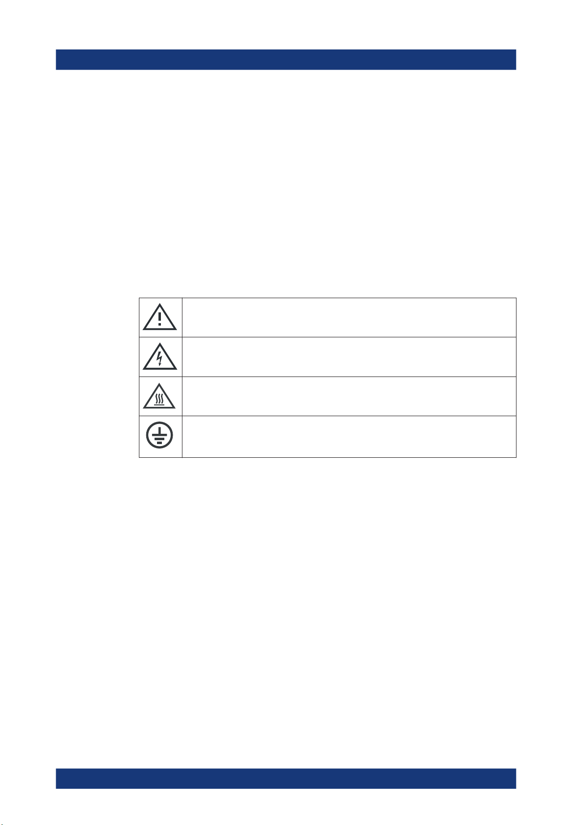
Meaning of safety labels
Safety labels on the product warn against potential hazards.
Potential hazard
Read the product documentation to avoid personal injury or product damage.
Electrical hazard
Indicates live parts. Risk of electric shock, fire, personal injury or even death.
Hot surface
Do not touch. Risk of skin burns. Risk of fire.
Protective conductor terminal
Connect this terminal to a grounded external conductor or to protective ground. This connec-
tion protects you against electric shock if an electric problem occurs.
1.2 Warning messages in the documentation
A warning message points out a risk or danger that you need to be aware of. The sig-
nal word indicates the severity of the safety hazard and how likely it will occur if you do
not follow the safety precautions.
WARNING
Potentially hazardous situation. Could result in death or serious injury if not avoided.
NOTICE
Potential risks of damage. Could result in damage to the supported product or to other
property.
Warning messages in the documentation
www.allice.de
Allice Messtechnik GmbH

Safety and regulatory information
R&S®ZND
16User Manual 1173.9557.02 ─ 61
1.3 Korea certification class A
이 기기는 업무용(A급) 전자파 적합기기로서 판매자 또는 사용자는 이 점을 주의하시기
바라며, 가정외의 지역에서 사용하는 것을 목적으로 합니다.
Korea certification class A
www.allice.de
Allice Messtechnik GmbH

Welcome to the R&S ZND
R&S®ZND
17User Manual 1173.9557.02 ─ 61
2 Welcome to the R&S ZND
This manual is intended to provide you with all information that is necessary for setup,
manual and remote control of the R&S ZND.
We also invite you to find out what's new in the current revision of the software and
learn how to make best use of our documentation and of the help system.
If you have any questions or comments, please contact your partners at Rohde &
Schwarz and give us your feedback.
2.1 What's new in firmware version 3.40
This manual describes version 3.40 of the R&S ZND firmware. Compared to the previ-
ous version 3.30, firmware version 3.40 provides the following changes:
New functionality
●Firmware support of Inline Calibration System R&S ZN-Z3x
See Chapter 4.5.5.4, "Inline calibration", on page 168
●Enhanced offline data analysis using R&S ZNXSIM:
– Channel-specific simulation data
– Channel-specific simulation data can be overwritten by port-specific S-parame-
ter data.
– Activate/deactivate "Simulation Noise" from the analyzer GUI
(deactivated per default)
See Chapter 4.7.22, "R&S ZNXSIM", on page 228
●Unidirectional R&S ZND now support automatic calibration (OSM at port 1, Trans
Norm and One Path Two Ports with source port 1).
●De-/embedding of virtual networks combined with scalar power calibration
See Chapter 5.11.3.3, "Power Meter Transmission Coefficients dialog",
on page 432
●User-definable print color scheme (independent of the user-definable display color
scheme)
See "Print Options" on page 509
●New "Operators Check" wizard that allows you to perform selftests and other help-
ful checks from one central place in the analyzer GUI
See Chapter 5.17.1.4, "Operators Check wizard", on page 559
Modified functionality
●Initially, or after a reset using CONTrol:HANDler:RESet, the Handler I/O gener-
ates active low signals (negative logic).
●The integrated license server was updated to version 2.0.1.1593.
●Wave quantity measurements: New renormalization (adapted from R&S ZNA)
yields different amplitudes and phases compared to previous renormalization
What's new in firmware version 3.40
www.allice.de
Allice Messtechnik GmbH

Welcome to the R&S ZND
R&S®ZND
18User Manual 1173.9557.02 ─ 61
New remote control features
●Deembedding tools ISD, SFD, and EZD:
– New commands CALCulate:FMODel:DIRectory, CALCulate:FMODel:
DIRectory:DEFault, and CALCulate:FMODel:DIRectory:DEFault:
CLEar for managing the common working directory
– New commands CALCulate:FMODel:ISD:IMPedance and CALCulate:
FMODel:SFD:IMPedance to set/get the global Use Impedance Correction
parameter of the respective deembedding tool
●New remote commands DISPlay:LAYout:OVERlay and DISPlay:LAYout:
SPLit for diagram functions Overlay All and Split All, respectively
Improvements
●Improved warning message in case you attempt to use an uncalibrated reference
receiver for source flatness calibration.
●Trace data export: The number of decimal places of stimulus and response values
can now be configured.
See "Decimal Places" on page 312
●Lower minimum "Ref Value" in polar diagrams allows larger scaling.
●In remote mode, a tap/click on the main window restores the "Remote" softtool.
●Distance to Fault measurements (R&S ZND-K3): Cable type attenuations can be
defined for frequencies > 6 GHz.
●For better accuracy, the "Compression Point" trace statistic is now calculated using
the a-wave (instead of the stimulus axis), if possible.
●New "Arbitrary Power" tab in "Port Settings" dialog gives access to power conver-
sion settings.
See "Arbitrary Power tab" on page 444.
●Marker values for wave and ratio traces in complex diagrams (polar coordinates)
●Optional display of X-axis grid labels in cartesian diagrams with linear scale.
See "Show X-Axis Grid Labels" on page 545
Solved issues
●Handler I/O PASS FAIL signal (pin 33)
– In immediate pass/fail mode (CONTrol:HANDler:PASSfail:MODE
NOWait), the PASS FAIL signal was only adjusted at the end of the sweep.
– The PASS FAIL signal showed the limit check of the current channel instead of
the global check result.
– In command CONTrol:HANDler:PASSfail:LOGic, the meaning of
POSitive and NEGative was inverted.
●A "Refl Norm Open" (REFL) calibration via remote control caused the firmware to
freeze, if the selected cal kit did not contain a Match standard.
●TRIGger:CHANnel<Ch>:AUXiliary:DURation <TrigOutDuration> did
not set the trigger output duration to the specified <TrigOutDuration>.
●Faulty dB conversion for "dB Mag Phase" markers and trace exports that use polar
coordinates (e.g. wave quantities or power sensor traces)
What's new in firmware version 3.40
www.allice.de
Allice Messtechnik GmbH

Welcome to the R&S ZND
R&S®ZND
19User Manual 1173.9557.02 ─ 61
●For time domain traces, CALCulate<Chn>:MARKer<Mk>:FUNC:DOMAIN:USER
commands did not accept values with units (and returned a misleading error mes-
sage).
●Markers on traces whose value at the marker position was above or below the visi-
ble range were not displayed.
●Option installation via GUI: Empty alert message if unsuccessful
●Bad zip compression performance of "Create R&S Support Information" could lead
to GUI freezes and Windows killing the VNA application.
●Automatic calibration:
– A previously defined calibration unit port assignment <Asg> ≥ 2 was not used
in
[SENSe<Ch>:]CORRection:COLLect:AUTO:ASSignment<Asg>:
ACQuire and hence led to bad calibration results.
– Changing the port assignment to non-default or after auto-detection did not
work and caused an exception.
– When performed via remote control, some automatic calibrations proceeded
without displaying calibration diagrams.
– If multiple automatic calibrations with port assignments have been prepared,
but have not been saved yet, then
[SENSe<Ch>:]CORRection:COLLect:AUTO:ASSignment:DELete:ALL
did not delete all port assignments. Subsequent port assignment definitions
failed.
●Communication via VXI-11 did not work after a firmware update from firmware ver-
sion < 3.0.
●SYSTem:ERRor:DISPlay:STATe OFF did not disable the display of information
popups.
●Marker format "dB Mag Phase": Incorrect magnitude calculation for certain trace
formats
●Time sweeps
– Inapplicable error popup "Sweep time exceeds requested time ..." for sweeps
with only one point
– Inconsistent timing for certain frequencies and IF bandwidths
●[SENSe<Ch>:]CORRection:COLLect:AUTO:ASSignment<Asg>:ACQuire
ignored the channel number and used the active channel instead.
●Some memory traces created using "Data & Func to New Mem" (or one of the cor-
responding parser commands) were not properly loaded from recall set.
●If the current length was zero, "Auto Length and Loss" always calculated a zero
loss.
●For some single-ended S-parameter measurements, "Cal Off" was displayed
although a calibration was applied.
●If a calibration unit was recharacterized with sexless connectors (e.g. 7 mm), sub-
sequent calibrations using this recharacterization failed with an "invalid cal unit
port" warning.
●DISPlay:LAYout HORizontal did the same as DISPlay:LAYout
VERTictal.
What's new in firmware version 3.40
www.allice.de
Allice Messtechnik GmbH

Welcome to the R&S ZND
R&S®ZND
20User Manual 1173.9557.02 ─ 61
●Switch matrix operation: if multiple matrix switch positions are needed, the external
"Channel (Sweep)" trigger required one trigger signal per matrix position instead of
one trigger signal per channel
●The channel base power Pb could not be increased above the maximum source
power PPmax of the R&S ZND, even though a port power offset PPoffset with
Pb + PPoffset ≤ PPmax
was set for all ports.
●R&S ZNXSIM with more than one R&S ZNPC smart card attached to the simula-
tion PC: The R&S ZND firmware simulation failed to start if it picked the "wrong"
smart card.
●Command CONFigure:CHANnel<Ch>[:STATe] ON did not make channel <Ch>
the active one.
●Touchstone file export: data for an export of 2 frequency points were exported in
reverse order
●Multiple peak marker search: once no peaks were found, the marker info field was
hidden permanently
●[SENSe<Ch>:]CDLL[:STATe] <DllName>, <Boolean> did not accept boo-
lean ON.
●µ1 and µ2 in "Stability" parameter selection combo-box erroneously prepended
with "Å"
●CALCulate<Ch>:DATA:CHANnel:ALL failed if, between measurement and data
retrieval, a lower-numbered channel was deleted.
●Mouse wheel scrolls in dialogs were propagated to the diagram area – with unde-
sired side effects such as changing the current marker position.
●Stability factor measurements always returned zero
●Opening the "System Config" dialog via the menu bar crashed the firmware.
●A recall set that was saved during an ongoing calibration could not be restored.
Firmware version
► To check your R&S ZND firmware version, select "Help" > "About..." from the main
menu.
2.2 Documentation overview
This section provides an overview of the R&S ZND user documentation. Unless speci-
fied otherwise, you find the documents on the R&S ZND product page at:
https://www.rohde-schwarz.com/manual/ZND
Documentation overview
www.allice.de
Allice Messtechnik GmbH
Table of contents
Other Allice Messtechnik Measuring Instrument manuals

Popular Measuring Instrument manuals by other brands


Rohde & Schwarz
Rohde & Schwarz FSMR26 Getting started

CARLO GAVAZZI
CARLO GAVAZZI WM4-96 - PROGRAMMING manual

Fluke
Fluke DTX-1800 Technical reference handbook

Hach
Hach TitraLab Basic user manual

Obvius
Obvius ModHopper R9120 Installation and operation manual

Thermo Scientific
Thermo Scientific Orion Star A111 reference guide