manuals.online logo
Brands
  1. Home
  2. •
  3. Brands
  4. •
  5. Allied Telesis
  6. •
  7. Switch
  8. •
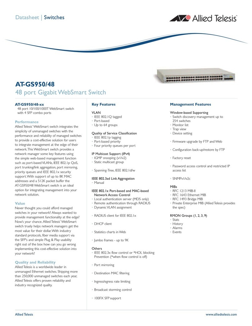
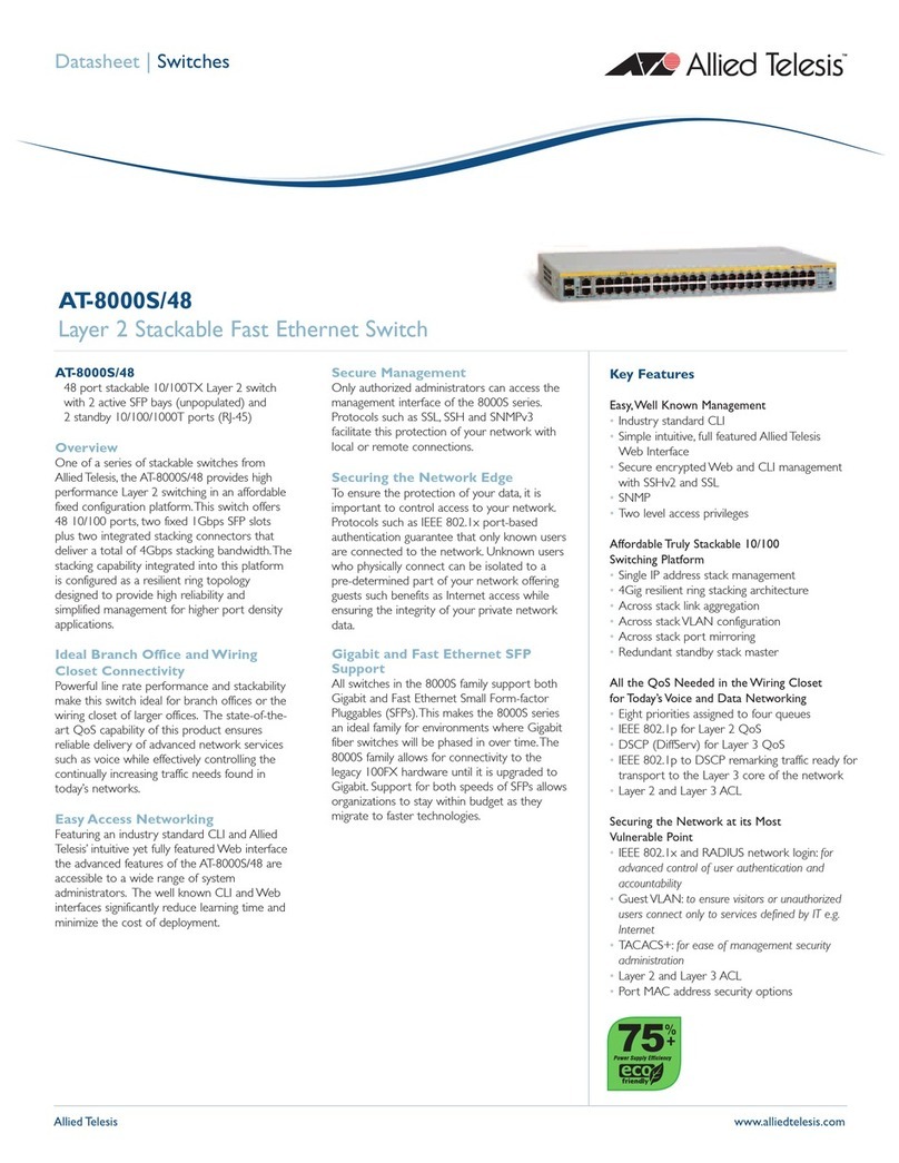
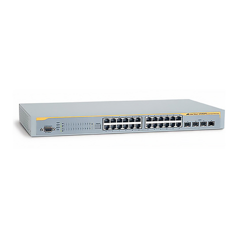
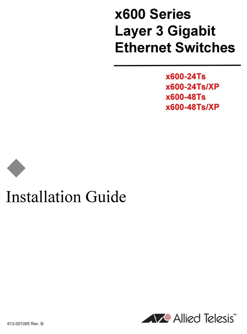
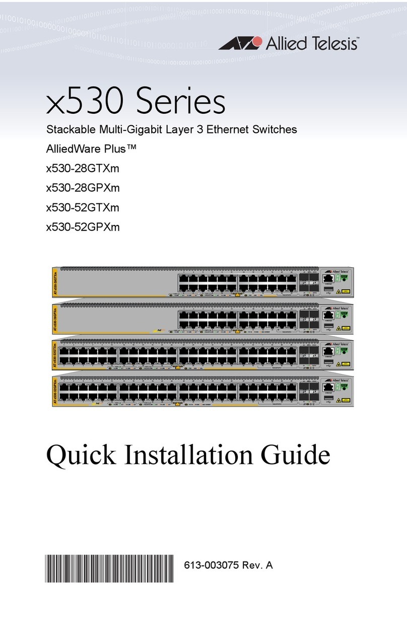
  9. Allied Telesis x950 Series User manual

Allied Telesis x950 Series User manual

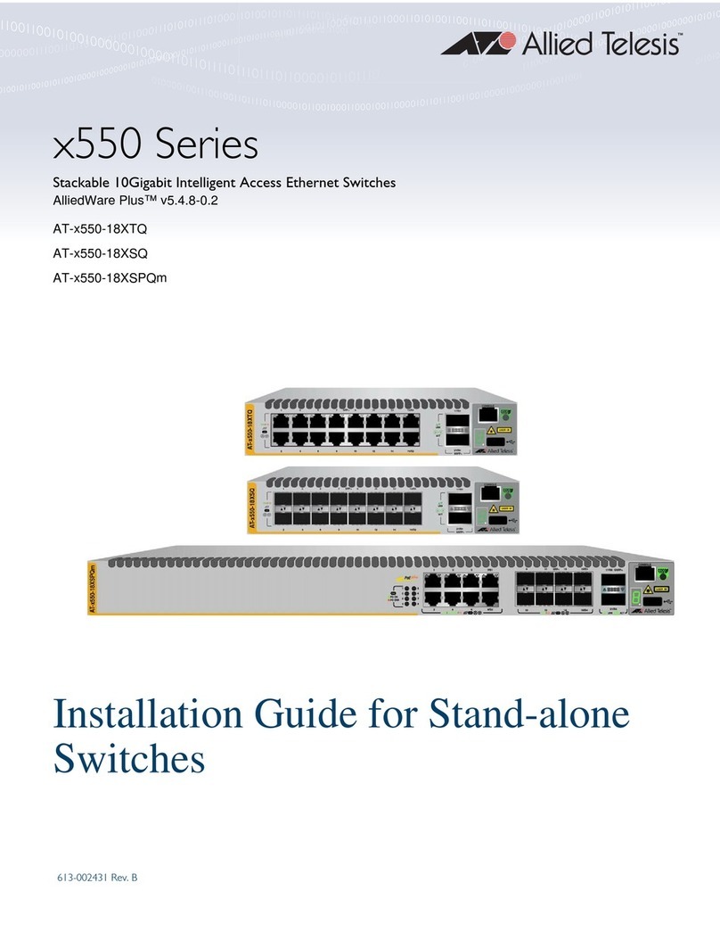
613-002642 Rev. D
x950 Series Switches
Advanced Layer 3+
AlliedWare Plus™ v5.5.0-1
x950-28XSQ Switch
x950-28XTQm Switch
x950-52XSQ Switch
XEM2-8XSTm Ethernet Line Card
XEM2-12XT Ethernet Line Card
XEM2-4QS Ethernet Line Card
XEM2-12XS Ethernet Line Card
XEM2-12XS v2 Ethernet Line Card
XEM2-4QS Ethernet Line Card
XEM2-1CQ Ethernet Line Card
PWR600 AC Power Supply
PWR600 DC Power Supply
FAN05 Fan Module
Installation Guide for Stand-alone
Switches
Copyright  2020 Allied Telesis, Inc.
All rights reserved. No part of this publication may be reproduced without prior written permission from Allied Telesis, Inc.
Allied Telesis, VCStack, and the Allied Telesis logo are trademarks of Allied Telesis, Incorporated. All other product names, company
names, logos or other designations mentioned herein are trademarks or registered trademarks of their respective owners.
Allied Telesis, Inc. reserves the right to make changes in specifications and other information contained in this document without prior
written notice. The information provided herein is subject to change without notice. In no event shall Allied Telesis, Inc. be liable for
any incidental, special, indirect, or consequential damages whatsoever, including but not limited to lost profits, arising out of or related
to this manual or the information contained herein, even if Allied Telesis, Inc. has been advised of, known, or should have known, the
possibility of such damages.
3
Electrical Safety and Emissions Standards
This product meets the following standards.
U.S. Federal Communications Commission
Radiated Energy
Note: This equipment has been tested and found to comply with the limits for a Class A digital device pursuant to Part 15
of FCC Rules. These limits are designed to provide reasonable protection against harmful interference when the
equipment is operated in a commercial environment. This equipment generates, uses, and can radiate radio frequency
energy and, if not installed and used in accordance with this instruction manual, may cause harmful interference to radio
communications. Operation of this equipment in a residential area is likely to cause harmful interference in which case
the user will be required to correct the interference at his own expense.
Note: Modifications or changes not expressly approved of by the manufacturer or the FCC, can void your right to operate
this equipment.
Industry Canada
This Class A digital apparatus complies with Canadian ICES-003.
Cet appareil numérique de la classe A est conforme à la norme NMB-003 du Canada.
Warning: In a domestic environment this product may cause radio interference in which case
the user may be required to take adequate measures.
EMI (Emissions) FCC Class A
CISPR 22 Class A
EN55032 Class A
VCCI Class A
ICES-003 Class A
RCM
EAC Certification
EMC (Immunity) EN 55024
EN 61000-3-2
EN 61000-3-3
Electrical Safety UL 60950-1 (CULUS)
EN 62368-1 (TUV)
EN 60825-1 (TUV)
Laser Safety EN 60825-1
RoHS RoHS6
4
Translated Safety Statements
Important: Safety statements that have the  symbol are translated into multiple languages in the
Translated Safety Statements document at www.alliedtelesis.com/support.
Remarque: Les consignes de sécurité portant le symbole  sont traduites dans plusieurs langues
dans le document Translated Safety Statements, disponible à l'adresse www.alliedtelesis.com/
library.
5
Preface................................................................................................................................................................................. 9
Document Conventions ................................................................................................................................................10
Contacting Allied Telesis ..............................................................................................................................................11
Chapter 1: Overview ........................................................................................................................................................ 13
x950 Switches ..............................................................................................................................................................14
Features .......................................................................................................................................................................16
Hardware Features ...............................................................................................................................................16
XEM2 Ethernet Line Cards ...................................................................................................................................16
Management Software and Interfaces ..................................................................................................................17
Management Methods ..........................................................................................................................................17
Management Panel ...............................................................................................................................................17
Power Supplies .....................................................................................................................................................18
Ports for 1/2.5/5/10Gbps SFP/SFP+ Transceivers.......................................................................................................19
SFP and SFP+ Transceivers.................................................................................................................................19
LEDs .....................................................................................................................................................................20
Ports for 1 to 24 on the x950-28XTQm Switch.............................................................................................................21
Cable Requirements .............................................................................................................................................21
LEDs .....................................................................................................................................................................22
Ports for 40Gbps QSFP+ or 100Gbps QSFP28 Transceivers, or Breakout Cables ....................................................23
QSFP28 Transceivers ...........................................................................................................................................23
QSFP+ Transceivers.............................................................................................................................................23
Breakout Cables....................................................................................................................................................23
LEDs .....................................................................................................................................................................24
Port Numbering for the x950-28XSQ and x950-28XTQm Switches......................................................................26
Port Numbering for the x950-52XSQ Switch.........................................................................................................27
Management Panel ......................................................................................................................................................28
USB Port ...............................................................................................................................................................29
NET MGMT Ethernet Management Port ...............................................................................................................29
Console (RS-232) Port ..........................................................................................................................................30
Switch ID LED .......................................................................................................................................................30
eco-friendly Button ................................................................................................................................................32
Optional Direct Attach Cables ......................................................................................................................................33
PWR600 AC and DC Power Supplies ..........................................................................................................................34
PWR600 AC Power Supply...................................................................................................................................35
LEDs .....................................................................................................................................................................35
PWR600 DC Power Supply ..................................................................................................................................37
LEDs .....................................................................................................................................................................37
FAN05 Cooling Fan......................................................................................................................................................39
Designating Ports in the Command Line Interface.......................................................................................................40
Examples for the PORT Parameter on Base Ports...............................................................................................41
Examples for the PORT Parameter on an XEM2 Line Card .................................................................................41
Software and Hardware Releases................................................................................................................................43
Chapter 2: XEM2 Ethernet Line Cards ........................................................................................................................... 45
Overview ......................................................................................................................................................................46
XEM2-8XSTm Line Card..............................................................................................................................................49
Twisted Pair Ports .................................................................................................................................................49
Twisted Pair Port LEDs .........................................................................................................................................50
Transceiver Ports ..................................................................................................................................................51
Contents
Contents
6
Transceiver Port LEDs ......................................................................................................................................... 51
XEM2-12XT Line Card ................................................................................................................................................ 53
Twisted Pair Ports ................................................................................................................................................ 53
LEDs..................................................................................................................................................................... 54
XEM2-12XTm Line Card.............................................................................................................................................. 55
Twisted Pair Ports ................................................................................................................................................ 55
LEDs..................................................................................................................................................................... 56
XEM2-12XS and XEM2-12XS v2 Line Cards.............................................................................................................. 57
Transceiver Ports ................................................................................................................................................. 57
Card Versions....................................................................................................................................................... 58
LEDs..................................................................................................................................................................... 58
XEM2-4QS Line Card.................................................................................................................................................. 60
Transceiver Ports ................................................................................................................................................. 60
LEDs..................................................................................................................................................................... 61
XEM2-1CQ Line Card.................................................................................................................................................. 62
Transceiver Port ................................................................................................................................................... 62
LEDs..................................................................................................................................................................... 62
Chapter 3: Beginning the Installation ............................................................................................................................ 65
Reviewing Safety Precautions ..................................................................................................................................... 66
Installation Options ...................................................................................................................................................... 71
Choosing a Site for the Chassis .................................................................................................................................. 72
Unpacking the Switch .................................................................................................................................................. 73
Verifying the Accessory Kit .......................................................................................................................................... 77
Unpacking the PWR600 AC Power Supply ................................................................................................................. 79
Unpacking the PWR600 DC Power Supply ................................................................................................................. 82
Chapter 4: Installing Power Supplies and Optional XEM2 Line Card ......................................................................... 83
Installing PWR600 AC Power Supplies ....................................................................................................................... 84
Installing PWR600 DC Power Supplies ....................................................................................................................... 88
Connecting the Grounding Wire .................................................................................................................................. 91
Connecting the DC Power Wires ................................................................................................................................. 94
Installing an Optional XEM2 Ethernet Line Card ......................................................................................................... 98
Chapter 5: Installing the Switch on a Table ................................................................................................................. 103
Chapter 6: Installing the Switch in an Equipment Rack ............................................................................................. 107
Beginning the Installation .......................................................................................................................................... 108
Required Items ................................................................................................................................................... 108
Switch Orientations in the Equipment Rack ....................................................................................................... 108
Removing the Bumper Feet....................................................................................................................................... 110
Installing the Switch................................................................................................................................................... 111
Chapter 7: Installing the Switch on a Wall ................................................................................................................... 115
Switch Orientations on a Wall.................................................................................................................................... 116
Recommended Minimum Wall Area Dimensions ...................................................................................................... 117
Plywood Base for a Wall with Wooden Studs............................................................................................................ 119
Installation Guidelines ............................................................................................................................................... 121
Tools and Material .............................................................................................................................................. 121
Installing the Plywood Base....................................................................................................................................... 123
Installing the Switch on the Plywood Base ................................................................................................................ 124
Installing the Switch on a Concrete Wall ................................................................................................................... 127
Chapter 8: Installing the Switch in the RKMT-SL01 Sliding Rack ............................................................................. 131
Introduction................................................................................................................................................................ 132
Rack Mount Kit Components ..................................................................................................................................... 133
Adjustable Outer Rails........................................................................................................................................ 133
Inner Rails .......................................................................................................................................................... 133
Extension Brackets............................................................................................................................................. 133
Equipment Rack Requirements ................................................................................................................................. 135
Reviewing Safety Precautions ................................................................................................................................... 136
Installation Overview ................................................................................................................................................. 139
Unpacking the Shipping Container ............................................................................................................................ 140
AT-x950-28XSQ Stand-alone Switch Installation Guide
7
Installing the Outer Rails on the Equipment Rack......................................................................................................142
Installing the Extension Brackets on the Inner Rails ..................................................................................................144
Measuring the Extension Bracket Lengths..........................................................................................................144
Assembling the Extension Brackets ....................................................................................................................146
Installing the Inner Rails on the Switch.......................................................................................................................150
Installing the Switch in the Equipment Rack...............................................................................................................152
Chapter 9: Verifying and Configuring the Switch ....................................................................................................... 155
Powering On the Switch .............................................................................................................................................156
Powering on the PWR600 AC Power Supply......................................................................................................156
Powering on the PWR600 DC Power Supply......................................................................................................158
Starting a Local Management Session.......................................................................................................................160
Verifying the Switch with AlliedWare Plus Commands...............................................................................................162
Disabling VCStack......................................................................................................................................................163
Configuring Ports for 40Gbps QSFP+ or 100Gbps QSFP28 Transceivers, or Breakout Cables ...............................166
Saving Your Changes and Rebooting the Switch.......................................................................................................168
Chapter 10: Cabling the Networking Ports .................................................................................................................. 169
Cabling Twisted Pair Ports .........................................................................................................................................170
Guidelines to Handling Twisted Pair or Fiber Optic Transceivers ..............................................................................171
Installing Transceivers................................................................................................................................................172
Installing Direct Attach Cables....................................................................................................................................179
Chapter 11: Replacing Modules ................................................................................................................................... 181
Replacing XEM2 Ethernet Line Cards........................................................................................................................182
Replacing PWR600 AC Power Supplies ....................................................................................................................187
Replacing PWR600 DC Power Supplies ....................................................................................................................192
Replacing FAN05 Modules.........................................................................................................................................195
Removing Fan Modules ......................................................................................................................................195
Installing Fan Modules ........................................................................................................................................197
Chapter 12: Troubleshooting ........................................................................................................................................ 201
Appendix A: Technical Specifications ......................................................................................................................... 207
Physical Specifications...............................................................................................................................................208
Environmental Specifications .....................................................................................................................................211
Power Specifications ..................................................................................................................................................212
Certifications...............................................................................................................................................................221
RJ-45 Twisted Pair Port Pinouts.................................................................................................................................222
RJ-45 Style Serial Console Port Pinouts ....................................................................................................................224
Contents
8
9
Preface
This guide contains the installation instructions for the x950 Series of
advanced Layer 3 Ethernet switches. The instructions explain how to
install the units as stand-alone switches. For instructions on how to build a
stack of switches with the VCStack feature, refer to the x950 Series
Installation Guide for Virtual Chassis Stacking.
This preface contains the following sections:
“Document Conventions” on page 10
“Contacting Allied Telesis” on page 11
Preface
10
Document Conventions
This document uses the following conventions:
Note
Notes provide additional information.
Caution
Cautions inform you that performing or omitting a specific action
may result in equipment damage or loss of data.
Warning
Warnings inform you that performing or omitting a specific action
may result in bodily injury.
x950 Series Installation Guide for Stand-alone Switches
11
Contacting Allied Telesis
If you need assistance with this product, you may contact Allied Telesis
technical support by going to the Support & Services section of the Allied
Telesis web site at www.alliedtelesis.com/support. You can find links for
the following services on this page:
24/7 Online Support — Enter our interactive support center to
search for answers to your product questions in our knowledge
database, to check support tickets, to learn about RMAs, and to
contact Allied Telesis technical experts.
USA and EMEA phone support — Select the phone number that
best fits your location and customer type.
Hardware warranty information — Learn about Allied Telesis
warranties and register your product online.
Replacement Services — Submit a Return Merchandise
Authorization (RMA) request via our interactive support center.
Documentation — View the most recent installation and user
guides, software release notes, white papers, and data sheets for
your products.
Software Downloads — Download the latest software releases for
your managed products.
For sales or corporate information, go to www.alliedtelesis.com/contact
and select your region.
Preface
12
13
Chapter 1
Overview
The chapter contains the following sections:
“x950 Switches” on page 14
“Features” on page 16
“Ports for 1/2.5/5/10Gbps SFP/SFP+ Transceivers” on page 19
“Ports for 1 to 24 on the x950-28XTQm Switch” on page 21
“Ports for 40Gbps QSFP+ or 100Gbps QSFP28 Transceivers, or
Breakout Cables” on page 23
“Management Panel” on page 28
“Optional Direct Attach Cables” on page 33
“PWR600 AC and DC Power Supplies” on page 34
“FAN05 Cooling Fan” on page 39
“Designating Ports in the Command Line Interface” on page 40
“Software and Hardware Releases” on page 43
Chapter 1: Overview
14
x950 Switches
The front panels of the switches are shown in Figure 1.
Figure 1. Front Panels of the x950 Switches
XEM2 Line Card
Expansion Slot
Ports 25, 29, 33, 37:
40Gbps or 100Gbps
Transceivers, or
10Gbps Breakout Cables
Management Panel
Ports 1 to 24:
1/2.5/5/10Gbps SFP/SFP+
Transceivers
x950-28XSQ Switch
XEM2 Line Card
Expansion Slot
Ports 25, 29, 33, 37:
40Gbps or 100Gbps
Transceivers, or
10Gbps Breakout Cables
Management Panel
Ports 1 to 24:
100Mbps, 1/2.5/5/10Gbps
Twisted Pair
x950-28XTQm Switch
Ports 49, 53, 57, 61:
40Gbps or 100Gbps Transceivers,
or 10Gbps Breakout Cables
Management Panel
Ports 1 to 48:
1/2.5/5/10Gps SFP/SFP+
Transceivers
x950-52XSQ Switch
x950 Series Installation Guide for Stand-alone Switches
15
The rear panel is shown in Figure 2.
Figure 2. Rear Panel of the x950 Switches
Two FAN05 Cooling Fan
Modules
Two Slots for PWR600
Power Supply Modules
Chapter 1: Overview
16
Features
The main hardware features of the x950 Switches are listed here.
Hardware
Features
The switch has the following hardware features:
1RU height
24 ports on the x950-28XSQ Switch for 1/2.5/5/10Gbps SFP/SFP+
transceivers. Refer to “Ports for 1/2.5/5/10Gbps SFP/SFP+
Transceivers” on page 19.
24 twisted pair ports on the x950-28XTQm Switch with speeds of
100Mbps and 1/2.5/5/10Gbps. Refer to “Ports for 1 to 24 on the
x950-28XTQm Switch” on page 21.
48 ports on the x950-52XSQ Switch for 1/2.5/5/10Gbps SFP/SFP+
transceivers. Refer to “Ports for 1/2.5/5/10Gbps SFP/SFP+
Transceivers” on page 19.
Four ports for 40Gbps QSFP+ or 100Gbps QSFP28 transceivers,
or 10Gbps breakout cables. Refer to “Ports for 40Gbps QSFP+ or
100Gbps QSFP28 Transceivers, or Breakout Cables” on page 23.
One expansion slot on the x950-28XSQ and x950-28XTQm
switches for an optional XEM2 Ethernet line card. Refer to Chapter
2, “XEM2 Ethernet Line Cards” on page 45.
The switches support two power supplies for primary and
redundant power. Refer to “PWR600 AC and DC Power Supplies”
on page 34.
The units comes with two pre-installed fan modules. Refer to
“FAN05 Cooling Fan” on page 39.
The switches come with brackets for standard 19-inch equipment
racks or wall installation.
The XEM2 Ethernet line cards, power supplies, and fan modules
are hot-swappable.
XEM2 Ethernet
Line Cards
The XEM2 Ethernet line cards are listed here:
The XEM2 Ethernet line cards are for the x950-28XSQ and
x950-28XTQm switches.
XEM2-8XSTm Card features four 100Mbps and 1/2.5/5/10Gbps
twisted pair ports with RJ-45 connectors and four ports for 1Gbps
SFP or 10Gbps SFP+ transceivers. Refer to “XEM2-8XSTm Line
Card” on page 49.
XEM2-12XT Card features 12 twisted pair ports with speeds of
100Mbps and 1/10Gbps, and RJ-45 connectors. Refer to
“XEM2-12XT Line Card” on page 53.
x950 Series Installation Guide for Stand-alone Switches
17
XEM2-12XTm Card features 12 twisted pair ports with speeds of
100Mbps and 1/2.5/5/10Gbps, and RJ-45 connectors. Refer to
“XEM2-12XTm Line Card” on page 55.
XEM2-12XS and XEM2-12XS v2 Cards feature 12 ports for
1/2.5/5/10Gbps SFP/SFP+ transceivers. Refer to “XEM2-12XS
and XEM2-12XS v2 Line Cards” on page 57.
XEM2-4QS Card features four ports for 40Gbps QSFP+
transceivers. Refer to “XEM2-4QS Line Card” on page 60.
XEM2-1CQ Card features one port for the 100Gbps QSFP28
transceiver. Refer to “XEM2-1CQ Line Card” on page 62.
Line cards are ordered separately. Refer to the product data sheet on the
Allied Telesis web site for a list of approved transceivers.
Management
Software and
Interfaces
Here are the management software and interfaces:
AlliedWare Plus management software.
Command line interface, available locally through the Console port
or remotely over the network.
Web browser interface available remotely over the network.
The AlliedWare Plus management software comes pre-installed on the
switch.
Management
Methods
You can manage the switch as follows:
Command line interface accessed locally through the Console port
or remotely using Telnet or Secure Shell.
Remote access using the web browser interface and HTTP.
Remote access with SNMPv1, v2c, or v3.
Management
Panel
The management panel has the following features:
Console RS-232 port for local management (no IP address
required),
USB 2.0 port for storing backup copies of system configuration
files, updating management software, and other management
functions.
An eco-friendly button for turning off the port and system LEDs to
reduce power consumption.
Note
The x950-52XSQ switch does not have the eco-friendly button.
Network management port for initial configuration and
maintenance access to the chassis.
Chapter 1: Overview
18
Power Supplies The switch has slots for two power supplies on the back panel. The switch
can be powered by a single power supply. Adding a second power supply
provides power redundancy. Power supplies are ordered separately.
Refer to “PWR600 AC and DC Power Supplies” on page 34.
x950 Series Installation Guide for Stand-alone Switches
19
Ports for 1/2.5/5/10Gbps SFP/SFP+ Transceivers
Ports 1 to 24 on the x950-28XSQ switch and ports 1 to 48 on the
x950-52XSQ switch support 1Gbps, 2.5Gbps, 5Gbps, and 10Gbps
SFP/SFP+ transceivers.
SFP and SFP+
Transceivers
Listed here are examples of 1Gbps SFP transceivers:
SPSX and LR short and long distance transceivers using
multi-mode or single mode fiber optic cable.
SPTX transceiver series with RJ-45 connector for twisted pair
cable.
SPEX transceivers with a maximum distance of two kilometers with
multi-mode fiber optic cable.
Listed here are examples of SFP+ 10Gbps transceivers:
SP10SR, LR, ER and ZR series of short or long distance
transceivers using multi-mode or single mode fiber optic cable.
SP10TW series of direct attach cables in lengths up to seven
meters.
SP10BD series of bidirectional transceivers for single mode fiber
optic cable with maximum distances of 10 to 40 kilometers
SP10T transceiver with RJ-45 connector for links up to 20 meters
at 10Gbps with Category 6a twisted pair cable, or 100 meters at
1Gbps.
SP10LRM Long Reach Multimode transceiver for OM1 multi-mode
fiber optic links up to 220 meters.
Note
Industrial (-40 to 85° C) and extended (-40 to 105° C) temperature
transceivers are available.
Here are transceiver guidelines:
The ports do not support 100Mbps-FX transceivers.
They support full-duplex mode only.
You can set the port speeds with Auto-Negotiation or manually.
The default is Auto-Negotiation.
Transceivers must be purchased separately. For a list of supported
transceivers, refer to the product data sheet on the Allied Telesis web site.
Chapter 1: Overview
20
LEDs The LEDs are located between the ports. Each port has one LED. Refer to
Figure 3.
Figure 3. Link and Activity LEDs for 1/2.5/5/10Gbps SFP/SFP+
Transceivers
The LEDs display link and activity status. The possible LED states are
described in Table 1.
Top Transceiver Port LED Bottom Transceiver Port LED
Table 1. Link and Activity Status LEDs for 1/2.5/5/10Gbps SFP/SFP+
Transceivers
State Description
Solid Green The transceiver has established a 2.5Gbps, 5Gbps,
or 10Gbps link to a network device.
Flashing Green The transceiver is transmitting or receiving data in
2.5Gbps, 5Gbps, or 10Gbps.
Solid Amber The transceiver has established a 1Gbps link to a
network device.
Flashing Amber The transceiver is transmitting or receiving data in
1Gbps.
Off Possible causes of this state are listed here:
- The transceiver slot is empty.
- The transceiver has not established a link to a
network device.
- The LEDs are turned off. To turn on the LEDs, use
the eco-friendly button.
Note
The x950-52XSQ switch does not have the
eco-friendly button.

Other manuals for x950 Series

2

This manual suits for next models

3

Other Allied Telesis Switch manuals

Allied Telesis x950-52XTQm User manual

Allied Telesis

Allied Telesis x950-52XTQm User manual

Allied Telesis AT 9924SP  AT-9924SP-30 AT-9924SP-30 Quick start guide

Allied Telesis

Allied Telesis AT 9924SP AT-9924SP-30 AT-9924SP-30 Quick start guide

Allied Telesis AT-8516F/SC Series User manual

Allied Telesis

Allied Telesis AT-8516F/SC Series User manual

Allied Telesis AT-GS950/16 User manual

Allied Telesis

Allied Telesis AT-GS950/16 User manual

Allied Telesis x900-12X Series User manual

Allied Telesis

Allied Telesis x900-12X Series User manual

Allied Telesis AT-9000/28 User manual

Allied Telesis

Allied Telesis AT-9000/28 User manual

Allied Telesis GS950 PS Series User manual

Allied Telesis

Allied Telesis GS950 PS Series User manual

Allied Telesis AT-8948 User manual

Allied Telesis

Allied Telesis AT-8948 User manual

Allied Telesis Rapier Series Instruction Manual

Allied Telesis

Allied Telesis Rapier Series Instruction Manual

Allied Telesis AT-FS704 User manual

Allied Telesis

Allied Telesis AT-FS704 User manual

Allied Telesis AT-GS900M Series User manual

Allied Telesis

Allied Telesis AT-GS900M Series User manual

Allied Telesis AT-9424Ts AC User manual

Allied Telesis

Allied Telesis AT-9424Ts AC User manual

Allied Telesis AT-GS950/8 User manual

Allied Telesis

Allied Telesis AT-GS950/8 User manual

Allied Telesis x600-24Ts-POE User manual

Allied Telesis

Allied Telesis x600-24Ts-POE User manual

Allied Telesis AT-8124XL User manual

Allied Telesis

Allied Telesis AT-8124XL User manual

Allied Telesis x510 Series User manual

Allied Telesis

Allied Telesis x510 Series User manual

Allied Telesis AT-8516F/SC Series User manual

Allied Telesis

Allied Telesis AT-8516F/SC Series User manual

Allied Telesis AT-FH708SW User manual

Allied Telesis

Allied Telesis AT-FH708SW User manual

Allied Telesis AT-GS924MX User manual

Allied Telesis

Allied Telesis AT-GS924MX User manual

Allied Telesis FS750 SERIES User manual

Allied Telesis

Allied Telesis FS750 SERIES User manual

Allied Telesis AT-8400 Series User manual

Allied Telesis

Allied Telesis AT-8400 Series User manual

Allied Telesis AT X900-12XT/S User manual

Allied Telesis

Allied Telesis AT X900-12XT/S User manual

Allied Telesis SwitchBlade AT-SB4108-00 Operating and maintenance manual

Allied Telesis

Allied Telesis SwitchBlade AT-SB4108-00 Operating and maintenance manual

Allied Telesis AT-GS916 User manual

Allied Telesis

Allied Telesis AT-GS916 User manual

Popular Switch manuals by other brands

Linksys EG005W - Instant Gigabit Workgroup Switch Brochure & specs

Linksys

Linksys EG005W - Instant Gigabit Workgroup Switch Brochure & specs

AMG AMG510-8G Series installation manual

AMG

AMG AMG510-8G Series installation manual

Acopia Adaptive Resource Switch Cli maintenance guide

Acopia

Acopia Adaptive Resource Switch Cli maintenance guide

ATEN AS-401PII user manual

ATEN

ATEN AS-401PII user manual

HP StorageWorks 2/16-EL Quickspecs

HP

HP StorageWorks 2/16-EL Quickspecs

D-Link DGS-1016T Specifications

D-Link

D-Link DGS-1016T Specifications

Extreme Networks Summit X150 Series Hardware installation guide

Extreme Networks

Extreme Networks Summit X150 Series Hardware installation guide

Siemens SIRIUS 3SE2903-1AE20 Original operating instructions

Siemens

Siemens SIRIUS 3SE2903-1AE20 Original operating instructions

ADTRAN NetVanta 1560-08-150W quick start

ADTRAN

ADTRAN NetVanta 1560-08-150W quick start

Cisco Catalyst 3560E-12SD Questions and answers

Cisco

Cisco Catalyst 3560E-12SD Questions and answers

Kramer VIA Collage quick start guide

Kramer

Kramer VIA Collage quick start guide

3Com CoreBuilder 9000 quick start guide

3Com

3Com CoreBuilder 9000 quick start guide

Transition Networks E-FX-HB-0800 user guide

Transition Networks

Transition Networks E-FX-HB-0800 user guide

Buffalo BS-GS2048 Quick setup guide

Buffalo

Buffalo BS-GS2048 Quick setup guide

MILBANK SYNAPSWITCH MATSCO10011 Owners & installation manual

MILBANK

MILBANK SYNAPSWITCH MATSCO10011 Owners & installation manual

Link electronics PAF-827 Specifications

Link electronics

Link electronics PAF-827 Specifications

3Com SuperStack 3 4900 SX Getting started guide

3Com

3Com SuperStack 3 4900 SX Getting started guide

Dungs LGW A2 Series instructions

Dungs

Dungs LGW A2 Series instructions

manuals.online logo
manuals.online logoBrands
  • About & Mission
  • Contact us
  • Privacy Policy
  • Terms and Conditions

Copyright 2025 Manuals.Online. All Rights Reserved.