Allmand Night-Lite V-Series User manual

Not for
Reproduction
en
Copyright © 2018 Allmand Bros., Inc.
Holdrege, NE, USA. All rights reserved.
Part No.: 114124USCN
Revision: A
Installation Instructions
Metal Halide to Conssin LED
Light Conversion Kit for
Night-Lite V-Series
es Instrucciones de instalación
Kit de conversión de haluro
metálico a luz LED Conssin
para serie Night-Lite V
fr Instructions d’installation
Trousse de conversion de
l’éclairage DEL Conssin à
halogénures métalliques pour
la série V Night-Lite

Not for
Reproduction
Model This Instruction Covers
If uncertain about any of the information in this instruction,
or if questions or problems arise, contact the Allmand
service department at 1-800-562-1373, or contact through
the Allmand website, www.allmand.com
• Night-Lite V-Series
Kit Contents
Allmand Parts & Service
Locate and identify the kit contents using the table below.
Ref Description Qty
1. 1/2-13 nyloc hex nut 4
2. 1/2-13 x 1-1/4 hex head bolt 4
3. 1/2 at washer 4
4. Conssin LED light 4
5. Conssin 4-LED drivers panel assembly 1
6. LED light CSA stop bracket 4
7. LED driver input cord 2
8. LED driver output cord 2
9. 2 wire lever locks 8
10. 8” cable tie 8
2 www.allmand.com
These kit instructions cover the conversion of metal halide
SHO lights to Conssin LED lights for Night-Lite V-Series.
Kit Instructions Description
1. Shut down the unit and allow ample time for engine
and lamps to cool. Refer to operator’s manual.
Before Kit Installation
DANGER
Electrocution Hazard
• Attempting to install the kit without rst shutting down
the unit will result in death or serious injury. Shut down
the unit before installing the kit.
WARNING
Burn Hazard
• Contact with hot surfaces of the engine and lamps
could result in death or serious injury. Always keep
clear of the engine, lamps and other hot areas of the
light tower.
2. Disconnect the battery, black negative (-) cable rst,
followed by red positive (+) cable. Refer to operator’s
manual.
DANGER
Electrocution Hazard
• Attempting to install the kit without disconnecting the
battery will result in death or serious injury. Disconnect
the battery before installing the kit.
Kit Installation: Subassembly
1. Conssin LED light subassembly. Steps for assembling
the LED light CSA stop bracket to the Conssin LED
light are as follows:
a. From the kit contents install the LED light CSA stop
bracket (A, Figure 1, Ref. 6) onto the Conssin LED
light yoke bracket (B, Figure 1, Ref. 4) using the 1/2-
13 nyloc hex nut, 1/2-13 x 1-1/4 hex head bolt, and
1/2 at washer (C, Figure 1, Ref. 1, 2, & 3).
b. Repeat step on another Conssin LED light. On the
other two repeat the same step, but on the opposite
side of the light yoke bracket.
2. Locate the Conssin 4-LED drivers panel assembly
(D,Figure 2a, Ref. 5) from the kit contents. The LED
drivers on the panel are numbered #1 through #4 as
shown in Figure 2a. Remove the hardware (E, Figure
2b) securing the LED driver junction box (F, Figure 2b)
to the LED driver panel. Set hardware aside as it will
be used in step 7. Open junction box.
1
AC
C
B

Not for
Reproduction
3
en
English
3
2b E
Output
Input 1 & 2
Input 3 & 4
F
3. LED Output driver cord subassembly. Steps for
assembling the LED driver output cord to the Conssin
4-LED drivers panel assembly are as follows:
a. Loosen the Output cord grip (G, Figure 3). From the
kit contents, run one end of the LED driver output
cord (H, Figure 3, Ref. 8) through the cord grip.
b. Locate the lever locks that are coming from the
outputs of the LED drivers. Connect the LED driver
output cord wires with the lever locks. Connect the
black wire (I, Figure 3) of the LED output cord to the
brown wire coming from LED driver #1. Connect the
white wire (J, Figure 3) to the blue wire coming from
LED driver #1. Connect the green wire (K, Figure
3) to the blue wire coming from LED driver #2.
Connect the red wire (L, Figure 3) to the brown wire
coming from LED driver #2. Connect the blue wire
(M, Figure 3) to the brown wire coming from LED
driver #3. Connect the orange wire (N, Figure 3) to
the blue wire coming from LED driver #3. Connect
the white with black stripe wire (O, Figure 3) to the
blue wire coming from LED driver #4. Connect the
red with black stripe wire (P, Figure 3) to the brown
wire coming from LED driver #4.
G
H
J
L
N
P
I
K
M
O
2a
Driver 2
D
Driver 4
Driver 1
Driver 3
Front of Driver Panel
Back of Driver Panel

Not for
Reproduction
www.allmand.com4
4
Q
R
T
S
V
U
5. LED Input 3 & 4 driver cord subassembly. Steps for
assembling the LED driver output cord to the Conssin
4-LED drivers panel assembly are as follows:
a. Loosen the Input 3 & 4 cord grip (W, Figure 5).
From the kit contents, run the cord end without ring
terminals of the remaining of the LED driver input
cord (X, Figure 5, Ref. 7) through the cord grip.
b. Locate the lever locks that are coming from the
inputs of the LED drivers. Connect the LED driver
input cord wires with the lever locks. Connect the
green wire (Y, Figure 5) of the LED Input cord to
the green with yellow stripe wire coming from LED
drivers #3 and #4. Connect the black wire (Z, Figure
5) to the brown wire coming from LED driver #3.
Connect the red wire (AA, Figure 5) to the brown
wire coming from LED driver #4. Connect the white
wire (BB, Figure 5) to the blue wire coming from
LED drivers #3 and #4.
6. Tighten up all the cord grips on the open junction box.
7. Close up the junction box on the back of the LED
drivers panel assembly. Be careful not to pinch any
of the wires. Use the hardware removed in Step 2 to
secure the junction box in place.
5
W
X
Y
Z
AA
BB
4. LED Input 1 & 2 driver cord subassembly. Steps for
assembling the LED driver output cord to the Conssin
4-LED drivers panel assembly are as follows:
a. Loosen the Input 1 & 2 cord grip (Q, Figure 4).
From the kit contents, run the cord end without ring
terminals of one of the LED driver input cords (R,
Figure 4, Ref. 7) through the cord grip.
b. Locate the lever locks that are coming from the
inputs of the LED drivers. Connect the LED driver
input cord wires with the lever locks. Connect the
green wire (S, Figure 4) of the LED Input cord to
the green with yellow stripe wire coming from LED
drivers #1 and #2. Connect the black wire (T, Figure
4) to the brown wire coming from LED driver #1.
Connect the red wire (U, Figure 4) to the brown
wire coming from LED driver #2. Connect the white
wire (V, Figure 4) to the blue wire coming from LED
drivers #1 and #2.

Not for
Reproduction
5
en
English
1. New style (outlet) circuit breaker box disassembly.
Skip to Disassembly Step 2 if Night-Lite V-Series
unit is equipped with an old style circuit breaker box.
Steps for disconnecting wiring are as follows:
a. Remove hardware (A,Figure 1a) and top cover
(B,Figure 1a) from the circuit breaker box. Set
hardware and cover aside as they will be re-installed
in Assembly Step 5-d. Lay open circuit panel (C,
Figure 1a) from box.
b. Locate where the ballast cords and the tower cord
connect the control box.
c. Locate the neutral isolator (D,Figure 1b-c) and
remove nut holding wires in place. Set nut aside
as it will be used in Assembly Step 4-a. From each
ballast cord remove each white wire. From the tower
cord remove the white wire and the white with black
stripe wire. Leave all other white wires on isolator.
d. Locate the ground bolt (E,Figure 1b-c) and remove
nut holding wires in place. Set nut aside as it will
be used in Assembly Step 4-b. From each ballast
cord remove each green wire with ring terminal end.
From the tower cord remove the green wire and
orange wire. Leave all other green wires on ground
bolt.
e. Locate the terminal strip (F,Figure 1b-c) inside the
circuit breaker box. Leading from the ballast cords
remove the black and red wires from the terminal.
Leading from the tower cord remove the black,
red with black stripe, red, and blue wires from the
terminal. Do not remove the black wires leading
from the 725 light relays.
f. Loosen cord grips on the ballast cords and
completely remove the four ballast cords from the
circuit breaker box.
Kit Installation: Disassembly
1a
A
A
A
1b
E
D
B
1c D
C
Ballast 1
F
Ballast 4
Ballast 3
Ballast 2
Tower
E
F
Ballast Wiring
Tower Wiring

Not for
Reproduction
www.allmand.com6
2. Old style circuit breaker box disassembly. Skip to
Disassembly Step 3 if Night-Lite V-Series unit is
equipped with an new style circuit breaker box. Steps
for disconnecting wiring are as follows:
a. Remove hardware (G,Figure 2a) securing the circuit
cover panel (H,Figure 2a) to the circuit breaker box.
Set hardware aside as they will be re-installed in
Assembly Step 7-d. Lay open cover panel from box.
b. Locate where the ballast cords and the tower cord
connect the control box.
c. Locate the neutral isolator (I,Figure 2b) and remove
nut holding wires in place. Set nut aside as it will
be used in Assembly Step 6-a. From each ballast
cord remove each white wire. From the tower cord
remove the white wire and the white with black stripe
wire. Leave all other white wires on isolator.
d. Locate the ground bolt (J,Figure 2b) and remove
nut holding wires in place. Set nut aside as it will
be used in Assembly Step 6-b.. From each ballast
cord remove each green wire with ring terminal end.
From the tower cord remove the green wire and
orange wire. Leave all other green wires on ground
bolt.
e. Locate the 2-port lever locks (K,Figure 2b) that are
connected to black wires leading from the 725 light
relays and the black wires leading from the ballast
cords. Remove the ballast cord black wires from
lever locks.
f. Locate the 2-port lever locks (L,Figure 2b) that
connect ballast cord red wire and the remaining
tower cord wires. Remove the lever locks
connecting ballast cord wires to tower cord wires.
Those connections are red to black, red to red with
black stripe, red to red, and red to blue. Set lever
locks aside as they will be used in Assembly Step
7-b.
g. Loosen cord grips and completely remove the four
ballast cords from the control box.
2a
GG
H
2b
J
I
L
Ballast 1
Ballast 4
Ballast 3
Ballast 2Tower
K
L K L L K
K
3. Remove the hardware (M,Figure 3) securing the
front cover (N,Figure 3) to the Night-Lite V-Series
unit. Remove the front cover. Set the hardware and
the front cover aside as they will be re-installed in
Assembly Step 8.
3
M
M
N
M

Not for
Reproduction
7
en
English
4
O
O
P
4. Remove the hardware (O,Figure 4) securing both
ballast box assemblies in place. Set the hardware of
one ballast box aside as it will be used in Assembly
Step 2. Remove both ballast box assemblies with
attached ballast cords (P,Figure 4).
5. Tower lamp disassembly. Steps for disconnecting
lamps and wiring are as follows:
a. Remove light bar cover (Q, Figure 5b) and hardware
on top side of the light bar. Set the hardware and
cover aside as they will be re-installed in Assembly
Step 1-d.
b. Cut and remove any zip ties holding wires together.
Use caution as not to cut or damage any wires.
c. Locate all lever locks inside the light bar, and
remove the lever locks (R, Figure 5a) from the lamp
and tower wires. Set aside the four 2-port lever
locks as they will be used in Assembly Step 1-c.
Discard the remaining lever locks.
d. Loosen the cord grips and nuts (S, Figure 5a) in the
light bar and remove all lamp cords.
e. Remove the hardware (T,Figure 5b) securing lamp
xtures in place. Set hardware aside as it will be
used in Assembly Step 1-a. Remove all four lamp
xtures (U,Figure 5b).
5b
T
Q
5a
SS
R
U
O

Not for
Reproduction
www.allmand.com8
Kit Installation: Assembly
1. Tower LED lamp assembly. Steps for connecting LED
lamps and wiring are as follows:
a. Using the hardware (A,Figure 1a) removed in
Disassembly Step 4-d attach and secure LED lamp
xtures (B,Figure 1a) on to the light bar. Pay close
attention to the postion of the CSA stop bracket
when attaching the lamps to the light bar.
b. Take cords leading from the LED lamp xtures and
run them through their designated cord grips (C,
Figure 1b) on the light bar. Install the cords into the
cord grip until the outer insulation is ush with the
top of the cord grip inside the light bar. Hand tighten
cord grips on cords plus 1/4 turn, and do not over
tighten.
c. Using the four 2-port lever locks that were removed
in Disassembly Step 4-c and four of the 2-port lever
locks (Ref. 9) from kit contents connect the LED
lamp cord wires to the tower cord wires in the light
bar. LED lamp #1 connections (D,Figure 1b) are
blue to white and brown to black. LED lamp #2
connections (E,Figure 1b) are blue to green and
brown to red. LED lamp #3 connections (F,Figure
1b) are blue to orange and brown to blue. LED lamp
#4 connections (G,Figure 1b) are blue to yellow and
brown to brown. Secure wires together with zip ties
(Ref. 10).
d. Re-install light bar cover (H,Figure 1a) on light
bar with existing hardware that was removed in
Disassembly Step 4-a. Make sure not to pinch wires
when re-installing light bar cover.
1a
A
A
B
H
1b
E
LED 2
LED 3
LED 1
LED 4
F G
D
C
C
C
C
1c
LED 2
LED 3
LED 1
LED 4
Tower

Not for
Reproduction
9
en
English
2. Install the driver assembly (I, Figure 2) with installed
input and ouput cords into the Night-Lite V-Series
unit using the hardware (J, Figure 2) removed in
Disassembly Step 4.
2
I
J
J
J
3
O
M
L
K
3. Take the loose ends of the output cord (K, Figure 3),
input 1 & 2 cord (L, Figure 3), and input 3 & 4 cord (M,
Figure 3) from the LED driver assembly (N, Figure 3)
and run each cord over the fuel tank and under the
engine to the circuit breaker box. Install the cords into
each designated cord grip (O, Figure 3) until the outer
insulation is ush with the top of the cord grip inside
the control box. Hand tighten cord grips on cords plus
1/4 turn, and do not over tighten.
N

Not for
Reproduction
www.allmand.com10
4a
P
QSR
Light Relay 2
Light Relay 1 Light Relay 4
T
Input 3 & 4
4b
Light Relay 3
Input 1 & 2
U
Output
Tower
BB AA Z Y X WV
CC
4. New style (outlet) circuit breaker box input 1 & 2
cord and input 3 & 4 cord wiring connections. Skip
to Assembly Step 6 if Night-Lite V-Series unit is
equipped with an old style circuit breaker box. Steps
for connecting input wiring are as follows:
a. Locate the neutral isolator (P,Figure 4a) and
connect the white wire with a ring terminal from each
input cord. Secure the wires to the isolator by using
the nut that was removed in Disassembly Step 2-b.
b. Locate the ground bolt (Q,Figure 4a) and connect
the green wire with a ring terminal from each input
cord. Secure the wires to the ground bolt by using
the nut that was removed in Disassembly Step 2-c.
c. Locate the terminal strip and the terminals that have
one side connected to black wires leading from
the 725 light relays. Connect the black wire from
the input 1 & 2 cord (R,Figure 4a) to the terminal
with the black wire from light relay 1. Connect the
red wire from the input 1 & 2 cord (S,Figure 4a) to
the terminal with the black wire from light relay 2.
Connect the black wire from the input 3 & 4 cord (T,
Figure 4a) to the terminal with the black wire from
light relay 3. Connect the red wire from the input 3
& 4 cord (U,Figure 4a) to the terminal with and the
black wire from light relay 4.
d. Secure wires with zip ties (Ref. 10).
5. New style (outlet) circuit breaker box output cord and
tower cord wiring connections. Steps for connecting
the ouput and tower wiring are as follows:
a. Remove the ring terminals from the tower cord. Strip
insulation just enough so that the bare wire can be
inserted into a lever lock.
b. Using the 2-port lever locks (Ref. 9) from kit contents
connect the output cord wires to the tower cord
wires in the control box. Connect the output cord
red with black stripe wire to the tower cord red with
black stripe wire (V,Figure 4b). Connect the white
with black stripe wire to the white with black stripe
wire (W,Figure 4b). Connect the blue wire to the
blue wire (X,Figure 4b). Connect the orange wire to
the orange wire (Y,Figure 4b). Connect the red wire
to the red wire (Z,Figure 4b). Connect the green
wire to the green wire (AA,Figure 4b). Connect
the black wire to the black wire (BB,Figure 4b).
Connect the white wire to the white wire (CC,Figure
4b).
c. Secure wires together with zip ties (Ref. 10).
d. Close up the circuit panel on the box (DD, Figure
4c). Using the hardware (EE, Figure 4c) and cover
(FF, Figure 4c) removed in Disassembly Step 1-a,
install the cover onto the circuit breaker box.

Not for
Reproduction
6. Old style circuit breaker box input 1 & 2 cord and input
3 & 4 cord wiring connections. Skip to Assembly Step
8 if Night-Lite V-Series unit is equipped with an new
style circuit breaker box. Steps for connecting input
wiring are as follows:
a. Locate the neutral isolator (GG,Figure 5a) and
connect the white wire with a ring terminal from each
input cord. Secure the wires to the isolator by using
the nut that was removed in Disassembly Step 2-c.
b. Locate the ground bolt (HH,Figure 5a) and connect
the green wire with a ring terminal from each input
cord. Secure the wires to the ground bolt by using
the nut that was removed in Disassembly Step 2-d.
c. Locate the 2-port lever locks that are connected to
black wires leading from the 725 light relays and
have one port open. Connect the black wire from
the input 1 & 2 cord (II,Figure 5a) to the lever lock
and the black wire from light relay 1. Connect the
red wire from the input 1 & 2 cord (JJ,Figure 5a)
to the lever lock and the black wire from light relay
2. Connect the black wire from the input 3 & 4 cord
(KK,Figure 5a) to the lever lock and the black wire
from light relay 3. Connect the red wire from the
input 3 & 4 cord (LL,Figure 5a) to the lever lock and
the black wire from light relay 4.
d. Secure wires with zip ties (Ref. 10).
7. Old style circuit breaker box output cord and tower
cord wiring connections. Steps for connecting the
ouput and tower wiring are as follows:
a. Remove the ring terminals from the green and
orange wires from the tower cord. Strip insulation
just enough so that the bare wire can be inserted
into a lever lock.
11
en
English
4c
EE
EE
EE
FF
DD
b. Using the four 2-port lever locks that were removed
in Disassembly Step 2-e and the remaining four
of the 2-port lever locks (Ref. 9) from kit contents
connect the output cord wires to the tower cord
wires in the control box. Connect the output cord
red with black stripe wire to the tower cord brown
wire (MM,Figure 5a). Connect the white with black
stripe wire to the yellow wire (NN,Figure 5a).
Connect the blue wire to the blue wire (OO,Figure
5a). Connect the orange wire to the orange wire
(PP,Figure 5a). Connect the red wire to the red
wire (QQ,Figure 5a). Connect the green wire to the
green wire (RR,Figure 5a). Connect the black wire
to the black wire (SS,Figure 5a). Connect the white
wire to the white wire (TT,Figure 5a).
c. Secure wires together with zip ties (Ref. 10).
d. Close up the circuit panel cover (UU, Figure 5b)
on the box. Using the hardware (VV, Figure 5b)
removed in Disassembly Step 2-a, install the cover
onto the circuit breaker box.
5a
II
HH
GG
KK
LL
JJ
Light Relay 2
Light Relay 1 Light Relay 4
Input 3 & 4 Light Relay 3
Input 1 & 2
Output
Tower
TT QQ
RR OO PP MM NN
SS

Not for
Reproduction
www.allmand.com10
5b
VV VV
UU
8. Using the hardware (WW, Figure 6) and cover (YY,
Figure 6) removed in Disassembly Step 3, install the
cover onto the Night-Lite V-Series unit.
6
WW
WW
YY
WW
9. The LED lamp installation is now complete. Close the
control box front panel, and make sure not pinch wires
when closing panel. Reconnect the battery cables to
the battery, start the engine, and turn on the lights to
make sure all are operating correctly.

Not for
Reproduction
11
en
English

Not for
Reproduction
Modelo que cubre esta instrucción
Si no está seguro acerca de la información de estas instruc-
ciones, o si tiene preguntas o se presentan problemas, co-
muníquese con el Departamento de Mantenimiento de Allmand
al 1-800-562-1373, o comuníquese a través del sitio web de
Allmand, www.allmand.com
• Serie Night-Lite V
Contenido del kit
Departamento de piezas y
mantenimiento de Allmand
Ubique e identique los contenidos del kit con la tabla que se
incluye a continuación.
Ref. Descripción Cant.
1. Tuerca hexagonal nyloc de 1/2-13 4
2. Perno hexagonal de 1/2-13 x 1-1/4 4
3. Arandela plana de 1/2 4
4. Luz LED Conssin 4
5. Conjunto de 4 controladores LED Conssin 1
6. Soporte de control de la luz LED con certi-
cación de la CSA
4
7. Cable de entrada de controlador LED 2
8. Cable de salida de controlador LED 2
9. Conectores de palanca de 2 cables 8
10. Amarra para cables de 8” 8
2 www.allmand.com
Las instrucciones de este kit explican la conversión de las luces
SHO de haluro metálico a luces LED Conssin para Serie Night-
Lite V.
Descripción de las instrucciones del kit
1. Apague la unidad y deje que el motor y las luces se
enfríen. Consulte el manual del operador.
Antes de la instalación del kit
PELIGRO
Peligro de electrocución
• La instalación del kit con la unidad en funcionamiento puede
provocar la muerte o lesiones graves. Apague la unidad
antes de instalar el kit.
ADVERTENCIA
Peligro de quemaduras
• El contacto con las supercies calientes del motor y las lám-
paras podría provocar la muerte o lesiones graves. Siempre
aléjese del motor, de las lámparas y de otras áreas calientes
de la torre de luz.
2. Desconecte la batería, primero el cable negativo (-) de color
negro y luego el cable positivo (+) de color rojo. Consulte el
manual del operador.
PELIGRO
Peligro de electrocución
• La instalación del kit con la batería conectada puede
provocar la muerte o lesiones graves. Desconecte la
batería antes de instalar el kit.
Instalación del kit: Subconjunto
1. Subconjunto de luz LED Conssin. Los pasos para el montaje
del soporte de control de la luz LED con certicación de la
Asociación de Estándares Canadienses (CSA) a la luz LED
Conssin son los siguientes:
a. Del contenido del kit, instale el soporte de control de la luz
LED con certicación de la CSA (A, Figura 1, Ref. 6) en el
balancín de la luz LED Conssin (B, Figura 1, Ref. 4) con
la tuerca hexagonal nyloc de 1/2-13, el perno hexagonal
de 1/2-13 x 1-1/4 y la arandela plana de 1/2 (C, Figura 1,
Ref. 1, 2 y 3).
b. Repita este paso con otra luz LED Conssin. En las otras
dos, repita el mismo paso, pero del lado opuesto del
soporte móvil de la luz.
2. Localice el conjunto de los 4 controladores LED
Conssin (D,Figura 2a, Ref. 5) del contenido del kit. Los
controladores LED del panel están numerados del 1 al 4,
como se muestra en la Figura 2a. Retire los accesorios (E,
Figura 2b) que sujetan la caja de empalmes del controlador
LED (F, Figura 2b) al panel de controladores LED. Guarde
los accesorios ya que se utilizarán en el paso 7. Abra la caja
de empalmes.
1
AC
C
B

Not for
Reproduction
3
es
Español de
América Latina
3
2b E
Salida
Entrada 1 y 2
Entrada 3 y 4
F
3. Subconjunto del cable de salida del controlador LED. Los
pasos para el montaje del cable de salida del controlador
LED al conjunto de los 4 controladores LED Conssin son los
siguientes:
a. Aoje la sujeción del cable de salida (G, Figura 3). Del
contenido del kit, pase un extremo del cable de salida
del controlador LED (H, Figura 3, Ref. 8) a través de la
sujeción.
b. Localice los conectores de palanca que provienen de las
salidas de los controladores LED. Conecte los cables de
salida del controlador LED con los conectores de palanca.
Conecte el cable negro (I, Figura 3) del cable de salida
del LED con el cable marrón que proviene del controlador
LED n.º 1. Conecte el cable blanco (J, Figura 3) con
el cable azul que proviene del controlador LED n.º 1.
Conecte el cable verde (K, Figura 3) con el cable azul
que proviene del controlador LED n.º 2. Conecte el cable
rojo (L, Figura 3) con el cable marrón que proviene del
controlador LED n.º 2. Conecte el cable azul (M, Figura 3)
con el cable marrón que proviene del controlador LED
n.º 3. Conecte el cable naranja (N, Figura 3) con el cable
azul que proviene del controlador LED n.º 3. Conecte el
cable blanco con franja negra (O, Figura 3) con el cable
azul que proviene del controlador LED n.º 4. Conecte
el cable rojo con franja negra (P, Figura 3) con el cable
marrón que proviene del controlador LED n.º 4.
G
H
J
L
N
P
I
K
M
O
2a
Controla-
dor 2
D
Controla-
dor 4
Controla-
dor 1
Controla-
dor 3
Frente del panel de
control
Parte trasera del
panel de control

Not for
Reproduction
www.allmand.com4
4
Q
R
T
S
V
U
5. Subconjunto de los cables de entrada 3 y 4 del controlador
LED. Los pasos para el montaje del cable de salida del
controlador LED al conjunto de los 4 controladores LED
Conssin son los siguientes:
a. Aoje la sujeción de los cables de entrada 3 y 4 (W,
Figura 5). Del contenido del kit, pase el extremo del
cable sin terminales de anillo del cable de entrada del
controlador LED restante (X, Figura 5, Ref. 7) a través de
la sujeción.
b. Localice los conectores de palanca que provienen de las
entradas de los controladores LED. Conecte los cables
de entrada del controlador LED con los conectores de
palanca. Conecte el cable verde (Y, Figura 5) del cable
de entrada LED con el cable verde con franja amarilla
que proviene de los controladores LED n.º 3 y 4. Conecte
el cable negro (Z, Figura 5) con el cable marrón que
proviene del controlador LED n.º 3. Conecte el cable
rojo (AA, Figura 5) con el cable marrón que proviene
del controlador LED n.º 4. Conecte el cable blanco
(BB, Figura 5) con el cable azul que proviene de los
controladores LED n.º 3 y 4.
6. Apriete todas las sujeciones en la caja de empalmes abierta.
7. Cierre la caja de empalmes en la parte trasera del conjunto
de controladores LED.Tenga cuidado de no apretar ninguno
de los cables. Utilice los accesorios que se quitaron en el
Paso 2 para asegurar la caja de empalmes en su lugar.
5
W
X
Y
Z
AA
BB
4. Subconjunto de los cables de entrada 1 y 2 del controlador
LED. Los pasos para el montaje del cable de salida del
controlador LED al conjunto de los 4 controladores LED
Conssin son los siguientes:
a. Aoje la sujeción de las entradas 1 y 2 (Q, Figura 4). Del
contenido del kit, pase el extremo del cable sin terminales
de anillos de uno de los cables de entrada del controlador
LED (R, Figura 4, Ref. 7) a través de la sujeción.
b. Localice los conectores de palanca que provienen de las
entradas de los controladores LED. Conecte los cables
de entrada del controlador LED con los conectores de
palanca. Conecte el cable verde (S, Figura 4) del cable
de entrada LED con el cable verde con franja amarilla
que proviene de los controladores LED n.º 1 y 2. Conecte
el cable negro (T, Figura 4) con el cable marrón que
proviene del controlador LED n.º 1. Conecte el cable
rojo (U, Figura 4) con el cable marrón que proviene
del controlador LED n.º 2. Conecte el cable blanco
(V, Figura 4) con el cable azul que proviene de los
controladores LED n.º 1 y 2.

Not for
Reproduction
5
es
Español de
América Latina
1. Desmontaje de la versión nueva (salida) del disyuntor de
circuito. Vaya directamente al Paso 2 del desmontaje si
la unidad de la serie Night-Lite V está equipada con una
versión anterior del disyuntor de circuito. Los pasos para
desconectar el cableado son los siguientes:
a. Retire los accesorios (A,Figura 1a) y la cubierta superior
(B,Figura 1a) del disyuntor de circuito. Guarde los
accesorios y la cubierta ya que se volverán a instalar
en el Paso 5-d del montaje. Abra el panel de circuitos
(C,Figura 1a) de la caja.
b. Localice el lugar donde los cables multiconductores
del equilibrador y el cable multiconductor de la torre se
conectan en la caja de control.
c. Localice el aislante neutro (D,Figura 1b-c) y retire la
tuerca que sostiene a los cables en su lugar. Guarde
la tuerca ya que se volverá a utilizar en el Paso 4-a del
montaje. De cada cable multiconductor del equilibrador,
retire cada cable blanco. Del cable multiconductor de la
torre, retire el cable blanco y el cable blanco con franja
negra. Deje los demás cables blancos en el aislante.
d. Localice el perno de conexión a tierra (E,Figura 1b-
c) y retire la tuerca que sostiene a los cables en su
lugar. Guarde la tuerca ya que se volverá a utilizar en el
Paso 4-b del montaje. De cada cable multiconductor del
equilibrador, retire cada cable verde con un extremo del
terminal de anillo. Del cable multiconductor de la torre,
retire el cable verde y el cable naranja. Deje los demás
cables verdes en el perno de conexión a tierra.
e. Localice la regleta de conexiones (F,Figura 1b-c)
dentro del disyuntor de circuito. Desde los cables
multiconductores del equilibrador, retire los cables negros
y rojos del terminal. Desde el cable multiconductor de la
torre, retire los cables negro, rojo con franja negra, rojo y
azul del terminal. No retire los cables negros que salen de
los relés 725 de las luces.
f. Aoje la sujeción de los cables multiconductores del
equilibrador y retire por completo los cuatro cables
multiconductores del equilibrador del disyuntor de circuito.
Instalación del kit: Desmontaje
1a
A
A
A
1b
E
D
B
1c D
C
Equilibrador 1
F
Equilibrador 4
Equilibrador 3
Equilibrador 2
Torre
E
F
Cableado del
equilibrador
Cableado de la torre

Not for
Reproduction
www.allmand.com6
2. Desmontaje de la versión anterior del disyuntor de circuito.
Vaya directamente al Paso 3 si la unidad de la serie Night-
Lite V está equipada con una versión nueva del disyuntor
de circuito. Los pasos para desconectar el cableado son los
siguientes:
a. Retire los accesorios (G,Figura 2a) que sujetan el panel
de cubierta de circuitos (H,Figura 2a) al disyuntor de
circuito. Guarde los accesorios ya que se volverán a
instalar en el Paso 7-d del montaje. Abra el panel de
cubierta de la caja.
b. Localice el lugar donde los cables multiconductores
del equilibrador y el cable multiconductor de la torre se
conectan en la caja de control.
c. Localice el aislante neutro (I,Figura 2b) y retire la tuerca
que sostiene a los cables en su lugar. Guarde la tuerca
ya que se volverá a utilizar en el Paso 6-a del montaje. De
cada cable multiconductor del equilibrador, retire cada
cable blanco. Del cable multiconductor de la torre, retire el
cable blanco y el cable blanco con franja negra. Deje los
demás cables blancos en el aislante.
d. Localice el perno de conexión a tierra (J,Figura 2b) y retire
la tuerca que sostiene a los cables en su lugar. Guarde
la tuerca ya que se volverá a utilizar en el Paso 6-b del
montaje. De cada cable multiconductor del equilibrador,
retire cada cable verde con un extremo del terminal de
anillo. Del cable multiconductor de la torre, retire el cable
verde y el cable naranja. Deje los demás cables verdes en
el perno de conexión a tierra.
e. Localice los conectores de palanca de dos puertos
(K,Figura 2b) conectados a los cables negros que
provienen de los relés 725 de las luces y los cables
negros que provienen de los cables multiconductores
del equilibrador. Retire los cables negros del cable
multiconductor del equilibrador de los conectores de
palanca.
f. Localice los conectores de palanca de dos puertos
(L,Figura 2b) que conectan el cable rojo del cable
multiconductor del equilibrador y los demás cables del
cable multiconductor de la torre. Retire los conectores de
palanca que conectan los cables del cable multiconductor
del equilibrador a los cables multiconductores de la torre.
Esas conexiones son rojo a negro, rojo a rojo con franja
negra, rojo a rojo y rojo a azul. Guarde los conectores de
palanca ya que se utilizarán en el Paso 7-d del montaje.
g. Aoje la sujeción de los cables y retire por completo los
cuatro cables multiconductores del equilibrador de la caja
de control.
2a
GG
H
2b
J
I
L
Equilibrador 1
Equilibrador 4
Equilibrador 3
Equilibrador 2Torre
K
L K L L K
K
3. Retire los accesorios (M,Figura 3) que sujetan la cubierta
delantera (N,Figura 3) a la unidad de la serie Night-Lite
V. Retire la cubierta delantera. Guarde los accesorios y
la cubierta ya que se volverán a instalar en el Paso 8 del
montaje.
3
M
M
N
M

Not for
Reproduction
7
es
Español de
América Latina
4
O
O
P
4. Retire los accesorios (O,Figura 4) que sujetan ambos
conjuntos de caja del equilibrador en su lugar. Guarde los
accesorios de la caja del equilibrador ya que se utilizarán
en el Paso 2 del montaje. Retire los dos conjuntos de caja
del equilibrador con los cables del equilibrador conectados
(P,Figura 4).
5. Desmontaje de lámpara de torre. Los pasos para
desconectar lámparas y cableado son los siguientes:
a. Retire la cubierta de la barra de luces (Q, Figura 5b) y
los accesorios en la parte superior de la barra de luces.
Guarde los accesorios y la cubierta ya que se volverán a
instalar en el Paso 1-d del montaje.
b. Corte y retire los precintos que sujetan los cables.Tenga
cuidado de no cortar o dañar los cables.
c. Localice todos los conectores de palanca dentro de la
barra de luces y retire los conectores de palanca (R,
Figura 5a) de los cables de la lámpara y la torre. Guarde
los cuatro conectores de palanca de dos puertos ya que
se utilizarán en el Paso 1-c del montaje. Descarte los
conectores de palanca restantes.
d. Desajuste las sujeciones del cable y las tuercas (S,
Figura 5a) en la barra de luces y retire todos los cables de
la lámpara.
e. Retire los accesorios (T,Figura 5b) que sujetan las
luminarias en su lugar. Guarde los accesorios ya que se
utilizarán en el Paso 1-a del montaje. Retire las cuatro
luminarias (U,Figura 5b).
5b
T
Q
5a
SS
R
U
O

Not for
Reproduction
www.allmand.com8
Instalación del kit: Montaje
1. Montaje de lámpara LED de torre. Los pasos para conectar
lámparas LED y cableado son los siguientes:
a. Use los accesorios (A,Figura 1a) retirados en el Paso 4-d
del desmontaje, y conecte y sujete las luminarias LED
(B,Figura 1a) a la barra de luces. Preste atención especial
a la posición del soporte de control con certicación de la
CSA al conectar las lámparas a la barra de luces.
b. Tome los cables que provienen de las luminarias LED y
páselos por la sujeción designada, (C,Figura 1b) en la
barra de luces. Instale los cables en la sujeción hasta
que el aislamiento externo esté a la altura del extremo
superior de la sujeción dentro de la barra de luces. Apriete
a mano las sujeciones en los cables con más de 1/4
vuelta, y no ajuste en exceso.
c. Use los cuatro conectores de palanca de dos puertos
retirados en el Paso 4-c del desmontaje y cuatro de
los conectores de palanca de dos puertos (Ref. 9) del
contenido del kit, y conecte los cables de la lámpara
LED a los cables multiconductores de la torre en la
barra de luces. Las conexiones de la lámpara LED
n.º 1 (D,Figura 1b) son azul a blanco y marrón a negro.
Las conexiones de la lámpara LED n.º 2 (E,Figura 1b)
son azul a verde y marrón a rojo. Las conexiones de la
lámpara LED n.º 3 (F,Figura 1b) son azul a naranja y
marrón a azul. Las conexiones de la lámpara LED n.º 4
(G,Figura 1b) son azul a amarillo y marrón a marrón.
Sujete los cables con precintos (Ref. 10).
d. Reinstale la cubierta de la barra de luces (H,Figura 1a)
en la barra de luces con los accesorios existentes que se
retiraron en el Paso 4-a del desmontaje.Tenga cuidado de
no apretar los cables al reinstalar la cubierta de la barra
de luces.
1a
A
A
B
H
1b
E
LED 2
LED 3
LED 1
LED 4
F G
D
C
C
C
C
1c
LED 2
LED 3
LED 1
LED 4
Torre
Other manuals for Night-Lite V-Series
1
Table of contents
Languages:
Popular Light Fixture manuals by other brands
OBELUX
OBELUX Medium-Intensity 2000cd compact Series manual

Chauvet
Chauvet STRIKE 1 user manual
Chauvet Professional
Chauvet Professional ROGUE R3 SPOT Quick reference guide
Lightolier
Lightolier WX4 specification
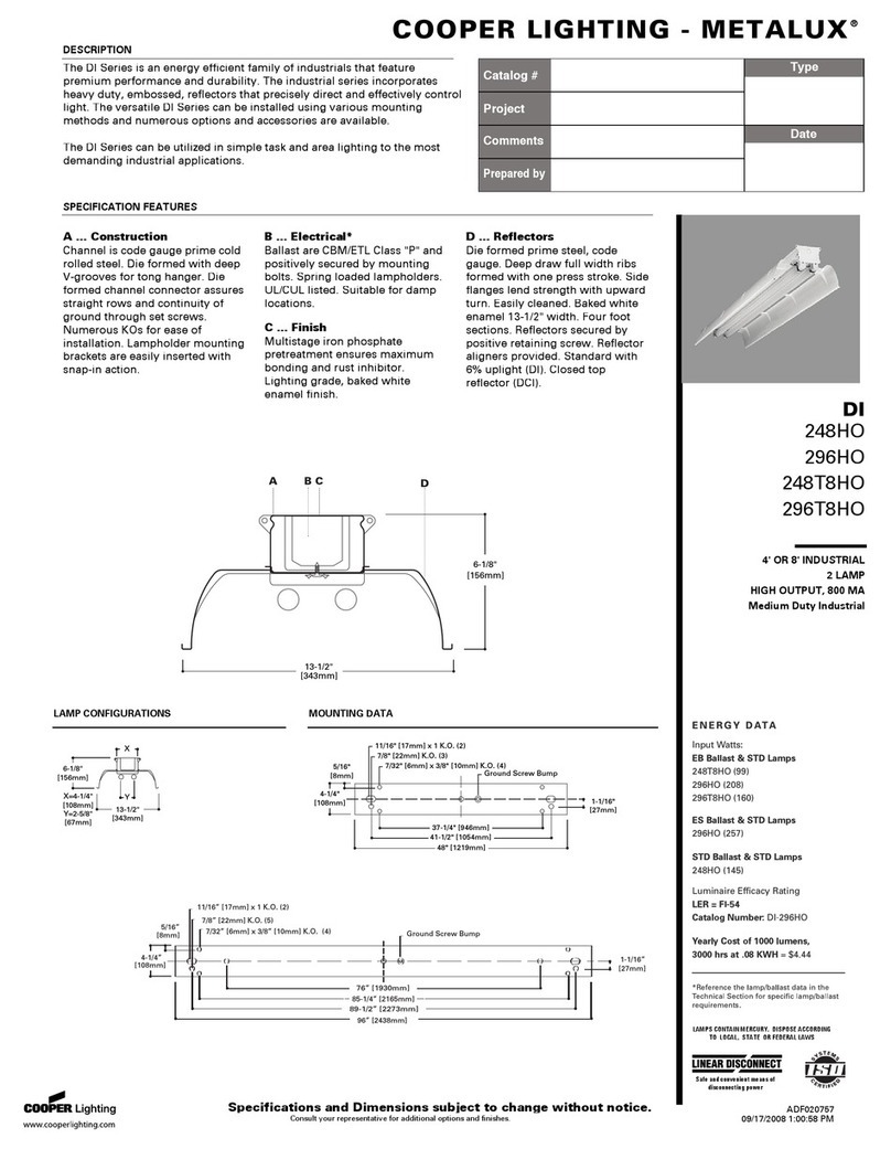
Cooper Lighting
Cooper Lighting Metalux 248HO Specifications

Philips
Philips Brisa FP28UDA Dimensions
