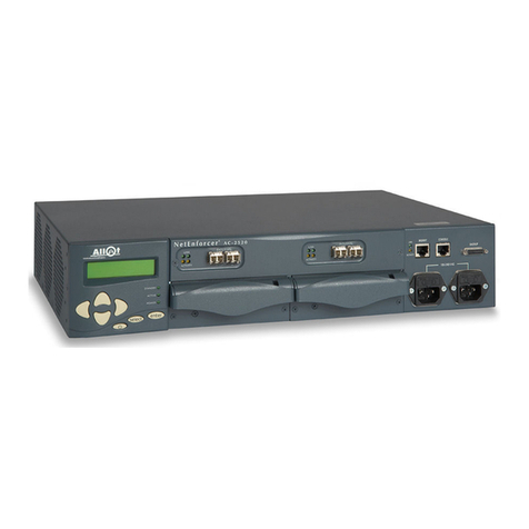
Allot NetEnforcer AC-1000 Series Installation instructions


NetEnforcer
AC-1000 Series
Policy Based Bandwidth Management
Hardware Guide
P/N D362001 R2


Important Notice
AC-1000 Series Hardware Guide
iii
Important Notice
Allot Communications Ltd. ("Allot") is not a party to the purchase agreement under which NetEnforcer was purchased, and
will not be liable for any damages of any kind whatsoever caused to the end users using this manual, regardless of the form of
action, whether in contract, tort (including negligence), strict liability or otherwise.
SPECIFICATIONS AND INFORMATION CONTAINED IN THIS MANUAL ARE FURNISHED FOR
INFORMATIONAL USE ONLY, AND ARE SUBJECT TO CHANGE AT ANY TIME WITHOUT NOTICE, AND
SHOULD NOT BE CONSTRUED AS A COMMITMENT BY ALLOT OR ANY OF ITS SUBSIDIARIES. ALLOT
ASSUMES NO RESPONSIBILITY OR LIABILITY FOR ANY ERRORS OR INACCURACIES THAT MAY APPEAR IN
THIS MANUAL, INCLUDING THE PRODUCTS AND SOFTWARE DESCRIBED IN IT.
Please read the End User License Agreement and Warranty Certificate provided with this product before using the product.
Please note that using the products indicates that you accept the terms of the End User License Agreement and Warranty
Certificate.
WITHOUT DEROGATING IN ANY WAY FROM THE AFORESAID, ALLOT WILL NOT BE LIABLE FOR ANY
SPECIAL, EXEMPLARY, INDIRECT, INCIDENTAL OR CONSEQUENTIAL DAMAGES OF ANY KIND,
REGARDLESS OF THE FORM OF ACTION WHETHER IN CONTRACT, TORT (INCLUDING NEGLIGENCE),
STRICT LIABILITY OR OTHERWISE, INCLUDING, BUT NOT LIMITED TO, LOSS OF REVENUE OR
ANTICIPATED PROFITS, OR LOST BUSINESS, EVEN IF ADVISED OF THE POSSIBILITY OF SUCH DAMAGES.
Copyright
Copyright © 1997-2007 Allot Communications. All rights reserved. No part of this document may be reproduced,
photocopied, stored on a retrieval system, transmitted, or translated into any other language without a written permission and
specific authorization from Allot Communications Ltd.
Trademarks
Products and corporate names appearing in this manual may or may not be registered trademarks or copyrights of their
respective companies, and are used only for identification or explanation and to the owners' benefit, without intent to infringe.
Allot and the Allot Communications logo are registered trademarks of Allot Communications Ltd.
NOTE: This equipment has been tested and found to comply with the limits for a Class A digital device, pursuant to Part 15 of
the FCC Rules. These limits are designed to provide reasonable protection against harmful interference when the equipment
is operated in a commercial environment. This equipment generates, uses, and can radiate radio frequency energy and, if not
installed and used in accordance with the instruction manual, may cause harmful interference to radio communications.
Operation of this equipment in a residential area is likely to cause harmful interference in which case the user will be
required to correct the interference at his own expense.
Changes or modifications not expressly approved by Allot Communication Ltd. could void the user's authority to operate the
equipment.

Important Notice
AC-1000 Series Hardware Guide
iv
Printing History
First Edition: July, 2006
Second Edition: September, 2007

NetEnforcer AC-1000 Hardware Guide
v
Table of Contents
Important Notice .......................................................................................................................... iii
Printing History.............................................................................................................................iv
Table of Contents ...........................................................................................................................v
Table of Figures........................................................................................................................... vii
CHAPTER 1: AC-1000 SERIES HARDWARE .........................................................1-1
AC-1000 Series Packing List ..................................................................................................... 1-2
NetEnforcer Front Panel ........................................................................................................... 1-3
AC-1000 Series Front Panels ................................................................................................... 1-4
LCD Panel................................................................................................................................ 1-6
Power Supply Modules............................................................................................................. 1-8
Accessories Area .................................................................................................................... 1-11
Cabling ...................................................................................................................................... 1-14
AC-1000 Series Copper.......................................................................................................... 1-14
AC-1000 Multi Mode (SX) Fiber........................................................................................... 1-16
AC-1000 Series Single Mode (LX5, LX20, ZX) Fiber.......................................................... 1-17
Connectors.............................................................................................................................. 1-18
Bypass Units.............................................................................................................................. 1-19
AC-1010 Bypass Units........................................................................................................... 1-19
AC-1020 Bypass Unit............................................................................................................. 1-23
AC-1040 Bypass Unit............................................................................................................. 1-28
Powering Up ............................................................................................................................. 1-30
Connection to AC Power........................................................................................................ 1-30
Connection to DC Power........................................................................................................ 1-30
Grounding............................................................................................................................... 1-31
Powering Up Via LCD Panel ................................................................................................. 1-32
CHAPTER 2: PLACEMENT IN THE NETWORK..................................................2-1
CHAPTER 3: SETTING UP THE NETENFORCER................................................3-1
Configuring Via a Terminal or Telnet...................................................................................... 3-1

NetEnforcer AC-1000 Hardware Guide
vi
Configuring Via the LCD Panel..............................................................................................3-12
CHAPTER 4: REDUNDANCY.................................................................................... 4-1
Enabling Redundancy ................................................................................................................4-1
Parallel Redundancy ................................................................................................................4-13
Status Indicators in Parallel Redundancy Mode .....................................................................4-14
Secondary NetEnforcer Activation.........................................................................................4-15
Active Redundancy...................................................................................................................4-17
Failover...................................................................................................................................4-17
Policy Configuration...............................................................................................................4-17
Connecting the NetEnforcer in Active Redundancy...............................................................4-18
Active Redundancy for the AC-1020......................................................................................4-18
Active Redundancy for the AC-1040......................................................................................4-18
Serial Redundancy....................................................................................................................4-19
NetEnforcer Failover...............................................................................................................4-20
Serial Redundancy in Mesh Topologies .................................................................................4-21
CHAPTER 5: HARDWARE SPECIFICATIONS ..................................................... 5-1
Dimensions ...............................................................................................................................5-1
Power Requirements.................................................................................................................5-1
Operating Environment.............................................................................................................5-2
Standards, Compliance and Certifications...............................................................................5-3
CHAPTER 6: FIREWALL PORT REFERENCE..................................................... 6-1
CHAPTER 7: ÉQUIPEMENT DE SÉRIE AC-1000 .................................................7-1
Mises en garde d’ordre général:................................................................................................7-2
Remarques d’ordre général:......................................................................................................7-4
Spécifications matérielles ...........................................................................................................7-5
Dimensions ...............................................................................................................................7-5
Spécifications requises..............................................................................................................7-5

NetEnforcer AC-1000 Hardware Guide vii
Table of Figures
Figure 1-1 – Front Panel: AC-1000 Series................................................................................... 1-3
Figure 1-2 – Front Panel: AC-1010 Copper................................................................................. 1-4
Figure 1-3 – Front Panel: AC-1020 Fiber.................................................................................... 1-4
Figure 1-4 – Front Panel: AC-1040 Copper................................................................................. 1-5
Figure 1-5 – NetEnforcer LCD Panel .......................................................................................... 1-6
Figure 1-6 – Dual SC Connector (Multi Mode Fiber)................................................................ 1-18
Figure 1-7 – Dual LC Connector (Single Mode Fiber).............................................................. 1-18
Figure 1-8 – Single Copper Bypass Unit ................................................................................... 1-19
Figure 1-9 – Connecting the NetEnforcer AC-802 Copper to the Single Copper Bypass Unit. 1-20
Figure 1-10 –Single Fiber Bypass Unit – Multi Mode............................................................... 1-21
Figure 1-11 –Single Fiber Bypass Unit – Single Mode ............................................................. 1-21
Figure 1-12 – Connecting NetEnforcer AC-1010 Fiber to Single Fiber Bypass Unit – Multi Mode
............................................................................................................................................ 1-22
Figure 1-13 – Connecting the NetEnforcer AC-1020 to Double Copper Bypass Unit.............. 1-24
Figure 1-14 – Double Fiber Bypass Unit - MultiMode.............................................................. 1-25
Figure 1-15 – Double Fiber Bypass Unit – Single Mode........................................................... 1-26
Figure 1-16 – Connecting the NetEnforcer AC-1020 to Double Fiber Bypass Unit – Single Mode
............................................................................................................................................ 1-27
Figure 1-17 – Multi-Port Copper Bypass Unit........................................................................... 1-28
Figure 3-1 – NetEnforcer Setup Menu......................................................................................... 3-2

NetEnforcer AC-1000 Hardware Guide
viii
Figure 3-2 – Current Configuration (1)........................................................................................3-4
Figure 3-3 – Current Configuration (2)........................................................................................3-5
Figure 3-4 – Network Configuration............................................................................................3-6
Figure 3-5 – Password..................................................................................................................3-9
Figure 3-6 – Time Setup.............................................................................................................3-10
Figure 4-1 – NIC Tab AC-1010 – NetXplorer Configuration......................................................4-3
Figure 4-2 – Networking Tab AC-1010 – NetXplorer Configuration..........................................4-4
Figure 4-3 – NIC Tab AC-1020 – NetXplorer Configuration......................................................4-7
Figure 4-4 – Networking Tab AC-1020 – NetXplorer Configuration..........................................4-8
Figure 4-5 – NIC Tab AC-1040 – NetXplorer Configuration....................................................4-11
Figure 4-6 – Networking Tab AC-1040 – NetXplorer Configuration........................................4-12
Figure 4-7 – Serial Redundancy – Normal Scenario..................................................................4-19
Figure 4-8 – Serial Redundancy – Failover Scenario.................................................................4-20
Figure 4-9 – Serial Redundancy – Bypass Scenario...................................................................4-21
Figure 4-10 – Serial Redundancy – Mesh Scenario ...................................................................4-22

NetEnforcer AC-1000 Hardware Guide
1-1
Chapter 1: AC-1000 Series Hardware
This chapter describes the NetEnforcer AC-1000 series hardware and the initial
installation and setup of the device. The NetEnforcer is a transparent learning bridge
that is IEEE 802.1-compliant and works with a Bypass Unit to ensure that data
continues flowing should any hardware or software problem occur. While the
NetEnforcer is bypassed, all traffic goes through passive elements only and still allows
the network to function.
NetEnforcer AC-1000 series offers carrier-grade design with redundant critical
components for fail-safe operation. Redundant hardware components include system
fans and dual hot-swappable power supplies. The NetEnforcer AC-1000 series is
designed to meet ETSI standards.
All AC-1000 series units come with an additional Bypass Unit.
CAUTION All AC-1000 Series models only function when the appropriate
Bypass Unit is connected to it. This is to ensure continuous service
in the event of failure.
NOTE AC-1000 NetEnforcer NIC default factory setting is always Auto-
Negotiation enabled, with the exception of the AC-1010 Copper whose
default NIC setting is 1000 full, Auto-Negotiation disabled.
It is recommended to keep the NetEnforcer’s default setting. Changing
NIC settings is done via LCD panel only.
Several NetEnforcer models are available to support large and small sites and different
data network speeds.
All NetEnforcer AC-1000 series units support 1M connections (2M flows), 2,000 pipes
and 8,000 Virtual Channels. Additional Pipes and Virtual Channels can also be
purchased separately per device. Allot basic management software is included with all
AC-1000 series devices. Allot NetXplorer Centralized Management software can be
purchased for any AC-1000 series device using software version S7.1.0 or later,
replacing the basic management.

Chapter 1: AC-1000 Series Hardware
NetEnforcer AC-1000 Hardware Guide
1-2
The NetEnforcer AC-1010 is a general-purpose carrier grade device with one line (two
port) connectivity. The device is available with either AC or DC power supplies and
with copper, SX fiber, LX5 fiber, LX20 fiber or ZX fiber interface connectors. The AC-
1010 may be ordered with an upgradable throughput of 155 Mbps, 310 Mbps, 622
Mbps or 1 Gbps.
The NetEnforcer AC-1020 is intended to be used in a mesh network configuration
where redundancy is kept by connecting each path to a different network device. The
AC-1020 has two line (four port) connectivity. The device is available with either AC or
DC power supplies and with copper, SX fiber, LX5 fiber, LX20 fiber or ZX fiber
interface connectors. The AC-1020 may be ordered with an upgradable throughput of
155 Mbps, 310 Mbps, 622 Mbps, 1 Gbps or 2 Gbps.
The NetEnforcer AC-1040 is a carrier grade unit intended for large service providers or
carriers with four line (eight port) connectivity. The unit is available with either AC or
DC power supplies and with copper interface connectors. The AC-1040 is provided
with a non-upgradable throughput of 400 Mbps,
AC-1000 Series Packing List
Verify that the following items are included with NetEnforcer:
•NetEnforcer (hardware with pre-installed software)
•NetEnforcer Hardware Guide
•Two mains power cables according to National Electrical Code (NEC) with
molded IEC sockets
•1 Serial Console Cable
•1 Ethernet Cross Management Cable
•2 19" Side Mounting Brackets
•8 Mounting Bracket Screws
•1 D-type High Density Backup Cable
NOTE The maximum Ethernet cable length is generally up to 50 meters.

Chapter 1: AC-1000 Series Hardware
NetEnforcer AC-1000 Hardware Guide 1-3
NetEnforcer Front Panel
The AC-1000 series connects to your network via Link Connection connectors. The
LCD panel, connectors and LED indicators on the front panel, are shown in the
following diagrams.
The front panel of each AC-1000 series unit is separated into four areas as shown
below:
Figure 1-1 – Front Panel: AC-1000 Series
The front panel of NetEnforcer is laid out as follows:
•LCD panel, described on page 1-6
•The Link Connections area
•Power Supply Modules, described on page 1-8.
•Accessory area, including the following:
•Management Port, described on page 1-11
•Management LEDs, described on page 1-12
•Console Connector described on page 1-12
•Backup High Density D-type Connector (see Bypass Units on page 1-
19)
•Two power cable connectors described on page 1-13.

Chapter 1: AC-1000 Series Hardware
NetEnforcer AC-1000 Hardware Guide
1-4
AC-1000 Series Front Panels
AC-1010 Front Panels
Figure 1-2 – Front Panel: AC-1010 Copper
AC-1020 Front Panel
Figure 1-3 – Front Panel: AC-1020 Fiber

Chapter 1: AC-1000 Series Hardware
NetEnforcer AC-1000 Hardware Guide 1-5
AC-1040 Front Panels
Figure 1-4 – Front Panel: AC-1040 Copper
CAUTION CLASS 1 LASER PRODUCT. DANGER!
Invisible laser radiation when opened.
AVOID DIRECT EXPOSURE TO BEAM.

Chapter 1: AC-1000 Series Hardware
NetEnforcer AC-1000 Hardware Guide
1-6
LCD Panel
The NetEnforcer LCD panel provides an indication of traffic usage and enables you to
configure NetEnforcer directly without the need to connect a terminal. You can also
start, reboot and shutdown NetEnforcer from the front panel.
On/Off Enter
Up Arrow
Display Area
Sel ec t
Power Indicator
Active Indicator
Standby Indicator
Left Arrow
Right Arrow
Down Arrow
On/Off Enter
Up Arrow
Display Area
Sel ec t
Power Indicator
Active Indicator
Standby Indicator
Left Arrow
Right Arrow
Down Arrow
Figure 1-5 – NetEnforcer LCD Panel
For a description of how to configure NetEnforcer using the LCD panel, refer to
Configuring Via the LCD Panel, page 3-12.
For a description of the Standby, Active and Power LEDs, refer to Interface Status
Indicators, page 1-8.

Chapter 1: AC-1000 Series Hardware
NetEnforcer AC-1000 Hardware Guide 1-7
Unit Status Indicators
The modes of operation of the Standby, Active and Power LEDs on the LCD panel are
described in the table below.
Indicator Status NetEnforcer Status
Standby On Two NetEnforcers are connected in Parallel Redundancy
mode and this NetEnforcer is the secondary system.
Off This NetEnforcer is the primary system. If you have one
NetEnforcer, this should be the normal state of the LED. If
you have two NetEnforcers configured in Parallel
Redundancy mode, this NetEnforcer is the primary system.
Active On NetEnforcer is in Active mode.
Off NetEnforcer is in Bypass mode, or this is the secondary
NetEnforcer in a Parallel Redundancy configuration and it
is not active. Traffic passes through NetEnforcer with no
Quality of Service or traffic shaping.
Power On NetEnforcer is powered up.
Off NetEnforcer is shut down.
Table 1-1 – Standby/Active/Power LED Conditions

Chapter 1: AC-1000 Series Hardware
NetEnforcer AC-1000 Hardware Guide
1-8
Interface Status Indicators
The modes of operation of the Link (External and Internal) LEDs are described in the
table below.
Link Status Indicators – AC-1010/1020
Ext/Int LED NetEnforcer Status
Green A lit green LED indicates that a link is detected.
Amber A blinking amber LED indicates that traffic is detected on
the interface.
Off An unlit LED indicates that neither links nor activities were
detected.
Table 1-2 – External/Internal LED Conditions – AC-1010/1020
Link Status Indicators – AC-1040
Ext/Int LED NetEnforcer Status
Green A lit green LED indicates that a link is detected.
Red A blinking red LED indicates that traffic is detected on the
interface.
Off An unlit LED indicates that neither links nor activities were
detected.
Table 1-3 – External/Internal LED Conditions – AC-1040
Power Supply Modules
NetEnforcer includes two hot-swappable power supply modules and a dual line feed for
Redundancy purposes. Each line feed is driving one power supply.

Chapter 1: AC-1000 Series Hardware
NetEnforcer AC-1000 Hardware Guide 1-9
NOTE The AC power supply automatically adapts to voltages between 100 V and
240 V, 50/60 Hz. The DC power supply automatically adapts to voltages
of 48 V or 60 V DC.
This equipment is for use in a restricted access area by qualified
personnel only. To avoid shock, do not perform any servicing other than
those contained in the unpacking instructions.
Should you need to, you can replace one of the power supplies while NetEnforcer is
connected and operating. Replacing a power supply while the unit is operating is
possible since the remaining power supply will take the full load and maintain full
operation.
NOTE To remove a power supply module, undo the two screws in the lower left
and right corners, lift the handle and slide the module out.

Chapter 1: AC-1000 Series Hardware
NetEnforcer AC-1000 Hardware Guide
1-10
Each power supply has two LEDs located beneath the power supply handles.
Model Copper/Fiber options Power inlet options
AC 1010 Transceiver SFP Copper
Transceiver SFP SX
Transceiver SFP LX 5
Transceiver SFP LX 20
Transceiver SFP ZX
AC/DC
AC 1020 Transceiver SFP Copper
Transceiver SFP SX
Transceiver SFP LX 5
Transceiver SFP LX 20
Transceiver SFP ZX
AC/DC
AC 1040 Copper AC/DC
CAUTION The power entry modules (AC supply option) include two fuses (T2A
250 V, 5 x 20 mm) at each power entry. One is a spare fuse for
replacement purposes. You can open the fuse box and change when
necessary. For continued protection against risk of fire, replace only
with same type and rating of fuse.
Disconnect the product from the power line before removing the
cover. Any adjustment and maintenance of the opened device
should be done only while the device is disconnected from its
source of power and should only be performed by qualified
personnel
This manual suits for next models
3
Table of contents
Other Allot Server manuals
Popular Server manuals by other brands
Red Hat
Red Hat DIRECTORY SERVER 8.1 - USING RED HAT CONSOLE... Using instruction
Vingtor Stentofon
Vingtor Stentofon AlphaCom XE Series Installation, configuration & operation
Plat Home
Plat Home OpenBlocks IoT VX2 Developer's guide
Dell
Dell Active Fabric Manager Deployment guide
Meridian
Meridian Sooloos Ensemble quick start guide
HP
HP ProLiant DL380 Gen9 Maintenance and service guide
