7
Furnace Operation
In the heating mode, gas is burned and the products of
combustion are drawn through a heat exchanger by an
induced draft blower. The flue gases are then exhausted
from your home through a flue pipe system. The furnace
circulator blower passes indoor air over the heat ex-
changer and then through the conditioned space.
Thermostat Functions
This furnace requires a two-stage thermostat. A two
stage thermostat controls which firing rate is used
depending on the temperature difference between the
set point and the room temperature. If the difference is
small, the thermostat will energize the furnace on the low
stage. If the temperature difference is high, the thermo-
stat will energize the furnace on high stage. A two stage
thermostat and furnace properly used will maintain a
much tighter control of temperature than a conventional
single stage thermostat and furnace.
For optimal operation of this furnace, set the thermostat to
the temperature desired. Do not over adjust the thermostat
to turn the heat on. This will cause the high stage heat to
come on when the low stage heat could have satisfied the
demand. Setting the temperature to the desired tempera-
ture will minimize temperature fluctuations.
In addition, there are thermostats that automatically
switch from Heating to Cooling and with night setbacks.
The night set-back, or multiple set-back type, will adjust
the temperature at night or during the day when no one
is at home, saving energy and lowering fuel bills.
General Information
Fan Switch
Cool/Heat
Switch
Cool/Heat
Temperature
Control Dials
Room Temperature
Thermostat
System
Switch
Fan
Switch Action
OFF
UTO None
COOL AUTO System only cools, fan
cycles off and on.
COOL ON System only cools, fan
runs all the time.
HEAT AUTO System only heats, fan
cycles off and on.
HEAT ON System only heats, fan
runs all the time.
OFF ON No heating or cooling,
fan runs all the time.
Typical Thermostat
General Information
WARNING
Electrical components are contained in both
compartments. To avoid electrical shock, injury or
death, do not remove any internal compartment
covers. Contact a qualified servicer at once if an
abnormal condition is noticed.
Notice:
Do not use this furnace if any part has been under water.
Immediately call a qualified servicer to inspect the
furnace and to replace any part of the control system and
any gas control which has been under water.
Keep both doors in place except for inspection and
maintenance. An interlock switch prevents furnace
operation if the blower door is not in place.
Dehumidistat
The dehumidistat (not included in furnace) controls
excessive humidity in the home. To operate, set the
dehumidistat to the desired relative humidity level. If the
cooling system is wired to the furnace controls and is
running, the furnace blower will lower its speed to
improve dehumidification, if needed.
Refer to Specification Sheet for available dehumidistats
(not included in furnace).
Self Diagnostic Electronic Control Module
Certain furnace models are equipped with a self-diag-
nostic electronic control module. If a furnace component
is not operating properly, the control module will repeat-
edly flash a red light on and off in a factory-programmed
sequence, depending on the problem encountered.
If a furnace equipped with a self-diagnostic module is not
operating properly, look through the observation window
in the blower access door and make note of the number
of flashes in the sequence. Contact a qualified servicer
for further information. Do not attempt to troubleshoot the
problem yourself.
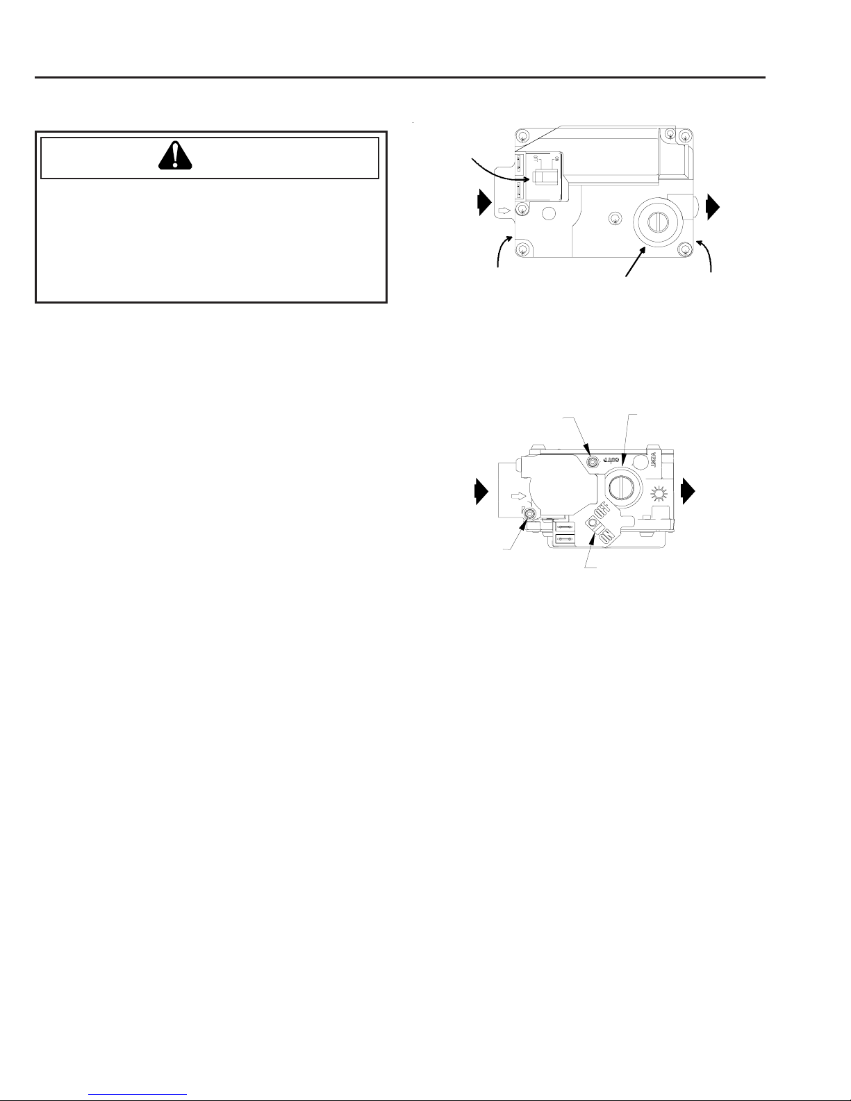
Gas Valve
The gas valve regulates gas flow to the burners in
response to input from the integrated control module.
Igniter
The furnace has an electronic ignition device which lights
the burners automatically. Never try to light the burners
by hand.
Blowers
This furnace has an induced draft blower which draws
flue products through the heat exchanger and exhaust
them outdoors. It also has a circulator or main blower
that passes indoor air over the heat exchanger and into
the conditioned space. Both blowers are permanently
lubricated, no further oiling is required.