Amana AMC4080AA User manual

Part No.: 8101P611-60
Code No.: DE68-02900A
Installation Instructions
READ CAREFULLY. KEEP THESE INSTRUCTIONS.
IMPORTANT SAFETY INSTRUCTIONS
WARNING
Before attempting the installation of this kit, be sure to unplug the oven from wall receptacle.
Your ovenis designed to be installed underproperly constructed,good condition wood or metal cabinets thatare sturdy enoughto support
the items you have in the cabinet, plus an additional 41 kg (90 pounds) from the cabinet bottom.
Empty the contents of your selected cabinet and the delicate items in adjoining cabinets.
(
NOTE
: When drilling the holes, the vibration could cause damage to fragile items such as crystal or china.)
Now, you must inspect your cabinets. If any of the following conditions exist, then it is your personal responsibility to test the cabinets or
contact a qualified cabinet maker.
1.
Separation of joints between the bottom shelf and the cabinet structure.
2.
Splitting, cracking or other signs of deterioration.
3.
Check the number of screws used to install your cabinets. If your cabinet is attached to the wall with only two screws at the top, then
you must add two screws at the bottom to firmly secure your cabinet to the wall. When adding the screws, be sure that they enter wall
studs with at least 1.3 cm (1/2”) penetration.
4.
On wood cabinets, the bottom shelf must be at least .48 cm (3/16”) thick masonite or plywood.
5.
Be sure that the underside of the cabinet is at least 50 cm (20”) wide and 35.0cm (13 25/32”) deep. If the cabinet is less than
35.0cm(13 25/32”) deep, follow the cabinet mounting instructions catefully if you desire to mount your oven under cabinet.
To test your cabinets, place a 40 KG(90LB.) load, plus the equivalent weight of items normally stored on the shelf*, for a minimum of five
minutes.
*You may consider using jugs of water, bricks or books to obtain the test load.
PLEASE NOTE
: If your cabinet isproperly constructedand suitably installed itwill withstand thistest without anydamage; however, there
is the possibility of damage should the cabinet be incapable of supporting the additional load.
The Maytag Company is NOT RESPONSIBLE FOR ANY DAMAGE OR OTHER CONSEQUENCES resulting from the performance of
this test.
If you are unsure that your cabinets are suitable for this type of installation you may use the oven on your countertop.
TOOLS AND PARTS
The following tools are needed for installation of your unit:
• Drill and .64cm (1/4”) drill bit
• Phillips and flat blade screwdrivers
• Nail or center punch
• Pencil and ruler
• Scissors
•Hammer
INSTALLATION PARTS LIST
The following is a list of the parts that you may need for installation of your oven.
Remove all parts from the cooking cavity and compare them with the parts list and illustration to be sure that none are missing. Use this
time to become familiar with each piece.

PARTS LIST
1. 3 Sets of bolts
2. 4-washers-A
3. 4-washers-B
4. 1-Template
Upon completing your check of the parts list, read all instructions completely before starting the installation. This will help you to become
familiar with the process and make installation easier.
(
NOTE
: It is suggested that you gather all needed tools and installation parts in one location.)
PREPARATIONS
Open the template and detach both segments along the dashed line with scissors. You should have two separate pieces.
• Template 1
• Template 2
TWO MOUNTING METHODS
There are two mounting methods described in this booklet that can be used.
1.
Countertop Method
You can use this method if you decide not to cabinet mount your oven.
To use your oven as a countertop model, simply position the oven on the desired counter and plug the electrical cord into a three
prong (grounded)wall receptacle.
2.
Cabinet Mounting Method
This method is for mounting youroven under a cabinet and uses thetemplate, 4-washers and one setof screws. Before using this method,
the 4 plastic plug buttons on the top of the oven must be removed. This can be done by placing a thin flat blade screwdriver between the
plug button and the oven top and raising gently, taking care to avoid acratching the oven top.
OVEN MAY BE MOUNTED TO CABINETS WITH OR WITHOUT A FRONT RAIL.
If you drill the 4 mounting holes from the inside of the cabinet - place the
front edge of the template at the front edge of the cabinet.
Drill the 4 holes 1/4" DIA. as described in the installation instruction booklet.
If you drill the mounting holes from the bottom side of the cabinet -
measure the thickness of the front rail and cut that amount off the front of
the template. Use the cutting lines to insure a straight cut. Place the cut
edge against the back side of the front rail and position the template flat
against the bottom side of the cabinet.
Drill the 4 holes 1/4" DIA. as described in the installation instruction booklet.
IMPORTANT
Read the installation booklet for complete instructions before beginning installation.
Template must lay flat against the cabinet when locating the holes.
(See installation booklet for complete instructions.)
TEMPLATE 1
TEMPLATE 2
INSTRUCTIONS
15
25/64"
15
25/64"
DETACHDETACH
TEMPLATE
CUT LINES
CABINET
FRONT
(A)
(B)
or
TEMPLATE
ON TOP SIDE
FRONT FRONT
TEMPLATE
CUT LINES
1 1/4 INCH
1/2 INCH
1/4 INCH
1 INCH
CABINET FRONT
DETACH
HOLE CENTRE LINE
HOLE CENTRE LINE
MICROWAVESIDE
MICROWAVESIDE
HOLE CENTRE LINE
DETACH
HOLE CENTRE LINE
CABINET
FRONT
FRONT RAIL
THICKNESS
TEMPLATE ON
BOTTOM SIDE
CUT EDGE
1243
TEMPLATE 1
TEMPLATE 1
15
25/64"
DETACHDETACH
DETACH
HOLE CENTRE LINE
DETACH
HOLE CENTRE LINE
If you drill the 4 mounting holes from the inside of the cabinet - place the
front edge of the template at the front edge of the cabinet.
Drill the 4 holes 1/4" DIA. as described in the installation instruction booklet.
If you drill the mounting holes from the bottom side of the cabinet -
measure the thickness of the front rail and cut that amount off the front of
the template. Use the cutting lines to insure a straight cut. Place the cut
edge against the back side of the front rail and position the template flat
against the bottom side of the cabinet.
Drill the 4 holes 1/4" DIA. as described in the installation instruction booklet.
IMPORTANT
Read the installation booklet for complete instructions before beginning installation.
Template must lay flat against the cabinet when locating the holes.
(See installation booklet for complete instructions.)
TEMPLATE 2
TEMPLATE 2
INSTRUCTIONS
15
25/64"
TEMPLATE
CUT LINES
CABINET
FRONT
(A)
(B)
or
TEMPLATE
ON TOP SIDE
FRONT FRONT
TEMPLATE
CUT LINES
1 1/4 INCH
1/2 INCH
1/4 INCH
1 INCH
CABINET FRONT
HOLE CENTRE LINE
HOLE CENTRE LINE
MICROWAVESIDE
MICROWAVESIDE
CABINET
FRONT
FRONT RAIL
THICKNESS
TEMPLATEON
BOTTOM SIDE
CUT EDGE
CABINET
(SIDE VIEW)
COUNTERTOP
CABINET
(SIDE VIEW)
COUNTERTOP

DRILLING APPROACH
You have two options for drilling the mounting holes for your oven.
First, you can drill from inside of the cabinet if you have adequate space and your shelves are removable.
Second, you can drill from the bottom.
If possible, it is generally easier to work from the inside of the cabinet. Use the instructions applicable to the approach you select. Make
sure you use the template properly depending whether you drill holes from the inside or bottom side of the cabinet.
INSTRUCTIONS FOR DRILLING FROM INSIDE
If you cannot drill from the inside, go to Instructions for Drilling From Bottom.
1.
If your cabinet is less than 35cm(13 25/32”) deep, cut off the front edge of Template 2 the amount by which the cabinet depth is less
than 35cm(13 25/32”), using the template cut lines as a fuide. Place Template2 inside cabinet. Cut around door jam and if necessary,
corners to make template fit.(The front edge of template must be even with the front edge of the cabinet.) Place Template 2 in
cabinet.
NOTE
: For cabinets with a recessed shelf you must measure the thickness of the front rail and cut that amount off the front edge of
Template 2 using the template cut lines as a guide. This will allow Template 2 to lay flat in the shelf.
2.
If you have a partition in the cabinet, you must do the following:
• Cut Template 2 into two pieces to fit each side of the partition.
• Position one piece of Template 2 inside the cabinet, making sure that the front edge is even with the front edge of cabinet.
• Position Template 1 on front of the cabinet so that the arrow is aligned with the hole center line on Template 2.
• Position remaining piece of Template 2 inside cabinet and align the hole center lines with arrows on Template 1 so that
distance from right hole center to left hole center measures the distance indicated on the template. (You will have to cut
excess paper from the middle of Template 2 to make it lay flat.)
• Position the remaining piece of Template 2 inside cabinet.
• Check again to make sure that the hole center lines on Template 2 are straight and that the distance from the right to left
drilling holes measures the distance indicated on the template.
• Go to Drilling the Mounting Holes.
INSTRUCTIONS FOR DRILLING FROM BOTTOM
1.
If you have a front rail, measure the thickness and cut that amount off the front edge of Template 2 using the template cut lines as a
guide.
2.
Place cut edge of Template 2 against the back side of the front rail and position it flat against the bottom side of the cabinet.
NOTE
: On some cabinets a small bracket or glue block is used between the overhang and the underside of the cabinet bottom. If this is
true of your cabinets, cut Template 2 to fit around the bracket or glue block so that it will be flat on the cabinet bottom when attached.
3.
If you have a partition you must do the following:
• Cut Template 2 into two pieces to fit on each side of the partition.
• Position one piece of Template 2 under the cabinet. (The cut line along the front edge of Template 2 must be placed
against the back of the front rail.)
• Attach Template 1 to rear of cabinet and align arrows with hole center line on Template 2.

• Position remaining piece of Template 2 under the cabinet and align the hole center lines with arrows on Template 1 so
that the distance from right hole center to left hole center measures the distance indicated on the templates. (You may
have to cut excess paper from middle of the template to make it lay flat.)
• Position Template 2. (The cut line along the front edge of template must be placed against the back of the front rail.)
DRILLING THE MOUNTING HOLES
While drilling, it is recommended that safety glasses be worn to prevent possible eye damage from cabinet shavings.
1.
Use a center punch or nail to make an indentation for centering the drill bit.
2.
Drill through Template 2 at the four black drilling holes indicated on the template. (Drill should be held straight to ensure proper
alignment of bolts.)
3.
After drilling the four holes, remove the template and clean the drill holes.
SELECTING YOUR MOUNTING BOLTS
1.
You should have three sets of bolts of varying lengths in the installation package. select one bolt of each size.
2.
Hold each bolt against the cabinet front rail. pick the bolt that extends beyond top of the bottom shelf by. 48 cm (3/6") to 2.54 cm (1").
this will be the bolt length needed for your cabinets.
NOTE
: It is important to pick the correct bolt length needed for your cabinets. If the bolt is too short it won't reach the oven. If the bolt is
too long, it will not permit oven to be drawn up to the cabinet snugly.
3.
From inside the cabinet, insert the bolts through the mounting straps and then into the drilled holes.
MOUNTING THE OVEN
To aid installation, we suggest that you use some solid support suchas books to holdthe oven while you are securing it withthe mounting
bolts.
Make sure that whatever you use is stacked or cut as close as possible to the height needed for the oven to reach the cabinet bottom.
1.
Place the oven on the support and move into position. Lift oven, aligning the mounting holes on the oven with the bolts. Do not grip
the door handle to help lift the oven.
2.
Insert bolts into mounting holes on the oven. Tighten the bolts to secure oven to thebottom of the cabinet.(Alternate between bolts so
that oven is drawn up evenly.)
3.
Once oven is securely in place, plug power cord into three prong (grounded) wall receptacle.
2.54cm~0.5cm
(1"~3/16")
TOP OF BOTTOM SHELF
Printed in Malaysia

Part No.: 8101P611-60
Código No.
: DE68-02900A
Instrucciones de instalación
LÉALAS DETENIDAMENTE. Conserve estas instrucciones.
INSTRUCCIONES DE SEGURIDAD IMPORTANTES
ADVERTENCIA
Antes de comenzar la instalación de este kit, asegúrese de que el horno esté desenchufado.
Este horno se ha diseñado para su instalación bajo armarios de madera o metal apropiados y bien acondicionados, lo suficientemente
resistentes como para soportar los elementos que desee colocar dentro de ellos más un peso adicional de 41 kg colgado de la parte
inferior.
Vacíe el armario seleccionado y retire los objetos que pudiera haber en los armarios adyacentes.
(
NOTA
: La vibración producida al perforar los orificios puede dañar los elementos frágiles, como el cristal o la porcelana.)
Ahora proceda a inspeccionar los armarios. Si se da alguna de las siguiente circunstancias, deberá comprobar personalmente la
resistencia de éstos, o ponerse en contacto con un fabricante de armarios cualificado.
1.
Separación de las juntas entre el estante inferior y la estructura del armario.
2.
Grietas, rendijas u otros signos de deterioro.
3.
Compruebe el número de tornillos usados para instalar el armario. Si está sujeto al muro mediante sólo dos tornillos en la parte
superior, deberá añadir otros dos tornillos en la parte inferior para asegurar firmemente el armario. Al colocar estos tornillos,
asegúrese de que penetren al menos 1,3 cm en el interior del muro.
4.
En armarios de madera, el grosor del tablero o del contrachapado del estante inferior debe ser de al menos 0,48 cm.
5.
Asegúrese de que la parte inferior del armario tenga como mínimo de 50 cm de anchura y 35 cm de profundidad. Si el armario tiene
menos de 35 cm de profundidad, siga cuidadosamente las instrucciones de montaje si desea montar el horno bajo el armario.
Para comprobar la resistencia del armario, coloque en el estante* un peso de 40 kg, más el peso equivalente al de los objetos que
normalmente almacena en su interior, durante al menos cinco minutos.
*Puede utilizar garrafas de agua, bricks o libros para obtener el peso de prueba.
NOTA
: Si el armario está adecuadamente fabricado y convenientemente instalado soportará esta prueba sin sufrir ningún daño; sin
embargo,existe la posibilidadde que se produzca algún daño que provocaría que el armario fuera incapaz de soportar el peso adicional.
Maytag Company NO SE HACE RESPONSABLE DE NINGÚN DAÑO U OTRAS CONSECUENCIAS resultantes de la realización de
esta prueba.
Si no está seguro de que sus armarios sean adecuados para este tipo de instalación, puede utilizar el horno colocándolo sobre la
encimera.
HERRAMIENTAS Y COMPONENTES
Se necesitan las siguientes herramientas para instalar la unidad:
• Taladro y broca de 0,64 cm (1/4")
• Destornilladores Phillips y de punta plana
• Clavo o punzón
• Lápiz y regla
• Tijeras
• Martillo
LISTA DE COMPONENTES DE LA INSTALACIÓN
A continuación se enumeran los componentes que podrían ser necesarios par la instalación del horno.
Saque todos los componentes de la cavidad de cocción y compárelos con la lista de componentes y con el dibujo para asegurarse de
que no falte ninguno. Aproveche esta operación para familiarizarse con cada una de las piezas.

LISTA DE COMPONENTES
1. 3 juegos de tornillos
2. 4 arandelas-A
3. 4 arandelas-B
4. 1 plantilla
Cuando haya acabado de comprobar la lista de componentes, lea completamente las instrucciones antes de comenzar la instalación.
Esto le ayudará a familiarizarse con el proceso y hará que la instalación le resulte más fácil.
(
NOTA
: Le sugerimos que reúna todas las herramientas necesarias y los componentes de la instalación en un solo lugar.)
PREPARACIÓN
Abra la plantilla y separe los dos segmentos a lo largo de la línea de puntos con ayuda de unas tijeras. Con ello obtendrá dos piezas
distintas.
• Plantilla 1
• Plantilla 2
DOS MÉTODOS DE MONTAJE
Puede utilizar cualquiera de los dos métodos de montaje descritos en el folleto.
1.
Método sobre encimera
Use este método si decide no montar el horno en un armario.
Para usar el horno como un modelo de encimera, colóquelo sobre la parte de la encimera que desee y conecte el cable eléctrico a
un enchufe de pared de tres orificios (con toma de tierra).
2.
Método de montaje en armario
Este método se utiliza para montar el horno en un armario, y necesita la plantilla, las 4 arandelas y el juego de tornillos. Antes de
comenzar el procedimiento, debe retirar los cuatro botones de plástico situados en la parte superior del horno. Esto se consigue
introduciendo la punta plana de un destornillador fino entre el botón y la parte superior del horno y tirando suavemente, con cuidado para
no rayar la parte superior del horno.
EL HORNO PUEDE MONTARSE EN ARMARIOS CON O SIN TOPE FRONTAL.
If you drill the 4 mounting holes from the inside of the cabinet - place the
front edge of the template at the front edge of the cabinet.
Drill the 4 holes 1/4" DIA. as described in the installation instruction booklet.
If you drill the mounting holes from the bottom side of the cabinet -
measure the thickness of the front rail and cut that amount off the front of
the template. Use the cutting lines to insure a straight cut. Place the cut
edge against the back side of the front rail and position the template flat
against the bottom side of the cabinet.
Drill the 4 holes 1/4" DIA. as described in the installation instruction booklet.
IMPORTANT
Read the installation booklet for complete instructions before beginning installation.
Template must lay flat against the cabinet when locating the holes.
(See installation booklet for complete instructions.)
TEMPLATE 1
TEMPLATE 2
INSTRUCTIONS
15
25/64"
15
25/64"
DETACHDETACH
TEMPLATE
CUT LINES
CABINET
FRONT
(A)
(B)
or
TEMPLATE
ON TOPSIDE
FRONT FRONT
TEMPLATE
CUT LINES
1 1/4 INCH
1/2 INCH
1/4 INCH
1 INCH
CABINET FRONT
DETACH
HOLE CENTRE LINE
HOLE CENTRE LINE
MICROWAVESIDE
MICROWAVESIDE
HOLE CENTRE LINE
DETACH
HOLE CENTRE LINE
CABINET
FRONT
FRONT RAIL
THICKNESS
TEMPLATEON
BOTTOM SIDE
CUT EDGE
1243
TEMPLATE 1
TEMPLATE 1
15
25/64"
DETACHDETACH
DETACH
HOLE CENTRE LINE
DETACH
HOLE CENTRE LINE
If you drill the 4 mounting holes from the inside of the cabinet - place the
front edge of the template at the front edge of the cabinet.
Drill the 4 holes 1/4" DIA. as described in the installation instruction booklet.
If you drill the mounting holes from the bottom side of the cabinet -
measure the thickness of the front rail and cut that amount off the front of
the template. Use the cutting lines to insure a straight cut. Place the cut
edge against the back side of the front rail and position the template flat
against the bottom side of the cabinet.
Drill the 4 holes 1/4" DIA. as described in the installation instruction booklet.
IMPORTANT
Read the installation booklet for complete instructions before beginning installation.
Template must lay flat against the cabinet when locating the holes.
(See installation booklet for complete instructions.)
TEMPLATE 2
TEMPLATE 2
INSTRUCTIONS
15
25/64"
TEMPLATE
CUT LINES
CABINET
FRONT
(A)
(B)
or
TEMPLATE
ON TOP SIDE
FRONT FRONT
TEMPLATE
CUT LINES
1 1/4 INCH
1/2 INCH
1/4 INCH
1 INCH
CABINET FRONT
HOLE CENTRE LINE
HOLE CENTRE LINE
MICROWAVESIDE
MICROWAVESIDE
CABINET
FRONT
FRONT RAIL
THICKNESS
TEMPLATEON
BOTTOM SIDE
CUT EDGE
CABINET
(SIDE VIEW)
COUNTERTOP
CABINET
(SIDE VIEW)
COUNTERTOP

MÉTODOS DE TALADRADO
Existen dos opciones para perforar los orificios de montaje para el horno.
La primera consiste en perforar desde el interior del armario, en caso de que disponga del espacio adecuado para hacerlo y de que los
estantes sean desmontables.
La segunda consiste en perforar desde la parte inferior.
Por lo general, es más fácil trabajar desde el interior del armario, si ello es posible. Siga las instrucciones que correspondan al método
que haya elegido. Asegúrese de que utiliza la plantilla adecuada, según el lugar desde donde perfore los orificios del armario.
INSTRUCCIONES PARA EL TALADRADO DESDE EL INTERIOR
Si no puede taladrar desde el interior, siga las "Instrucciones para el taladrado desde la parte inferior".
1.
Si su armario tiene menos de 35 cm de profundidad, corte de la parte frontal de la plantilla 2 la medida en que la profundidad del
armario sea menor de 35 cm; utilice para ello las líneas de corte de la plantilla como referencia. Coloque la plantilla 2 dentro del
armario. Recorte alrededor de los cierres de la puerta y de las esquinas, si es necesario, para conseguir que la plantilla ajuste (el
borde frontal de la plantilla debe estar igualado con el borde frontal del armario). Coloque la plantilla 2 dentro del armario.
NOTA
: En armarios con un estante empotrado, debe medir el grosor del tope frontal y recortar esta cantidad del borde frontal de la
plantilla 2 usando las líneas de corte de la plantilla como guía. Esto permitirá que la plantilla 2 pueda colocarse plana en el estante.
2.
Si el armario tiene una partición, deberá hacer lo siguiente:
• Corte la plantilla 2 en dos partes que se ajusten a cada lado de la partición.
• Coloque una pieza de la plantilla 2 dentro del armario, comprobando que el borde frontal esté igualado con el borde
frontal del armario.
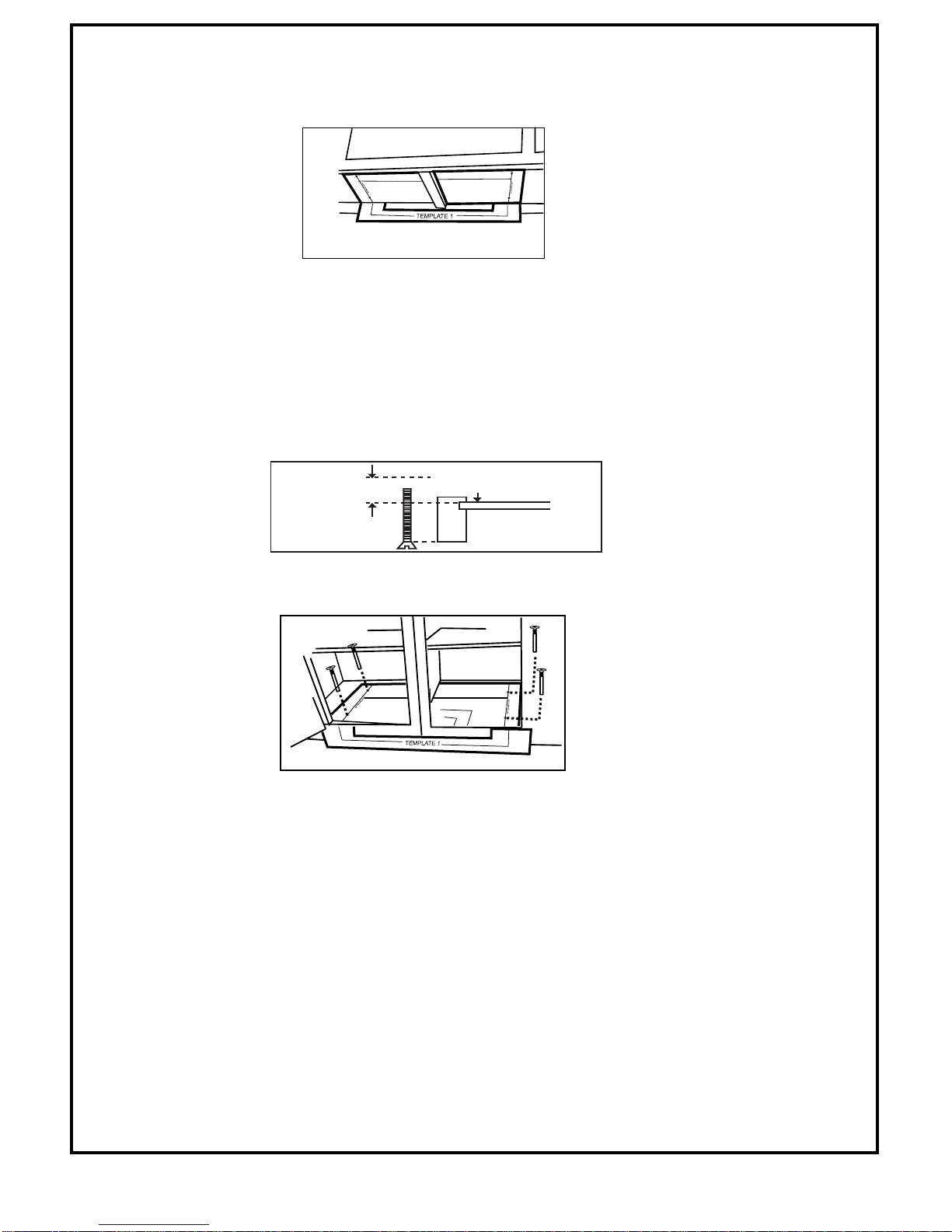
• Coloque la plantilla 1 en el frente del armario, de manera la flecha se alinee con la línea del centro del orificio de la
plantilla 2.
• Coloque la otra pieza de la plantilla 2 dentro del armario y alinee las líneas del centro de los orificios con las flechas de
la plantilla 1 de manera que la distancia desde el centro del orificio derecho al centro del orificio izquierdo coincida con la
distancia indicada en la plantilla. (Deberá cortar el papel sobrante de la parte media de la plantilla 2 para permitir que
ésta se pueda colocar plana.)
• Coloque la otra pieza de la plantilla 2 dentro del armario.
• Haga una nueva comprobación para asegurarse de que las líneas del centro de los orificios de la plantilla 2 estén rectas
y que la distancia entre los orificios de perforación izquierdo y derecho coincide con la distancia indicada en la plantilla.
• Vaya a "Taladrado de los orificios de montaje"
INSTRUCCIONES PARA EL TALADRADO DESDE LA PARTE INFERIOR
1.
Si existe un tope frontal, mida su grosor y recorte esta cantidad del borde frontal de la plantilla 2 usando las líneas de corte de la
plantilla como guía.
2.
Coloque el borde de corte de la plantilla 2 contra el lado posterior del tope frontal y sitúela, procurando que quede plana, contra la
cara inferior del armario.
NOTA
: En algunos armarios se utiliza un pequeño soporte o bloque encolado entre la parte que sobresale y la superficie de debajo de
la parte inferior del armario. Si su armario es de este tipo, corte la plantilla 2 para ajustarla alrededor del soporte o bloque encolado, de
manera que, cuando se coloque, quede plana sobre la parte inferior del armario .
3.
Si hay una partición, deberá hacer lo siguiente:
• Corte la plantilla 2 en dos piezas que se ajusten a cada lado de la partición.
• Coloque una pieza de la plantilla 2 dentro del armario. (La línea de corte que discurre a lo largo del borde frontal de la
plantilla 2 debe quedar tocando a la parte posterior del tope frontal.)
• Junte la plantilla 1 a la parte posterior del armario y alinee las flechas con la línea de centro del orificio de la plantilla 2.

• Coloque la otra pieza de la plantilla 2 debajo del armario y alinee las líneas del centro de los orificios con las flechas de
la plantilla 1 de manera que la distancia desde el centro del orificio derecho al centro del orificio izquierdo coincida con la
distancia indicada en las plantillas. (Quizá deba cortar el papel sobrante de la parte media de la plantilla para permitir
que ésta se pueda colocar plana.)
• Coloque la plantilla 2. (La línea de corte que discurre a lo largo del borde frontal de la plantilla debe quedar tocando a la
parte posterior del tope frontal.)
TALADRADO DE LOS ORIFICIOS DE MONTAJE
Se recomienda el uso de gafas de seguridad al perforar el armario, a fin de prevenir las posibles lesiones oculares debidas a las virutas
que puedan saltar.
1.
Utilice un clavo o punzón para hacer una muesca que permita centrar la broca.
2.
Perfore los cuatro orificios posteriores indicados en la plantilla 2, a través de la propia plantilla. (Mantenga el taladro en posición
recta para que los tornillos se alineen correctamente.)
3.
Después de perforarlos, retire la plantilla y limpie los cuatro orificios.
SELECCIÓN DE LOS TORNILLOS E MONTAJE
1.
El paquete de instalación contiene tres juegos de tornillos de diferentes longitudes: seleccione un tornillo de cada tamaño.
2.
Sostenga cada tornillo contra el tope frontal del armario; elija el tornillo que sobresalga de la parte de arriba del estante inferior entre
0,48 cm y 2,54 cm: estos serán los tornillos que tendrá que utilizar en sus armarios.
NOTA
: Es importante que elija los tornillos de longitud correcta.Si el tornillo es demasiado corto no alcanzará al horno. Si es demasiado
largo, no permitirá que el horno se aloje cómodamente en el armario.
3.
Desde el interior del armario, inserte los tornillos a través de las tiras de montaje y después a través de los orificios.
MONTAJE DEL HORNO
Para facilitar la instalación, sugerimos que utilice algún tipo de soporte rígido, tal como unos libros, para sostener el horno mientras lo
asegura con los tornillos de montaje.
Asegúresedequeel soportequeutilicese acerquelo másposibledelaalturanecesariaparaqueelhornopuedaalcanzarlaparteinferior
del armario.
1.
Coloque el horno en el soporte, en la posición correcta. Empuje el horno hasta alinear los orificios de montaje de éste con los
tornillos. No empuje el horno tomándolo por la manilla de la puerta.
2.
Inserte los tornillos en los orificios de montaje del horno. Apriete los tornillos para asegurar el horno a la parte inferior del armario
(alterne entre ellos a la hora de apretarlos para que el horno quede uniformemente ajustado).
3.
Cuando el horno esté correctamente colocado, conecte el cable de alimentación a un enchufe de pared de tres orificios (con tomade
tierra).
2.54cm~0.5cm
(1"~3/16")
sobresalga de la parte de
arriba del estante inferior
Impreso en Malasia.
This manual suits for next models
2
Table of contents
Languages:
Other Amana Microwave Oven manuals

Amana
Amana AMV5206AA User manual

Amana
Amana RCS10MPA User manual

Amana
Amana AMC5101AAB User manual

Amana
Amana MWT4461D User manual

Amana
Amana RC517 User manual

Amana
Amana AMV2307PFB4 User manual

Amana
Amana AMV1150VAB3 User manual

Amana
Amana AMV5164BA User manual

Amana
Amana DQ22HS User manual

Amana
Amana AMC2206BA User instructions

Amana
Amana W10208077A User manual

Amana
Amana AMC5101AAW User manual

Amana
Amana AMV6167BD User manual

Amana
Amana LD510D User manual

Amana
Amana AMC2165AW0 User manual

Amana
Amana AMC4322 User manual

Amana
Amana AMC6158BA User manual

Amana
Amana DEC1800Dseries User manual

Amana
Amana Commercial User manual

Amana
Amana AMC5143AAS User manual