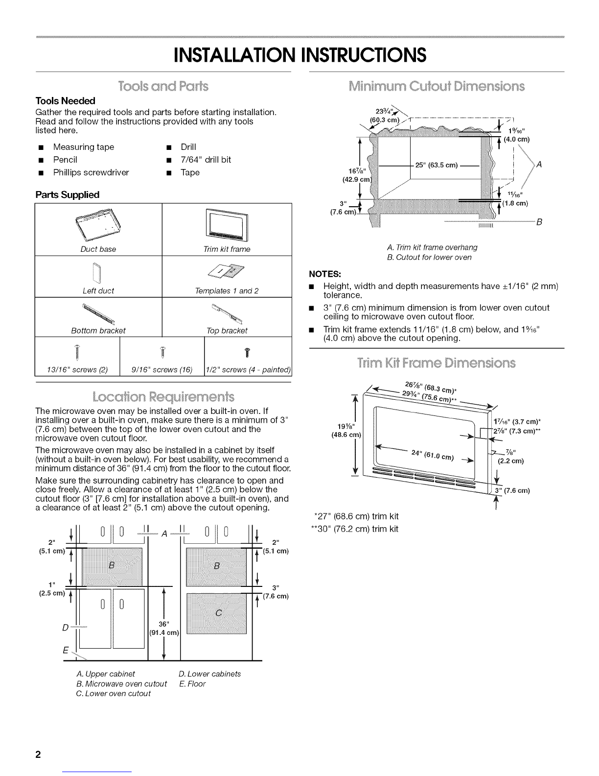
4. Installthe3/16"screw,andleave1/8"(3.2mm)to3/16"
(4.7mm)protrudingfromthecutoutfloor.
A__
B........................,_ _ W' (3.2ram)(rain)
3As" (4.7 ram) (max)
A.3/16" screw
B.Cutout floor
5. Slide microwave oven partway into cutout opening.
NOTE: If Template 2 is missing or unusable, measure straight
up from upper end holes on bottom bracket and mark the
new holes at 121_s'' (32.9 cm) and 1521/32'' (39.8 cm). Make
sure the bottom bracket end holes and the new holes on each
side are plumb. @©
(32.9 cm) |
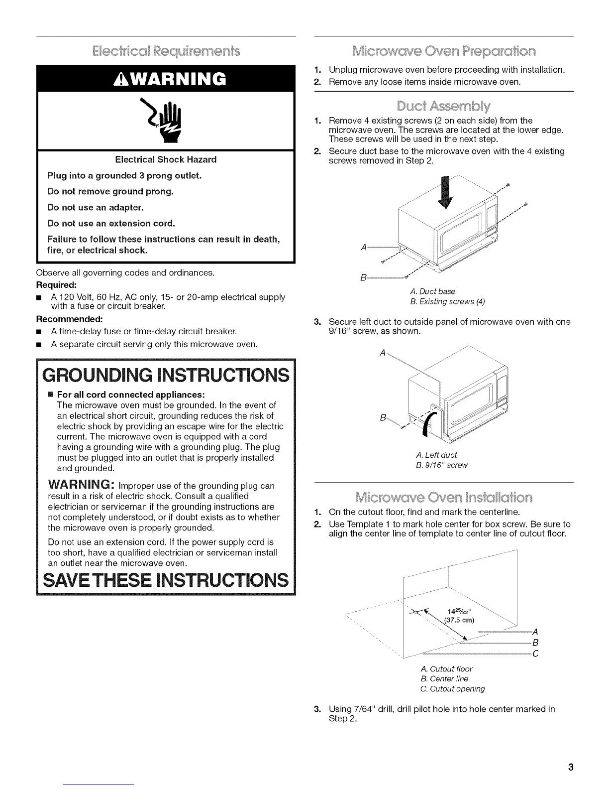
Electrical Shock Hazard
Plug into a grounded 3 prong outlet.
Do not remove ground prong.
Do not use an adapter.
Do not use an extension cord.
Failure to folow these instructions can result in death,
fire, or electrical shock.
6. Plug in microwave oven.
7. Make sure microwave oven is centered in the opening, and
slide it into place, engaging the 3/16" screw and duct base.
1. Align bottom bracket to duct base, and mark 7 mounting
holes of bottom bracket, as shown.
30" (76.2 cm)
27" (68.6 cm)
2.
3.
4.
Using 7/64" drill, drill pilot holes into the cabinet through holes
marked in Step 1.
Install bottom bracket to cabinet using seven 9/16" screws.
Position Template 2 over cabinet so that its reference holes (A)
(for 27" [68.6 cm] installation) or (B) (for 30" [76.2 cm]
installation) are over the upper end mounting holes of the
bottom bracket, as shown in following illustration. Tape the
template in place, then mark through holes (D) for 27"
(68.6 cm) installation, or through holes (C) for 30" (76.2 cm)
installation.
W10308503A
SP PN W10308627A
@2010
All rights reserved.
5. Using 7/64" drill, drill pilot holes into the cabinet through holes
marked in Step 4, then remove template.
6. Position top bracket over pilot holes drilled in Step 5, then
secure with four 9/16" screws. (Illustration in this step shows
30" [76.2 cm] installation.)
c_ .................... A
................... S
...................... C
[--q
A. Top bracket C. Cutout opening
B. Cabinet D. Bottom bracket
1.
2.
In IIYAm Kl
Position trim kit frame against the top and bottom brackets.
Make sure the trim kit frame makes contact with the cabinet.
Open microwave oven door, and secure trim kit frame using
4 painted 1/2" screws.
A
A. Trimkit frame
B. Microwave oven door (open)
C.Painted 1/2" screws (4)
Installation is now complete. Replace any loose items that have
been removed from microwave oven cavity.
Save these Installation Instructions for future reference.
DE68-03169C
4/10
Printed in Malaysia


M Service manual")