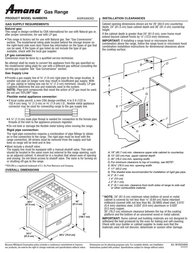
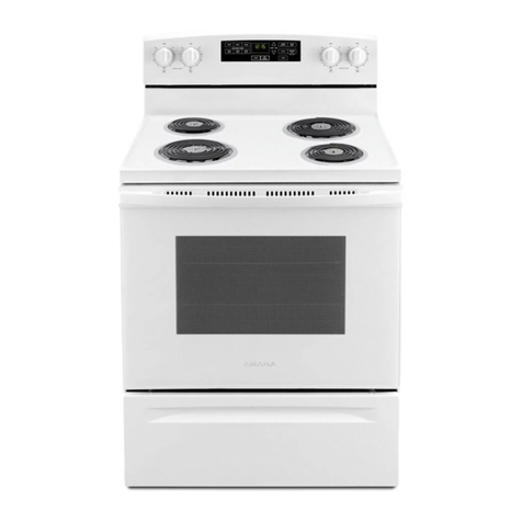
Amana rs2310004-aro3100 Assembly instructions

Service
Thismanualistobeusedbyqualifiedappliance
techniciansonly.Amanadoesnotassumeany
responsibilityforpropertydamageorpersonal
injuryforimproperserviceproceduresdoneby
anunqualifiedperson. RS2310004
Revision 1
September 1999
Manual Clean
Gas Ranges
Base manual covers general information
on Manual Clean Gas Ranges.
Refer to individual Technical Sheets
for information on specific models.

RS2310004 Rev. 1 2
Table of Contents
Important Information .................................................. 4
Introduction
General Information ................................................ 5
Model Identification and Ordering
Replacement Parts.................................................. 5
Amana Cooking Products Nomenclature................ 5
Safety Information
Safety Practices for Servicer .................................. 7
Servicing ................................................................. 7
Receiving Oven ...................................................... 7
Using the Oven ....................................................... 8
Baking, Broiling, and Roasting................................ 8
Connecting Range to Gas....................................... 8
Electrical Requirements .......................................... 9
Extension Cord........................................................ 9
Grounding................................................................ 9
Product Safety Devices ........................................ 10
Installation Instructions Open Burner
Packing Material ................................................... 11
Range Location ..................................................... 11
Cabinet Opening ................................................... 11
Minimum Clearances to Combustible Surface ..... 11
Special Countertop Conditions ............................. 12
Gas Connection Requirements ............................. 12
Gas Supply Location ............................................. 12
Gas Supply Pressure ............................................ 12
Pressure Regulator Location................................. 12
Converting for Use with Natural Gas or
Propane Gas ......................................................... 13
Anti-tip Bracket Installation ................................... 15
Gas Connection .................................................... 16
Testing for Gas Leaks ........................................... 16
Seal Openings....................................................... 17
Place Range.......................................................... 17
Removal and Replacement of Range................... 17
Igniting and Adjusting Top Burner Pilot Flame ..... 17
Test and Adjusting Surface Burner Flame............ 17
Remove Shipping Screws..................................... 18
Place Rangetop and Grates.................................. 18
Ignite Oven Burner Pilot ....................................... 18
Test and Adjust Oven Burner Flame .................... 18
Installation Instructions Sealed Burner
Packing Material ................................................... 19
Range Location ..................................................... 19
Cabinet Opening ................................................... 19
Minimum Clearances to Combustible Surface ..... 19
Special Countertop Conditions ............................. 20
Electrical Connection Requirements..................... 20
Electrical Connection Clearance........................... 20
Gas Connection Requirements ............................. 20
Gas Supply Location ............................................. 21
Gas Supply Pressure ............................................ 21
Pressure Regulator Location................................. 21
Converting for Use with Natural Gas or
Propane Gas ......................................................... 22
Anti-tip Bracket Installation ................................... 24
Gas Connection .................................................... 25
Testing for Gas Leaks ........................................... 26
Seal Openings....................................................... 26
Place Range.......................................................... 26
Removal and Replacement of Range................... 26
Place Grates and Burner Caps ............................. 26
Test and Adjusting Surface Burner Flame............ 27
Test and Adjust Oven Burner Flame .................... 27
General Information
Operating Surface Burners ................................... 28
Operating Surface Burner during a Power Failure 28
Cooking Utensils ................................................... 29
Prepare to Bake .................................................... 30
Baking ................................................................... 30
Adjusting Factory Set Baking Temperature.......... 31
Prepare for Broiling ............................................... 31
General Care and Cleaning
Removing Oven Door ........................................... 32
Remove Grid, Pan, and Rack ............................... 32
Removing Oven Bottom ....................................... 32
Open Burner Care and Cleaning
Removing Rangetop and Grates .......................... 33
Removing Surface Burners................................... 33
Cleaning Surface Burners ..................................... 34
Sealed Burner Care and Cleaning
Place Grates and Burner Caps ............................. 36

3 RS2310004 Rev. 1
Testing Procedures
Oven with Constant Burning Pilot ......................... 38
Oven with Pilot Spark Ignitor ................................ 38
Top Burners with Constant Burning Pilots ............ 39
Top Burners with Spark Ignitor ............................. 39
Oven System–Pilot Ignition .................................. 40
Oven Pilot ............................................................. 40
Safety Valve.......................................................... 40
Oven Thermostat .................................................. 40
Spark Module 4 + 1 and 2 + 1 .............................. 40
Top Burner Spark Ignitors ..................................... 41
Thermostat Spark Switch and
Spark Switch Valve Test ....................................... 41
Oven Light Switch ................................................. 42
Troubleshooting Procedures
Pilot Ignition Models.............................................. 43
Non–Sealed Top Burners...................................... 45
Sealed Top Burners .............................................. 46
Bake and Broil Burners ......................................... 47
Table of Contents Disassembly Procedures
Moving and Replacing Range............................... 48
Open Burner Maintop............................................ 48
Sealed Burner Maintop ......................................... 48
Control Panel ........................................................ 48
Surface Valve and Spark Switch .......................... 48
Backguard ............................................................. 48
Open Burner.......................................................... 48
Sealed Burner ....................................................... 48
Oven Burner Ignitor............................................... 48
Oven Burner.......................................................... 48
Safety Valve.......................................................... 49
Top Burner Venturi................................................ 49
Pressure Regulator ............................................... 49
Manifold................................................................. 49
Oven Thermostat .................................................. 49
Oven Light Bulb/Oven Light Socket ..................... 49
Oven Liner Removal ............................................. 49
Oven Door............................................................. 49
Door Disassembly (solid door) .............................. 50
Door Gasket (solid door) ....................................... 50
Door Disassembly (frameless) .............................. 50
Oven Door Hinge .................................................. 50
Side Panel Removal ............................................. 50
Power Cord ........................................................... 50
Appendix A
Clock and Timer.................................................. A–2
Appendix B
Clock and Timer...................................................B-2

RS2310004 Rev. 1 4
Pride and workmanship go into every product to provide our customers with quality products. It is possible,
however, that during its lifetime a product may require service. Products should be serviced only by a qualified
service technician who is familiar with the safety procedures required in the repair and who is equipped with the
proper tools, parts, testing instruments and the appropriate service manual. REVIEW ALL SERVICE
INFORMATION IN THE APPROPRIATE SERVICE MANUAL BEFORE BEGINNING REPAIRS.
Important Notices for Consumers and Servicers
!
WARNING
To avoid risk of serious injury or death, repairs should not be attempted by an unauthorized personal, dangerous
conditions (such as exposure to electrical shock) may result.
CAUTION
!
Amana will not be responsible for any injury or property damage from improper service procedures. If performing
service on your own product, assume responsibility for any personal injury or property damage which may result.
To locate an authorized servicer, consult your telephone book or dealer from whom you purchased this product.
For further assistance, contact: 1 (800) 628-5782 first, if no answer call number listed below.
CONSUMER AFFAIRS DEPT. OR 1 (800) 843-0304
AMANA APPLIANCES CALL
AMANA, IOWA 52204
If outside the United States contact:
AMANA
ATTN: CONSUMER AFFAIRS DEPT
AMANA, IOWA 52204, USA
Telephone: (319) 622-5511
Facsimile: (319) 622-2180
TELEX: 4330076 AMANA
CABLE: "AMANA", AMANA, IOWA, USA
Recognize Safety Symbols, Words, and Labels
DANGER
!
DANGER - Immediate hazards which WILL result in severe personal injury or death.
WARNING
!
WARNING - Hazards or unsafe practices which COULD result in severe personal injury or death.
CAUTION
!
CAUTION - Hazards or unsafe practices which COULD result in minor personal injury or product or property
damage.
Important Information

5 RS2310004 Rev.1
Model Identification and Ordering
Replacement Parts
Unit’smodel andmanufacturingnumbers arerecorded on
its rating label. Rating label is located on the storage
door frame. It can be seen by opening the storage door.
Beforeordering parts,write downthe correctmodel and
manufacturingnumbers fromratinglabel. Thisavoids
incorrect shipments and delays. Please refer to parts
catalogwhen orderingreplacement parts.
General Information
Thismanual providesbasic instructionsand suggestions
forhandling, installingand servicingAmana gasranges.
Thedirections, information,and warningsin thismanual
aredeveloped fromexperience with,andcareful testingof
the product. If the unit is installed according to this
manual, it will operate properly and will require minimal
servicing.A unitin properoperating orderensures the
consumerall thebenefits providedby clean,modern gas
cooking.
Thismanual containsbasic informationneeded by
authorized Amana service technicians to install and
serviceAmana gasranges.There maybe,however,
someparts whichneed furtherexplanation.Refer to
individualtechnical sheetsor Amanamaintains atoll-free
technical support line to answer questions from
authorizedservice technicians.
Thenumber is1-800-AMANA99.
Amana Cooking Products Nomenclature
Introduction
Brand Product Fuel/Type Configuration Convection Width/Cleaning Feature
Level Additional
Feature Series Color
A
=Amana
C=Caloric
N=Int`l
Z
=Canadian
R=Ran
g
e G=Gas Sealed Burner
O=Gas Open Burner
E=Electric
R=Rou
g
h Top Electric
T
=Radiant Electric
H=Halo
g
enElectric
_
=Free-Standin
g
S=Slide-In
D=Downdraft
_
=No Convection
C=Convection 1=20ª
Manual(Dl)
2
=24ª
Manual(Dl)
3=30ªManual(Dl)
5=30ª
Manual(Fl)
6=30ª
Electric S/C
7=30ªGas S/C
8=30ª
Convection
1=Least
2=
3=
4=
5=
6=
7=
8=
9=Most
5= Slide-In 0 E=Ebon
y
K=Chrome Top
L=Almond
(
Blk Door
)
W
=White
(
Blk Door
)
LL=Almond/Almond
S
S=Stainless
W
W=White/White

RS2310004 Rev.1 6
As with all appliances, there are certain rules to follow for
safeoperation. Verifyeveryone whooperatesoven is
familiar with the operations and with these precautions.
Use appliance only for its intended purpose as described.
Pay close attention to the safety sections of this manual.
Recognize the safety section by looking for the symbol
or the word safety.
Recognize this symbol as a safety precaution.
!
WARNING
!
If the information in this manual is not followed exactly,
a fire or explosion may result causing property
damage,personal injuryordeath.
Donot storeoruse gasolineor otherflammablevapors
and liquids in the vicinity of this or any other appliance.
WHAT TO DO IF YOU SMELL GAS
• Extinguish any open flame.
• Do not try to light any appliance.
• Do not touch any electrical switch; do not use any
phonein yourbuilding.
• Immediatelycall yourgas supplierfrom aneighbor’s
phone. Follow the gas supplier’s instructions.
• If you cannot reach your gas supplier, call fire
department.
Installationand servicemustbe performedbyan
authorizedinstaller,service agencyorgas supplier.
WARNING
!
To avoid risk of electrical shock, property damage,
personalinjury, ordeath,verify wiringis correct,if
componentswere replaced.Verify properandcomplete
operationof unitafterservicing.
WARNING
!
This gas appliance contains or produces a chemical or
chemicals which are known to the state of California to
causecancer,birth defects,orother reproductiveharm.
To reduce the risk from substances in the fuel or from
fuel combustion make sure this appliance is installed,
operatedand maintainedaccordingto theinstructions
in this manual.
Due to the nature of cooking, fires can occur as a
resultof overcookingorexcessive grease.Althougha
fire is unlikely, if one occurs proceed as follows:
Oven Fires
1. Donotopen theovendoor.
2. Turn all controls to OFF.
3. As an added precaution turn off the electricity at
the main circuit breaker or fuse box and the gas
atthe mainsupplyvalve.
4. Allow the food or grease to burn itself out in the
oven.
If smoke or fire persist call the local fire department.
Toavoid theriskof propertydamageor personalinjury
donot obstructthe flowofcombustion orventilation air
tothe oven.
To avoid the risk of electrical shock, serious personal
injuryor death:Makesure youroven hasbeenproperly
groundedand alwaysdisconnect theelectricalsupply
beforeservicing thisunit.
NOTE: The maximum gas supply pressure for these
models must not exceed 14 inches W.C.P.
Safety Information

7 RS2310004 Rev.1
Safety Practices for Servicer
Safeand satisfactoryoperation ofgas rangesdepends
uponits designand properinstallation. However,there is
one more area of safety to be considered:
Servicing
Listedbelow aresome generalprecautions andsafety
practices which should be followed in order to protect the
servicetechnician andconsumer duringserviceand after
servicehas beencompleted.
1. Gas smell—Extinguish any and all open flames and
openwindows.
2. Turngasoff—Service rangewithgas turnedoffunless
testing requires it.
3. Checkingfor gasleaks—Nevercheck forleaks with
any kind of open flame. Soap and water solution
should be used for this purpose. Apply solution to
suspectedarea andwatch forair bubbleswhich
indicates a leak. Correct leaks by tightening fittings,
screws,connections, applyingapprovedcompound,
orinstalling newparts.
4. Usinglights—Usea handflashlight whenservicing
ranges or checking for gas leaks. Electric switches
shouldnot beoperated whereleaks aresuspected.
This will avoid creating arcing or sparks which could
ignite the gas. If electric lights are already turned on,
they should not be turned off.
5. Donotsmoke—Never smokewhile servicinggas
ranges,especially whenworking onpiping that
contains or has contained gas.
6. Checkrangewhen serviceis completed—After
servicing, make visual checks on electrical
connection, and check for gas leaks. Inform
consumerof theconditionof rangebeforeleaving.
7. Adhere to all local regulations and codes when
performingservice.
Receiving Oven
• Installerneeds toshow consumerlocation ofthe range
gasshut-off valveand howto shutit off.
• Authorized servicer must install the range, in
accordancewith theInstallation Instructions.
Adjustmentsand serviceshould beperformed onlyby
authorizedservicer.
• Plug range into a 120–volt grounded outlet only. Do not
removeround groundingprongfrom theplug.If indoubt
about grounding of the home electrical system, it is
consumer'sresponsibility andobligation tohave an
ungroundedoutlet replacedwitha properlygrounded
three-prongoutlet inaccordance withthe National
Electrical Code. Do not use an extension cord with this
appliance.
• Insureall packingmaterials areremovedfrom therange
beforeoperating it,to preventfireor smokedamage
should the packing material ignite.
• Ensure range is correctly adjusted by a qualified
service technician or installer for the type of gas
(Naturalor LP).Some rangescan beconvertedfor use
with Natural or LP gas.
•Withprolonged useof arange,high floortemperatures
could result. Many floor coverings will not be able to
withstandthis kindof use.Never installrange overvinyl
tile or linoleum that cannot withstand high
temperatures.Never installrangedirectly over
carpeting.
Safety Information

RS2310004 Rev.1 8
Using the Oven
• Donot leavechildrenalone orunattended wherea
range is hot or in operation. They could be seriously
burned.
• Do not allow anyone to climb, stand or hang on the
door. Theycould damagetherange andcause severe
personalinjury.
• Wearproper apparel.Loose fittingorhanging garments
shouldnever bewornwhen usingoven.Flammable
material could ignite if brought in contact with flame or
hotoven surfaceswhich maycause severeburns.
• Neveruse rangefor warmingor heating aroom. This
may cause burns, injuries, or a fire.
• Do not use water on grease fires.
• Do not let grease or other flammable materials collect
inor aroundrange.
• Do not repair or replace any part of range unless it is
recommendedin thismanual.
• Use only dry potholders. Moist or damp potholders
used on hot surfaces may result in a burn from steam.
Do not let a potholder touch the flame. Do not use a
towel or a bulky cloth as a potholder.
• Neverleave range unattendedwhilecooking.Boilovers
can cause smoking and may ignite.
• Only certain types of glass/ceramic, earthenware, or
otherglazed utensilsare suitablefor ovenuse.
Unsuitable utensils may break due to sudden
temperaturechange.
• Usecare whenopening ovendoor. Lethot airor steam
escapebefore removingorreplacingfood.
• Donot heatunopened foodcontainersin oven.
Build-up of pressure may cause a container to burst
and result in injury.
• Keeprange ventducts unobstructed.
• Place oven racks in desired location while oven is cool.
If a rack must be moved while oven is hot, use a dry
potholder.
• Do not use aluminum foil to line oven bottom or racks.
Aluminum foil can cause a fire will seriously affect
bakingresults, anddamage toporcelain surface's.
• Donot touchinterior surfacesof ovenduringor
immediately after use. Do not let clothing or other
flammable materials come in contact with bake or broil
burners.
• Otherareas ofthe ovencan becomehot enoughto
causeburns, suchas ventopenings,window, ovendoor
andoven racks.
• To avoid steam burns, do not use a wet sponge or cloth
to wipe up spills on hot cooking area.
• Do not store combustible or flammable materials, such
as,gasoline orother flammablevapors andliquidsnear
orin oven.
• Do not clean oven door gasket located on back of the
door. Gasket is necessary to seal the oven and can be
damagedas aresult ofrubbingor beingmoved.
• Donot drapetowels orany materialson ovendoor
handles. These items may ignite causing a fire.
CAUTION
!
Do not store items of interest to children in cabinets
aboverange. Childrenmayclimb onoventoreach
these items and become seriously injured.
Baking, Broiling, and Roasting
• Donot useoven areaforstorage.
• Standback fromrange whenopening doorof ahot
oven. Hot air or steam can cause burns to hands, face,
and eyes.
• Donot usealuminum foilanywhere inthe oven.This
could result in a fire hazard and damage the range.
• Use only glass cookware appropriate for use in gas
ovens.
• Alwaysremove broilerpanfromoven whenfinished
broiling. Grease left in pan can catch fire if oven is used
withoutremoving greasefromthe broilerpan.
• When broiling, meat that is close to the flame may
ignite. Trim any excess fat to help prevent excessive
flare-ups.
• Make sure broiler pan is placed correctly to reduce any
possibility of grease fires.
• Should a grease fire occur in the broiler pan, turn off
oven,and keepoven doorclosed untilfire burnsout.
Connecting Range to Gas
Install manualshut-off valve ingas lineforeasy
accessibility outside range. Be aware of the location of
theshut-offvalve.
Safety Information

9 RS2310004 Rev.1
Electrical Requirements
120-volt, 60 Hertz, 15 amp, individual circuit which is
properlygrounded, polarized,and protectedby acircuit
breakeror fuse.
Extension Cord
Due to possible pinching during installation, extension
cords should not be used on products.
Extensioncords willadversely affectthe performanceof
glow bar ignitor and spark system.
Grounding
NOTE: Thisappliance mustbe properlygrounded,for
personalsafety.
Power cord on this appliance is equipped with a three-
pronggrounding plug.Thismatches standardthree-prong
groundingwall receptacleto preventpossibility ofelectric
shock from this appliance.
Consumershould havewall receptacleandcircuit
checked by qualified electrician to verify receptacle is
properlygrounded.
Wherestandard two-prongwall receptacleis
encountered, it is consumers responsibility and
obligationto haveit replacedwitha properlygrounded
three-prongwall receptacle.
DONOT,UNDER ANY CIRCUMSTANCES, CUT OR
REMOVETHE THIRD (GROUND) PRONGFROM
POWER CORD.
For 15 amp. circuits only. Do not use an adapter on 20
amp. circuit. Where local codes permit, a TEMPORARY
CONNECTIONmay bemadeto properlygroundedtwo-
prong wall receptacle by the use of a UL listed adapter
availableat mosthardware stores.
Larger slot on adapter must be aligned with larger slot in
thewall receptacleto provideproper polarity.
WARNING
!
Attachingadapter groundterminalto wallreceptacle
coverscrew doesnotground applianceunlessthe
cover screw is metal and not insulated, and wall
receptacleis groundedthroughthe housewiring.
Consumershould havecircuitchecked byaqualified
electricianto verifyreceptacleis properlygrounded.
Whendisconnecting powercord fromadapter,always
hold adapter with one hand. If this is not done, adapter
ground terminal is very likely to break with repeated use.
Should this happen, DO NOT USE appliance until a
properground hasbeenestablished.
Neutral Wire
Hot Line
Ground
NOTE: Circuit tester can be use to verify voltage is
present at the outlet, connect one lead to hot
line and the other lead to ground, circuit tester
should light.
Safety Information

RS2310004 Rev.1 10
Product Safety Devices
Safetydevices andfeatures havebeenengineered intothe productto protect consumerand servicer.Safety devices
must never be removed, bypassed, or altered in such a manner as to defeat the purpose for which they were intended.
Listedbelow arevarious safetydevices togetherwith thereason eachdevice isincorporated inthe gasranges.
Pressure Regulator Maintainsproper andsteadygas pressureforoperationof ovencontrols.Regulator
must be set for the type of gas being used Natural or LP. After servicing regulator,
make certain it is set properly before completing service.
Gas Burner Orifices Universalorifices areused onmost valves.They mustbe adjusted orset forthe type
of gas being used Natural
or LP.
Afterservicing avalveororifice verifyitis adjustedproperlybeforecompleting service.
Oven Safety Valve Ovenvalve isdesignedto bea safetyvalve.Twobasic designsare used ingas
ranges.
Hydraulictypevalve
Electrictype valve
Bothtypes aresafety valvesbecausethey areindirectly operatedby the oven
thermostat, which controls a pilot flame or electric ignitor, to open and close the oven
valve.
LatchAssembly Locks the door during self-cleaning cycle. Prevents possible injury to consumer by
preventingdoor openingathigh temperatureswhereignition ofsoilcould takeplace
with the inrush of air.
Grounded Oven Frame Groundprong onpower cordisconnected tothe frame, usuallya greenleadfastened
by a screw. In addition, any part or component capable of conducting an electric
current is grounded by its mounting.
If any ground wire, screw, strap, nut, etc. is removed for service, or any reason, it
mustbe reconnectedto itsoriginalposition withoriginal fastener beforethe appliance
is put into operation again.
Failure to do so can create a possible shock hazard.
Safety Information

11 RS2310004 Rev. 1
Installation Instructions Open Burner
Packing Material
Remove protective packing material from range. Tape
residue can be cleaned with a soft cloth and alcohol.
Range Location
Choose a location based on following factors.
• Drafts caused by home heating and air conditioning
and open doors or windows can disrupt ventilation air
pattern. Range should not be installed near windows
or doors.
• Make sure there is adequate space for proper
installation.
• Carefully read all instructions before beginning
installation.
Cabinet Opening
WARNING
!
To avoid risk of burns or fire by reaching over
elements, cabinet storage space located above range
should be avoided. If cabinet storage is provided,
install a range hood that projects horizontally a
minimum of 5 inches beyond the cabinet bottom to
reduce the risk.
Range should extend approximately 2 inches from
cabinet front to oven door handle. Use dimensions in
figure below and shown in “Special Countertop
Conditions” section to prepare cabinet opening.
A
C
B
D
E
A—301/8 to 30¼ inches
B—36 inches standard
C—35 inches standard
D—24 inches standard
E—25 inches standard
Minimum Clearances to Combustible
Surfaces
• Minimum clearance to rear wall is 0 inches.
• Minimum clearance to a vertical right or left side wall
extending above cooking surface is 3 inches.
• Minimum clearance to countertop/cabinet on each
side is 0 inches.
• Minimum of 30 inches between top of cooking surface
and bottom of an unprotected wood or metal cabinet.
• 24 inches between cooking surface and protected
wood or metal cabinet above range. Cabinet bottom
must be protected by at least ¼ inch thick millboard
with not less than No. 28 MSG sheet steel, .015 inch
thick stainless steel, .024 inch thick aluminum, or .020
inch thick copper.
A
B
C
D
EF
G
H
J
A—30 inches minimum
B— 0 inches
C—30 inches unprotected/24 inches protected minimum
D—13 inches
E—0 inches
F—25 inches maximum
G—36 inches maximum
H—3 inches minimum (Both sides of range)
J—18 inches minimum

RS2310004 Rev. 1 12
Installation Instructions Open Burner
Special Countertop Conditions
Countertops such as ceramic tile tops cause cabinet
and countertop to be higher than 36 inches. Follow
instructions below when countertop is higher than 36
inches.
1. Raise leveling legs to maximum level.
2. Measure from floor to side trim. If measurement is
less than height of countertop, floor must be
shimmed.
3. Shim floor using a piece of plywood same size as
range opening. Secure plywood to floor. Plywood
must be as secure as original flooring.
4. Install anti-tip bracket(s) and slide range into place.
Gas Connection Requirements
Before connecting this appliance to the gas supply
piping system, confirm installation meets the
requirements of local codes, or in the absence of local
codes, with the National Fuel Gas Code,
ANSI Z223.1-Latest Edition.
The installation of appliances designed for
manufactured (mobile) home installation must conform
with Manufactured Home Construction and Safety
Standard, Title 24 CFR, Part 3280, or when such
standard is not applicable, the Standard for
Manufactured Home Installation,
ANSI225.1/NFPA 501A-Latest Edition, and with local
codes where applicable.
Gas Supply Location
Gas supply must be located in the area shown.
A
BCD
E
A—26 inches

B—20 inches
C—2¼ inches
D—4 inches
E—6 inches
Gas Supply Pressure
CAUTION
!
To avoid property damage, maximum gas supply
pressure must not exceed 14" WCP.
• Appliance and individual shutoff valve must be
disconnected from the gas supply piping system
during any pressure testing of that system at test
pressures in excess of ½ psig (3.5kPa) (14" WCP).
• Appliance must be isolated from gas supply piping
system by closing manual shutoff valve during any
pressure testing of the gas supply piping system at
test pressures equal to or less than ½ psig (3.5kPa)
(14" WCP).
• Gas supply pressure for checking regulator setting
must be at least 1" WCP above manifold pressure
shown on rating label.
Pressure Regulator Location
Remove rear cover to expose pressure regulator.

13 RS2310004 Rev. 1
Installation Instructions Open Burner
Converting for Use with Natural Gas or
Propane Gas
This range arrives from factory adjusted for use with
natural gas. If using LP/propane gas is desired, range
must be converted. See “Type 1” or “Type 2” regulator.
WARNING
!
To avoid electric shock that can cause personal injury
or death, disconnect main electrical supply to range
before servicing.
Converting Type 1 Pressure Regulator for Use with
LP/ Propane
1. Remove pressure regulator cap with a wrench.
2. Remove plastic insert from pressure regulator cap.
• Plastic insert fits tightly in cap.
3. Reverse plastic insert and carefully push plastic
insert firmly into hole in pressure regulator cap.
• Cap must show “LPG10” or “LP10”.
4. Place pressure regulator cap on pressure regulator
and tighten.
• Insert should not disturb spring in body of
regulator.
A
B
C
A—Cap
B—Plastic Insert (LP setting)
C—Spring Location
Converting Type 2 Pressure Regulator for Use with
LP/Propane
1. Remove pressure regulator cap with a wrench.
2. Reverse pressure regulator cap.
• Cap must show “LP”.
3. Place pressure regulator cap on pressure regulator
and tighten.
A
LP
A—Cap
Converting Surface Burners for Use with
LP\Propane
1. Lift the rangetop off of the range.
• A peg on each side of rangetop holds rangetop in
place.
2. Turn all 4 orifice hoods (tighten) counterclockwise
when facing front of range 1½ to 2 turns or until
snug.
• Use ½-inch wrench.
• Do not over tighten orifice hoods. If orifice hoods
are over tightened, gas supply can be cutoff or
orifice hood threads can strip.

RS2310004 Rev. 1 14
Installation Instructions Open Burner
A
B
Open Fully
A—Orifice Hood
B—Air Shutter
3. Pull all 4 air shutters fully open.
Converting Oven Burner for Use with LP\Propane
1. Open broiler door and remove broiler rack, pan, and
grid.
2. Through rectangular hole on rear of broiler cavity,
turn orifice hood (tighten), clockwise when facing
front of range, 1½ to 2 turns or until snug.
• Do not overtighten orifice hoods. Orifice hoods
can strip.
A
B
C
Open
Fully
A—Air Shutter Screw
B—Orifice Hood
C—Air Shutter
3. Open air shutter fully.
Converting Oven Thermostat for Use with
LP\Propane
1. Remove all (5) control knobs from range.
• Exposes 2 screws on burner control panel.
2. Remove 2 screws from burner control panel.
• Panel drops slightly after screws are removed.
3. Grasp bottom of burner control panel, gently lift and
pull out panel until clear of burner valve stems.
• After burner control panel clears valve stems,
continue to roll panel until free from range. Set
aside.
AB
C
D
A—Burner Control Knob
B—Pivot Point
C—Burner Control Panel
D—Screw
4. Turn the selector screw on oven thermostat so the
pointer is towards “LP”.
5. Reverse steps 1–3 to replace control panel and
knobs.
Selector Screw
LP N
OFF
LP N
OFF
LP N
OFF

15 RS2310004 Rev. 1
Installation Instructions Open Burner
Converting Type 1 Pressure Regulator for Use with
Natural Gas
1. Remove pressure regulator cap with a wrench.
2. Remove plastic insert from pressure regulator cap.
• Plastic insert fits tightly in cap.
3. Reverse plastic insert and carefully push plastic
insert firmly into hole in pressure regulator cap.
• Insert must show “NAT” or be blank.
4. Place pressure regulator cap on pressure regulator
and tighten.
• Insert should not disturb spring in body of
regulator.
Converting Type 2 Pressure Regulator for Use with
Natural Gas
1. Remove pressure regulator cap with a wrench.
2. Reverse pressure regulator cap.
• Insert shows “NAT” or is blank.
3. Place pressure regulator cap on pressure regulator
and tighten.
Converting Surface Burners for Use with
Natural Gas
1. Lift the rangetop off of the range.
2. Turn all 4 orifice hoods (loosen) clockwise when
facing front of range 1½ to 2 turns.
• Use ½-inch crescent wrench.
3. Close all 4 air shutters to approximately 1/8inch.
Converting Oven Burner for Use with Natural Gas
1. Remove broiler drawer.
2. Turn orifice hood counterclockwise (loosen) 2 full
turns.
3. Close air shutter to approximately 3/8inch.
4. Replace broiler door.
Converting Oven Thermostat for Use with Natural
Gas
1. Remove 4 burner control knobs from range.
• Exposes 2 screws on burner control panel.
2. Remove 2 screws from burner control panel.
• Panel drops slightly after screws are removed.
3. Grasp bottom of burner control panel, gently lift and
pull out panel until clear of burner valve stems.
• After burner control panel clears valve stems,
continue to roll panel until free from range. Set
aside.
4. Turn the selector screw so the pointer is towards “N”.
5. Reverse steps 1-3 to replace control panel and
knobs.
Anti-tip Bracket Installation
To reduce risk of range tipping, secure range with a
properly installed anti-tip bracket.
1. Measure 31/2inches from back wall on right and left
side of cabinet cutout. Mark measurements on floor
and draw a straight line connecting marks.
2. Position anti-tip bracket.
• If range is installed beside cabinet(s), place anti-
tip bracket with back edge on line drawn on floor
and side of bracket against cabinet.
• If range is not installed beside cabinet(s), position
range where it will be installed. Draw a line along
side of range on floor from front to back. Remove
range. Place anti-tip bracket with back edge over
line drawn 31/2inches from back wall and side of
bracket over line drawn along side of range on
floor.
• Anti-tip bracket can be installed on either right or
left side.
or
3 1/2"
3. Mark 2 hole locations in anti-tip bracket.
4. Drill 2 holes.
• If drilling into wood, use a 3/32 inch drill bit.
• If drilling into concrete, use a 3/16 inch masonry
drill bit and insert plastic anchors.
5. Secure bracket to floor using screws supplied.
6. After range is slide into position, verify the range
leveling leg has engaged anti-tip bracket.

RS2310004 Rev. 1 16
Installation Instructions Open Burner
Verifying anti-tip bracket position
1. After range is in place, open broiler door and remove
broiler rack, pan, and grid.
2. Remove screws in front of broiler area on side of
range that anti-tip bracket is installed.
3. Remove panel and look towards back of oven and
check anti-tip bracket has engaged bracket.
4. Reinstall panel after checking anti-tip bracket.
Remove
Screws
Remove
Panel
Gas Connection
Connect gas supply to regulator using hard pipe or
flexible connector (Check local codes). Pressure
regulator supplied with this appliance has a ½ inch NPT
female connection.
• A manual shutoff, not supplied with range, must be
installed in an accessible location outside of range.
• Use joint compound that is resistant to action of
propane gas on all male pipe threads.
• Use supplied pressure regulator only.
• Do not overtighten gas fitting when attaching to
pressure regulator. Overtightening may crack
regulator.
• Support pressure regulator with wrench when
installing gas fitting.
WARNING
!
To avoid property damage or personal injury, only use
a new flexible connector that is AGA/CGA design
certified.
• Do not use an old connector.
• Do not reuse a connector after moving appliance.
• Refer to National Fuel Gas Code or local codes for
supply pipe size requirements, to assure sufficient gas
is supplied to the unit.
Testing for Gas Leaks
After final gas connection is made, turn on manual gas
valve and test all connections in gas supply piping and
range for gas leaks.
WARNING
!
To avoid property damage or serious personal injury,
never use a lighted match to test for gas leaks.
1. Place soap suds on connections.
• Bubbles appear if leak is present.
2. If bubbles appear, shut off gas supply valve.
3. Tighten joint if leak is at factory fitting.
• If leak is not at factory fitting, unscrew, apply more
joint compound, and tighten to correct leak.
4. Retest connection for leak after tightening.
• Retest any connections that were disturbed.

17 RS2310004 Rev. 1
Installation Instructions Open Burner
Seal Openings
Openings in wall behind the range or on floor under
range must be sealed before sliding range into position.
Place Range
1. Slide range into place.
• Leveling legs must be extended out ¼ inch to
engage anti-tip bracket.
2. Carefully level range using legs provided. Range
must be level to cook and bake uniformly.
• Place a level on top oven rack or on top of range
when leveling.
Removal and Replacement of Range
1. Turn off gas valve and disconnect gas supply.
2. Remove range and place aside.
3. Remove anti-tip bracket and reinstall anti-tip bracket
into new location using instructions in this manual.
4. To reinstall range, follow instructions in “Installation”
section of this manual.
• Do not reuse a flexible connector after moving
appliance.
Igniting and Adjusting Top Burner Pilot
Flame
1. Check that all burner control knobs are in the OFF
position.
2. Remove grates and lift off rangetop.
3. Ignite both top burner pilots with match.
• Pilot flame should be 1/4to 3/8inch high and
centered in the pilot housing.
Ignite Pilot
4. If necessary, adjust pilot flame size. Remove
rangetop if necessary.
• Tighten or loosen pilot adjustment screw, located
behind oven temperature knob, until flame is 1/4to
3/8inch high and centered in pilot housing.
• If flame is too high, black marks (carbon) will form
on the bottom of the rangetop.
Pilot Adjusment
Screw
Test and Adjusting Surface Burner Flame
Turn on burner. See “Operating Surface Burners”
section for burner operating instructions. Surface burner
should ignite within 4 seconds. Properly adjusted
surface burner flames are clean and blue with a distinct
inner cone approximately ¼ inch to ½ inch long. Some
yellow flame is normal when burning LP/Propane.
1/4 to 1/2 inch
Remove rangetop to adjust air shutters. If burner flame
is blowing or noisy, reduce airflow to burner (close
shutter). If burner flame does not hold its shape,
increase airflow to burner (open shutter). Repeat test if
necessary.
A
Open
Close
A—Air Shutter

RS2310004 Rev. 1 18
Installation Instructions Open Burner
Remove Shipping Screws
Remove shipping screws.
Shipping Screws
Place Rangetop and Grates
Replace rangetop and place grates over burners. A peg
on each side of range holds rangetop in place.
Ignite Oven Burner Pilot
1. Open broiler door and remove broiler pan, grid, and
rack.
2. In rear of broiler cavity, hold a match near pilot as
shown in illustration.
3. Quickly remove hand and match when pilot ignites.
Test and Adjust Oven Burner Flame
Turn on oven burner. See “Baking” section for oven
burner operating instructions. Properly adjusted oven
burner flames are blue with a distinct deep blue inner
cone approximately ½ inch long. When using natural
gas, flame should not have any yellow flame when
burning. Some yellow flame when burning LP\propane
gas is normal.
Flame should not be visible in the oven cavity when
burning and should not extend into the oven cavity
beyond the removable oven bottom.
• If burner flame is blowing or noisy, reduce airflow to
burner.
• If burner flame is yellow and does not hold its shape,
increase airflow to burner.
1. Check that oven temperature knob is in OFF position.
2. Open broiler door and remove broiler pan, grid, and
rack.
3. Through rectangular hole in rear of broiler cavity,
loosen air shutter lock screw and open or close air
shutter.
• Tighten air shutter lock screw after adjusting.
A
B
Open Close
A—Air Shutter Lock Screw
B—Air Shutter
4. Repeat test if necessary.
5. Replace broiler pan, grid, and rack.

19 RS2310004 Rev. 1
Installation Instructions Sealed Burner
Packing Material
Remove protective packing material from range. Tape
residue can be cleaned with a soft cloth and alcohol.
Range Location
Choose a location based on following factors.
• Drafts caused by home heating and air conditioning
and open doors or windows can disrupt ventilation air
pattern. Range should not be installed near windows
or doors.
• Make sure there is adequate space for proper
installation.
• Carefully read all instructions before beginning
installation.
Cabinet Opening
WARNING
!
To avoid risk of burns or fire by reaching over burners,
cabinet storage space located above range should be
avoided.
Range should extend approximately 2 inches from
cabinet front to oven door handle. Use dimensions in
figure below and shown in
Special Countertop
Conditions
section to prepare cabinet opening.
A
C
B
D
E
A—301/8 to 30¼ inches
B—36 inches standard
C—35 inches standard
D—24 inches standard
E—25 inches standard
Minimum Clearances to Combustible
Surfaces
• Minimum clearance to rear wall is 0 inches.
• Minimum clearance to a vertical right or left side wall
extending above cooking surface is 3 inches.
• Minimum clearance to countertop/cabinet on each
side is 0 inches.
• Minimum of 30 inches between top of cooking
surface and bottom of an unprotected wood or metal
cabinet.
• 24 inches between cooking surface and protected
wood or metal cabinet above range. Cabinet bottom
must be protected by at least ¼ inch thick millboard
with not less than No. 28 MSG sheet steel, .015 inch
thick stainless steel, .024 inch thick aluminum, or
.020 inch thick copper.
A
B
C
D
EF
G
H
J
A—30 inches minimum
B— 0 inches
C—30 inches unprotected/24 inches protected minimum
D—13 inches
E—0 inches
F—25 inches maximum
G—36 inches maximum
H—3 inches minimum (Both sides of range)
J—18 inches minimum

RS2310004 Rev. 1 20
Installation Instructions Sealed Burner
Special Countertop Conditions
Countertops such as ceramic tile tops cause cabinet
and countertop to be higher than 36 inches. Follow
instructions below when countertop is higher than 36
inches.
1. Raise leveling legs to maximum level.
2. Measure from floor to side trim. If measurement is
less than height of countertop floor must be
shimmed.
3. Shim floor using a piece of plywood same size as
range opening. Secure plywood to floor. Plywood
must be as secure as original flooring.
4. Install anti-tip bracket(s) and slide range into place.
Electrical Connection Requirements
WARNING
!
To avoid the risk of serious electrical shock or
property damage, do not cut or remove the third
(ground) prong from the power plug. A 3-wire
grounded conductor system must be used. Relying on
the flexible connector, hard piping or any other part of
the gas supply line as a ground may cause fire,
electrical shock and/or erratic control operation.
Range must be electrically grounded in accordance with
local codes or in the absence of local codes, with the
National Electrical Code, ANSI/NFPA No. 70-Latest
Edition.
In Canada, electrical connections are to made in
accordance with CSA C22.1 Canadian Electrical Code.
All electrical connections are to be made in accordance
with CSA standards Z240.6.1 electrical requirements for
mobile homes.
Use a dedicated 120 volt, 60 hertz, 3-prong receptacle
protected by a 15 amp circuit breaker or time delay fuse.
A qualified electrician should confirm the outlet is
properlygrounded.
If a 2-prong outlet is encountered, range owner must
replace outlet before using range. Do not cut off cord,
use plug adapter or extension cord, or remove
grounding plug.
Electrical Connection Clearance
Electrical connection must be located in the shaded
area shown. Electrical connection must not interfere
with gas connection.
A
BC
D
E
A—21/8 inches (Both sides)
B—19½ inches
C—12 inches
D—20 inches
E—301/4
Gas Connection Requirements
Before connecting this appliance to the gas supply
piping system, confirm installation meets the
requirements of local codes, or in the absence of local
codes, with the National Fuel Gas Code, ANSI Z223.1-
Latest Edition.
When installed in mobile housing, installation is to be in
accordance with CSA standard Z241.1 gas equipped
mobile housing.
The installation of appliances designed for
manufactured (mobile) home installation must conform
with Manufactured Home Construction and Safety
Standard, Title 24 CFR, Part 3280, or when such
standard is not applicable, the Standard for
Manufactured Home Installation, ANSI225.1/NFPA
501A-Latest Edition, or with local codes or the standard
CAN/CSA-z240MH, “Mobile Homes”, and with local
codes where applicable.
The installation of appliances is to be in accordance with
CAN1-B149.1 or B149.2 installation code for gas
burning appliances and equipment and/or local codes.
Part 1 and/or local codes.
Table of contents
Other Amana Range manuals

Amana
Amana ARG7303 User manual

Amana
Amana AGR4422VDD0 User manual

Amana
Amana ACR4303MFB2 User manual

Amana
Amana AEP222VAW0 User manual

Amana
Amana AEP200VA User manual

Amana
Amana Easy Touch Control 800 User manual

Amana
Amana AES1350BAW User manual

Amana
Amana THE BIG OVEN ACF4205A User manual

Amana
Amana ARG7303 Manual

Amana
Amana AER6603SFW User manual

Amana
Amana AGR3311WD User instructions

Amana
Amana ARR629 User manual

Amana
Amana AGG200AAW0 User manual

Amana
Amana ARG3601 Technical document

Amana
Amana ARG3600 Series User manual

Amana
Amana AGS3760BD Parts list manual

Amana
Amana AGR3311WDW0 User manual

Amana
Amana AES5730BA User instructions

Amana
Amana W10196156A User manual

Amana
Amana ELECTRIC RANGE User manual