1.1
1.2
1.3
1.4
1.4.1
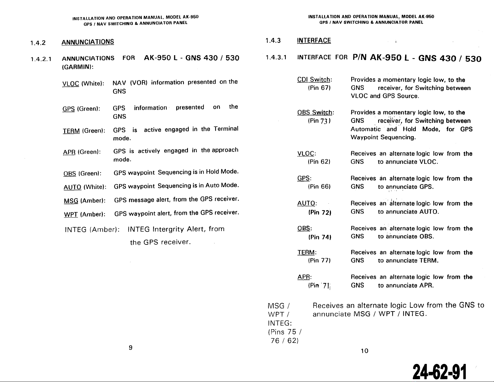
1.4.2
1.4.3
1.
5
1.6
1.7
2.1
2.2
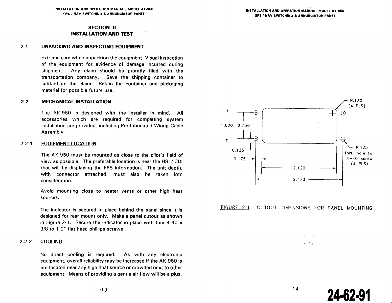
2.2.1
2.2.2
2.2.3
2.2.4
2.2.5
2.3
2.4
2.4.1
2.4.2
INS 1
ALLA
li
UN
ANU
Uf't:ll"
IIUI"
IVI"I"U"L,
"IUUI:L
Hl\
.,;_,v
GPS 1
NAV
SWITCI-IING &
ANNUNCIATOR
PANEL
TABLE OF CONTENTS
Table
of
Contents ···············································
SECTION 1
GENERAL INFORMATION
Scope
................................................................
3
Description ..................................................... .... 3
Technical Characteristics
......................................
6
Front Panel Contrais and Annunciations .................. 8
Contrais
.......................................................
8
Annunciations ......... ...................................... 9
Interface ....................................................... 10
Equipment Limitations ............ .. ............................
11
Major Components ............... ................................
11
Accessories supplied .............. ............ ................ ..
11
SECTION
Il
INSTALLATION
AND
TEST
Unpacking and lnspecting Equipment ...................... 13
Mechanical Installation .............. .................... ........
13
Equipment Location ........................................ 13
Cooling
.........................................................
13
Additional Annunciations ............ ............. .. ...... 15
Additional
Rel
ays ............................................ 15
Rou
ting
of
Ca
bles ........ ................................... 15
Electrical Installation ............................................. 15
Post Installation Test .... ........ .
..
.... .............. .. .........
21
Pre
Installation Tests ... ...... ....
......
.....
......
......
...
21
Operating Instructions .....................................
21
1
3.1
3.2
4.1
4.2
4.3
1.1
2.1
3.1
3.2
3.3
INS 1
ALLA
li
UN
ANU
UPtHA
li
UN
MANUAL,
MUUEl
AK-!IbU
GPS 1
NAV
SWITCHINO
&
ANNUNCIATOR
PANEL
...
,.,
TABLE
OF
CONTENTS CCONT"D)
SECTION
Ill
OPERATION
General
..............................................................
23
Operation
SECTION
IV
WARRANTY
AND
SERVICE
23
Limited
Warranty
.......................................
....
......
25
Repair Service .....................................................
27
Factory Comprehensive Test Service
......................
27
LIST OF FIGURES
Outline Drawing
for
ali Series ................................ 4
Cutout
Dimensions
for
Panel
Mounting
...................
14
Schematic Pino
ut
for
Connecter ..
~.........................
16
E~ectrical
Schematic Diagraîn ................................
18
Wiring Diagram
.......................................
:............ 19
APPENDIX A
Environmental Qualification
form
RTCA 1
D0160C
....
28
2
24-62·91
The document reference is online, please check the correspondence between the online documentation and the printed version.