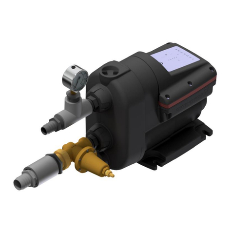
AmeriWater SSV Manual

SSV DISTRIBUTION PUMP
SYSTEM
OPERATION & MAINTENANCE MANUAL
Manufactured With Pride
In The USA
www.ameriwater.com • 800-535-5585
AmeriWater • 3345 Stop 8 Rd. • Dayton, OH 45414
P/N 98-0096
REV A

TABLE OF CONTENTS
1.0 INTRODUCTION..................................................................... 1
2.0 THEORY OF OPERATION..................................................... 1
3.0 INSTALLATION...................................................................... 2
4.0 START-UP.............................................................................. 2
5.0 DAILY MONITORING............................................................. 3
6.0 ADJUSTING THE TIMER....................................................... 4
7.0 SPARE PARTS LIST.............................................................. 5
8.0 PUMP CURVES...................................................................... 6
9.0 SYSTEM DRAWINGS............................................................. 8
10.0TROUBLESHOOTING GUIDE.............................................. 18

98-0096A
1
1.0 INTRODUCTION
The AmeriWater distribution pump takes the water from the storage tank, pumps it through the
distribution loop to the points of use for dialysis and re-circulates water back through the
piping to the storage tank. This provides pressurized water to each dialysis wall box in
addition to re-circulating the water. Re-circulating the water keeps it “fresh” by minimizing
bacteria growth by the constant movement of water.
Please read the Operations Manual before using the system. Contact AmeriWater
Customer Service with any questions at 1-800-535-5585 Monday through Friday 8:00 a.m. to
5:00 p.m. eastern standard time. For after hours emergencies call 1-800-535-5585 and follow
the instructions on the recorded message. Our on-call technician will return your call as soon
as possible.
2.0 THEORY OF OPERATION
When the water is at the minimum level (always controlled by the lowest float switch on the
storage tank), the distribution pump is not allowed to automatically operate through the
distribution controller. When the water level is below the minimum level, the distribution pump
will not operate in “AUTO”, but may be operated in “HAND” (manual operation). The
distribution pump should only be placed in “HAND” to empty the storage tank. It should not be
left unattended during this process. Running the distribution pump for an extended period
without water will result with overheating and damage to the pump.
The distribution pumps are available as a single pump or a dual pump. All distribution pumps
are available in 220V single phase, 208V 3 phase, 230V 3 phase and 460V 3 phase. The
distribution pumps use an SSV pump and have a capability of running at rated volume up to
75 PSI.
The distribution pump controllers have either fuses (for single phase), or overloads (for three
phase) to protect the pumps and wiring from overload damage.
The controllers for the dual distribution pumps have an alternating feature that will allow the
pumps to alternate from #1 pump to #2 pump that is controlled by a timer set at 5 hours.
WARNING: Both pumps need to be in auto mode for normal operation. If one pump is
taken down, ensure that the second pump is set to manual mode. If this is
not done, the controller will attempt to cycle between them. The system
should only be run in manual mode for the length of time it will take to
bring the second pump back on line.
Another AmeriWater standard feature for the dual distribution pump controller is to have an
overload sensor for each pump. If a pump has an overload condition, the controller will
automatically switch to the pump that does not have an overload. This will prevent a possible
water delivery shutdown during the dialysis procedure. An indicator light is on the front panel
of the controller to show which pump has an overload failure.

98-0096A
2
3.0 INSTALLATION
CAUTION: Local plumbing and electrical codes must be observed.
The following guidelines should be met at installation.
1. Customer is to provide properly sized wiring to the distribution pump control enclosure.
2. Place the pump system on firm, level floor and anchor to the floor to prevent movement
from vibration or bumping.
3. Inlet piping and / or hoses from the storage tank to the pump system should be equal to
or greater in diameter than the inlet piping on the pump system.
4. Outlet piping and / or hoses of the pump system should be equal to or greater in
diameter than the outlet piping on the pump system.
5. Locate the pump control on a wall as close to the pump system as possible. When
installing a distribution pump along with an AmeriWater Central Water System, refer to
the Plumbing and Instrumentation Diagram (P&ID) for the best location and where
connections are made.
6. Follow all local plumbing and electrical codes.
7. After guidelines have been met, connect the distribution pump wiring to the motor
contactor located in the control panel (refer to the control wiring diagram provided in
this manual and with the distribution pump control). Connect the three phase or single
phase power source to the Main ON/OFF disconnect switch located inside the control
panel.
CAUTION: For three phase systems, check the rotation of the pump. Turn the main
power disconnect to the on position and observe the rotation of the pump.
When facing the motor end, correct rotation is in the clockwise rotation. If
the rotation is backwards, switch two pump wires on the motor contactor
inside the panel.
4.0 START-UP
1. Open the inlet and outlet valves to the pump and allow the water in the storage tank to
“flood” the inlet of the distribution pump. If the storage tank does not have water in it,
fill it to above the lowest float switch before attempting to use the pump.
2. To prime the pump, close the discharge valve. Remove the vent plug. For 2SV only,
fully unscrew the pin located in the drain plug. Open the suction valve until liquid flows
out of the vent plug opening.
NOTE: Place a loose rag over the open vent port to prevent large amounts of liquid from
being sprayed on the pump and adjacent equipment.

98-0096A
3
3. Close the drain plug pin (2SV only) and open the discharge valve. Install and torque
the vent plug to 15 lbs ft (20 N m). Close the drain plug pin.
4. Verify that the voltage on the pump matches what is indicated on the overload of the
motor starter.
5. Once the power source has been connected, check the rotation of the pump. Turn the
disconnect to the ON position. Jog each pump by momentarily turning the pump power
switch to the HAND position. A second person may be needed to see which way the
motor armature is turning just before it coasts to a stop. If the rotation is backwards,
switch any two of the three non-ground pump wires on the motor contactor inside the
panel.
6. After rotation has been verified, turn the switches on the controller to HAND. Allow
water flow to re-circulate through the loop and back in to the storage tank for a few
minutes. Water flow can be verified by observing the flow meter on the return header
of the storage tank. If this is a dual pump system, place pump #1 into HAND mode to
ensure that there is adequate flow through the system at the holding tank flow meter.
Once verified, repeat this for pump #2.
7. Place the system into auto mode to verify that the low level cut off switch operates
correctly. For a dual pump system, this will need to be done for each pump.
8. For the dual pump system only, the timer will need to be verified. This is accomplished
by setting the timer to its minimum value and ensuring that the system is alternating
between the pumps. See page 4 for details on adjusting the set-point.
9. The inlet and outlet valves are provided to allow for isolation of each pump if
maintenance is needed. During operation, leave all of the inlet and outlet valves open.
10.When performing a start-up of your distribution pump that is connected to a central
system storage tank, adjust the pressure relief valve on the storage tank header so that
the pressure gage at the pump is no higher than 75 PSI. Refer to the manual that was
provided with your storage tank system for proper adjustments. Pump curves have
been provided on pages 6 & 7.
5.0 DAILY MONITORING
AmeriWater recommends that the distribution pump assembly be checked at least once per
day to ensure that the pump is building pressure. To do this, read the pressure on the first
gage after the booster pump while water is flowing. This value should be recorded in the daily
logbook. During this check, listen to the distribution pump assembly to ensure that there is no
squealing. If any squealing is noted, this may indicate bearing wear and the need for a
service call.

98-0096A
4
6.0 ADJUSTING THE TIMER
With the power off and the system properly locked out, open the control panel. In the middle
of the box, you will see the OMRON timer as shown below. To adjust the timer, simply insert
a small screwdriver into the screw on the lower right hand face of the timer. Rotating this will
toggle between the time interval modes, which are displayed on the face of the timer.
Time Interval
Adjustment
Screw
Once all validation of your set-up is complete, you must re-set the timer to 5 hours to meet the
AAMI standards.

98-0096A
5
7.0 SPARE PARTS LIST
Description Part Number
Pump, 2HP, Single Phase, 30 GPM 80-SV01
Pump, 2HP, Three Phase, 30 GPM 80-SV02
Pump, 3HP, Single Phase, 60GPM 80-SV03
Pump, 3HP, Three Phase, 60GPM 80-SV04
Check Valve, Ball Spring Loaded 041-0033
Stainless Steel Pressure Gauge 0-100psi 43530710
Contactor, AB, 9 AMP, 3 Pole, 120V Coil 61670245
Motor Contactor/Overload 12 AMP Maximum 61760226
Fuse 15A FNW 63760186
Fuse, 2A, 250V 63760133
Timer, A/B, 8-Pin, 120V 64760225
Base, Timer, 8-Pin 64760108
Relay, 30 AMP, 300V, SPST, NO, 120V-Coil 61-0002

98-0096A
6
10.0 PUMP CURVES

98-0096A
7

98-0096A
8
9.0 SYSTEM DRAWINGS
Single Distribution Single Phase Controller

98-0096A
9
Single Distribution Single Phase Controller Schematic

98-0096A
10
Single Distribution Three Phase Controller

98-0096A
11
Single Distribution Three Phase Controller Schematic

98-0096A
12
Dual Distribution Controller

98-0096A
13
Dual Distribution 220 Volt Single Phase Controller Schematic
Dual Distribution 208 Volt Three Phase Controller Schematic

98-0096A
14

98-0096A
15
Dual Distribution 230/460 Volt 3 Phase Controller Schematic

98-0096A
16
Single Distribution Pump Assembly

98-0096A
17
Dual Distribution Pump Assembly

98-0096A
18
10.0 TROUBLESHOOTING GUIDE
Is the feed valve
open?
PROBLEM: DISTRIBUTION PUMP WILL NOT BUILD PRESSURE
Is the pump
discharge throttle
valve adjusted
properly?
Has all of the air
been purged from
the distribution
loop?
Replace the distribution pump.
Open the feed
valve.
Adjust the throttle
valve until the
pump builds
pressure.
Open the valve at each
station, one valve at a time
until water begins to escape.
When water begins to
escape, close the valve and
proceed to the next station.
This will purge all of the air
from the loop. Verify that
water is returning to the tank
at the loop return.
YES
NO
YES
NO
NO
YES
PROBLEM: DISTRIBUTION PUMP NOT RUNNING
Is the system
power cord
disconected at the
power outlet.
Is the circuit
breaker tripped at
the breaker box?
Connect the
system power cord
to a power outlet.
Reset the breaker
at the breaker box.
Replace the distribution pump.
YES
YES
NO
NO
This manual suits for next models
1
Table of contents
Other AmeriWater Water Pump manuals
Popular Water Pump manuals by other brands

Pentair
Pentair SHURFLO 4029-110-X02 Installation & operation manual

Vetus
Vetus WP1208B Operation manual and installation instructions

Wilo
Wilo Rexa FIT Series Installation and operating instructions

PFT
PFT RITMO L FC-230V plus operating manual

Power Craft Garden
Power Craft Garden 79890 instruction manual

ALBIN PUMP
ALBIN PUMP ALH Series instruction manual