Model 485HF9
Page 3
PARA SUBJECT PAGE
1 INTRODUCTION 4
1.1 General Description 4
1.2 Technical Features 4
1.3 What the Package Contains 5
1.4 The Amplicon Warranty Covering the Model 485HF9 Adaptor 5
1.5 Contacting Amplicon Liveline Ltd for Support or Service 6
1.5.1 Technical Support 6
1.5.2 Repairs 6
2 INSTALLATION INSTRUCTIONS 7
2.1 Requirements of Host Equipment 7
2.2 Connections to Model 485HF9 Adaptor 7
2.2.1 RS-232 Connections on 9 way D Connector 7
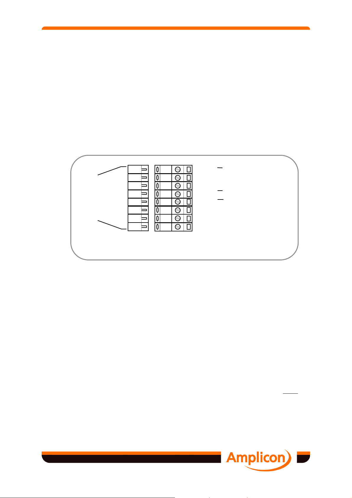
2.2.2 RS-422/485 Connections on 8 way Pluggable Terminal Strip 8
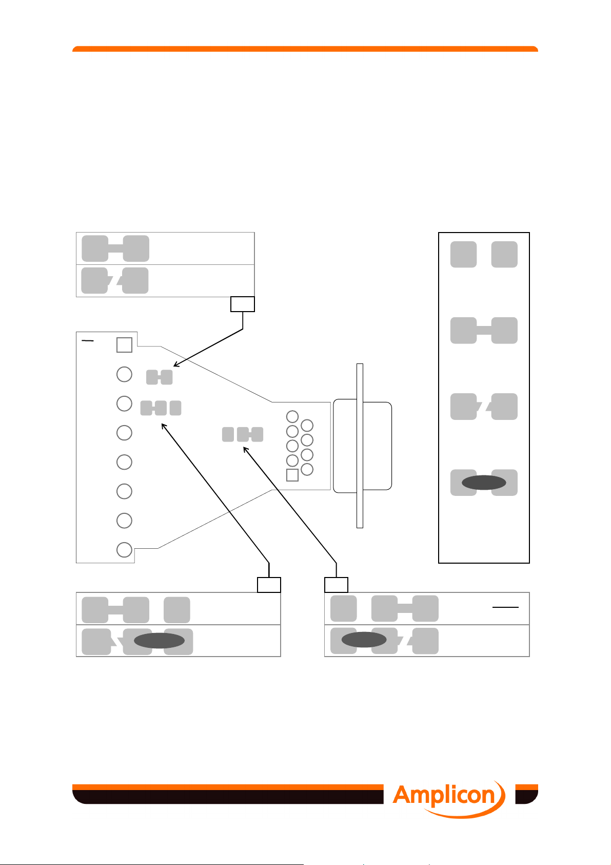
2.3 Configuration of Model 485HF9 Adaptor Options 8
2.4 Power Requirements 10
2.4.1 Connecting the Amplicon Mains Adaptor 11
2.5 Full Duplex / Half Duplex Operation 11
2.5.1 Selection of Full / Half Duplex 12
2.5.2 Selection of Transmit Enable Control Signal 12
2.5.3 Selection of Local Echo On/Off in Half Duplex Operation 13
2.6 Transmission Line Termination 13
2.6.1 Network Biasing Resistors 14
2.7 Software Installation 15
2.8 Installation Testing 15
3 APPLICATION INFORMATION 16
3.1 Applicable Standards 16
3.2 RS-232 Application Notes 16
3.2.1 Electrical Levels 17
3.2.2 9/25 Way Adaptors 17
3.3 RS-422 / 485 Application Notes 17
3.3.1 RS-422 / 485 Parameters 18
3.3.2 Cabling of RS-422 / 485 Bus 18
3.3.3 Multi-drop Applications 19
3.3.4 Bus Termination 20
4 TESTING AND TROUBLESHOOTING 21
4.1 Basic Testing and Fault Isolation 21
4.1.1 Testing with the Application Software 21
4.1.2 Loop-back Testing Using a Simple BASIC Program 21
5 TECHNICAL INFORMATION 23
5.1 Technical Specification 23
5.1.1 Electrical Specification 23
5.1.2 Physical/Environmental Specification 23
5.2 Optional Accessories 24
5.2.1 U.K. Mains Adaptor Power Supply 24
5.2.2 Universal Mains Adaptor Power Supply 24
FIG Nº TITLE PAGE
2.1 RS-232 Connections 7
2.2 RS-422/485 Connections 8
2.3 Configuration Options 9
2.4 Power Supply Connections for Single 485HF9 Adaptor 10
2.5 Power Connections for Multiple Model 485 Adaptors 11
2.6 Connections for Full and Half Duplex Operations 12
2.7 External Transmitter Enable Connections 13
2.8 Network Biasing Resistors 14
3.1 DTE Adaptor - 9 Way to 25 Way 17
3.2 RS-232/422/485 Parameters 18
3.3 RS-422 Connected in Broadcast Mode 19
3.4 RS-485 Connected in Multi-drop, Half Duplex Mode 20
4.1 Terminal Links for Loop-back Test 21
A.1 Model 485HF9 Circuit Schematic 24
MODEL 485HF9 MANUAL CONTENTS