Amplifyyourworld
3 / 13
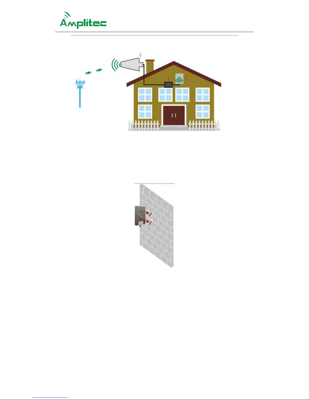
Overview
C10G-CP wide band mini Booster is designed with harmonious humanity conception, as a
perfect combination of environmental protection and signal coverage. The C10G-CP
products carried with many features like, low consumption, light weight, high gain, low
output power and easy installation, etc, It provides a rapid and perfect solution to solve
and optimize the weak signal of houses, offices, hotels, elevators, underground parking
lots and other small weak signal area.
On the condition that to assure the normal communication, C10G-CP products using the
smallest Rx and Tx power to achieve the link balance among BTS and mobile phone and
Boosters, guaranteed that the least Rx and Tx power from the products, the least harm to
environmental pollution and human body's radiation.
C10G series products has ALC and ATT function, which offer the product reliability and the
coverage stable signal technically. In addition, the C10G series products add ALC warning
directive function to let users knowing signal quality by the indicator's colour.
Function and Features
zThe system has the automatic gain control function. By comparing the voltage value
of the UL detection tube and the line detection tube with the set value, if the sampling
value is larger than the set value, then increase the attenuation value of the
corresponding channel attenuator until the corresponding detection tube voltage is
less than the set value. If the sampling value is less than the set value, then decrease
the attenuation value of the corresponding channel attenuator until the corresponding
detection tube voltage is larger than the set value or the attenuation value is 0.
The system has the output over power cut off function. When the attenuation value of
the UL or DL attenuator caused by the AGC control is more than or equal to 31dB, the
system will switch off the corresponding channel. Otherwise, when the attenuation
value is less than 31dB, turn on the corresponding channel switch.
The system has self-excited detection function. When its UL or DL occurs
self-excitation, the system shuts down the switch and keep 400 seconds, the number
of self-excited statistics plus 1. After 400 seconds, turn on the switch of UL and DL, if
continue to detect the self-excited then turn off the switch and keep 400s, the number
of self-excited statistics plus 1. If there is no self-excited, the self-excited statistics are
cleared and the system return to normal. If the self-excited is detected up to 3 times is
succession, the switch will be permanently turned off until the power off and restarted.
Any detection results in no self-excited before the permanent shut-off, the number of
self - excitation statistics will be cleared, and the system will return to normal.
zBooster is a linear amplification of the wireless signal. When the Booster is not
installed right and lead to self-excited situation, the Booster by detecting the linear
relationship between input and output to determine self-excited, if self-excitation it will
turn off their own to prevent Network with itself until troubleshooting.