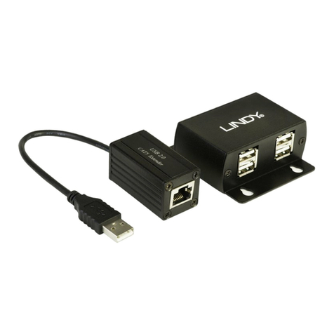
imoware USB121-100 User manual

The informatio nco ntained in this document is non-contractual and is s ubject to change without notice
Imoware USB121-100
USB 2.0 Extender (100M)
VER 1.1

The informatio nco ntained in this document is non-contractual and is s ubject to change without notice
Thank you for purchasing this product
For optimum performance and safety, please read these instructions carefully
beforeconnecting, operating or adjusting this product. Please keep this manual
for future reference.
Surge protection device recommended
This product contains sensitive electrical components that may be damaged
by electrical spikes, surges, electric shock, lighting strikes, etc. Use of surge
protection systems is highly recommended in order to protect and extend the
life of your equipment.
Table of Contents
1. Introduction...........................................................................................
1
2. Features. ................................................................................................
1
3. Package Contents................................................................................
1
4. Specifications........................................................................................
2
5. Operation Controls and Functions. .....................................................
3
5.1 Transmitter Panel.............................................................................
3
5.2 Receiver Panel................................................................................
4
6. Application Example............................................................................
5

1 / 5
The informatio nco ntai ne d int his document is non-contractual and is s ubject to change without n otice
1. Introduction
The USB 2.0 Extender can extend USB signal up to 100m / 328ft via a single
Cat5e/6 cable. In the transmitter, the USB-B port is connected to a PC. In the
receiver, you can connect a device with USB port (such as U disk or printer or
Touch Monitor, etc.) through the two USB ports. Both Transmitter and
Receiver support PoC (Power over Cable) function. The product can be widely
used for long distancesignal transmission between a PC and USB device.
Simple plug and play, no drive and installation setting required.
2. Features
☆Support USB 2.0 protocol, transmission rate is up to 200Mbps
☆Transmission distance is up to 100m / 328ft via a single CAT5e/6 cable
☆Support one USB-B port input in the transmitter
☆Support two USB 2.0 ports output in the receiver
☆Support PoC function, it means that either transmitter or receiver is powered
through 12V/1A power adapter, the other doesn’t need power supply
☆Simple plug and play, no drive and installation setting required
☆Compact design for easy and flexible installation
3. Package Contents
①1× USB 2.0 Extender (Transmitter)
②1× USB 2.0 Extender (Receiver)
③1× USB cable (USB-B male head to USB-Amale head, 1 meter )
④1× 12V/1ALocking Power Adapter
⑤1× User Manual

2 / 5
The informatio nco ntai ne d int his document is non-contractual and is s ubject to change without n otice
4. Specifications
Technical
USB Protocol
USB 2.0
Transmission Rate
Up to 200Mbps
Transmission Distance
100M (328ft)
ESD Protection
Human-body Model:
±8kV (Air-gap discharge) , ±4kV (Contact discharge)
Connection
Transmitter
Input port: 1×USB [USB-B, female]
Output port: 1×CAT [RJ45, female]
Receiver
Input port: 1×CAT [RJ45, female]
Output port: 2×USB [USB-A, female]
Mechanical
Housing
Metal Enclosure
Color
Black
Dimensions
Transmitter / Receiver: 82mm (W)×49mm (D)×20mm (H)
Weight
Transmitter / Receiver: 100g
Power Supply
Input: AC100~240V 50/60Hz
Output: DC 12V/1A (US/EU standards, CE/FCC/UL certified)
Power Consumption
Transmitter: 1.3W, Receiver: 2.3W
OperatingTemperature
0°C ~ 40°C / 32°F ~ 104°F
Storage Temperature
-20°C ~ 60°C / -4°F ~ 140°F
Relative Humidity
20~90% RH (non-condensing)

3 / 5
The informatio nco ntai ne d int his document is non-contractual and is s ubject to change without n otice
5. Operation Controls and Functions
5.1 Transmitter Panel
Number
Name
Function Description
1
USB(TO PC)
USB port, connect to the USB port of a PC through a
USB-B male head to USB-A male head wire.
2
POWER LED
Power LED indicator. The green LED will be on when the
transmitter is powered on.
3
DC 12V
Plug DC 12V/1A power supply into the unit and connect
the adapter to an AC outlet.
4
CAT port
The CAT port is connected to receiver’s CAT port via a
CAT5e/6 cable.

4 / 5
The informatio nco ntai ne d int his document is non-contractual and is s ubject to change without n otice
5.2 Receiver Panel
Number
Name
Function Description
1
USB 2.0 port
Connect to a device with USB port such as printer or U
disk, etc..
2
POWER LED
PowerLED indicator. The green LED willbe on whenthe
transmitter is powered on.
3
DC 12V
Plug 12V/1A DC power supply into the unit and connect
the adapter to an AC outlet.
4
CAT port
The CAT port is connected to transmitter’s CATport by
CAT5e/6 cable.

5 / 5
The informatio nco ntai ne d int his document is non-contractual and is s ubject to change without n otice
6. Application Example
Table of contents
