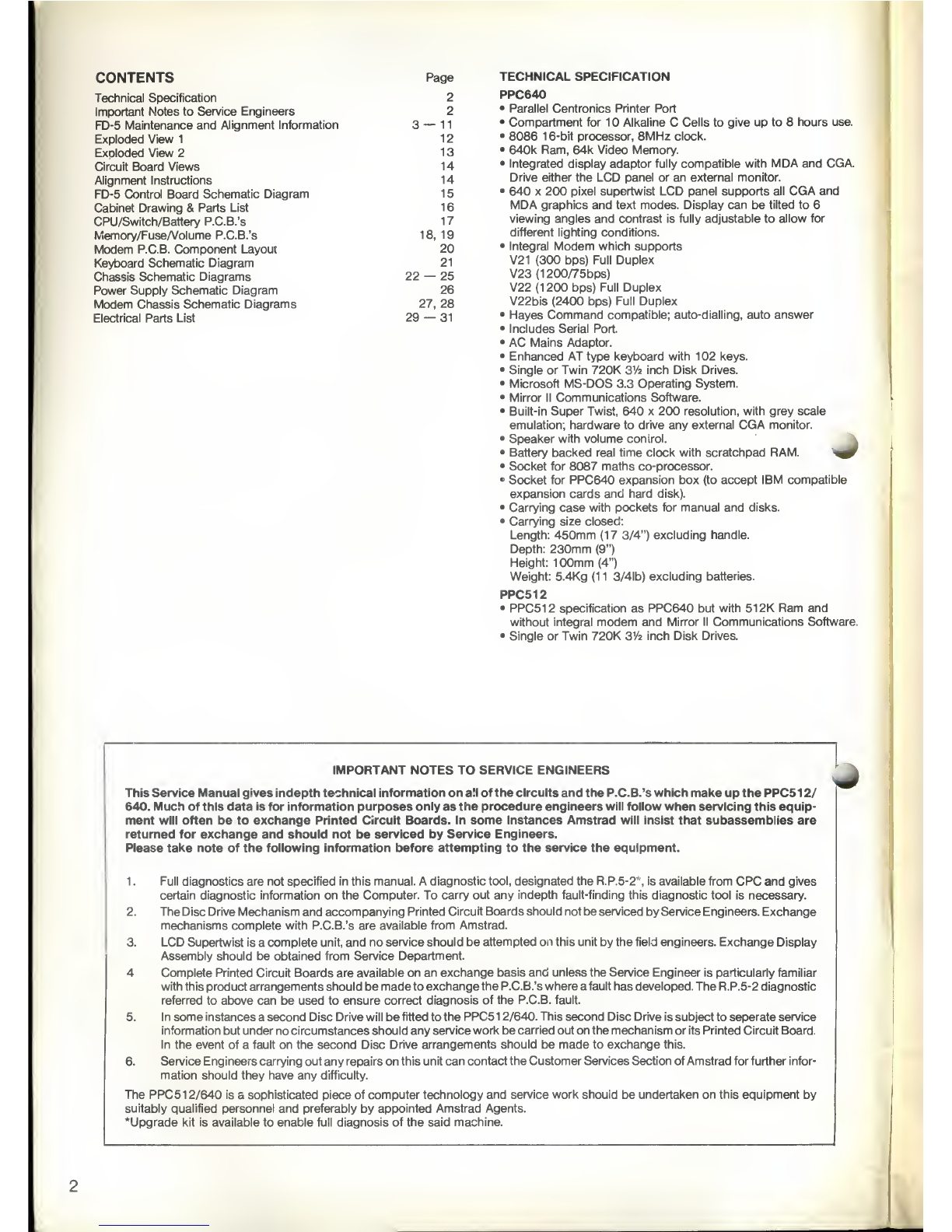
AMSTRAD PPC 640D User manual

PPC512S/512D
PPC 640S /640D
PERSONAL
PORTABLE COMPUTER
SERVICE MANUAL

CONTENTS
Technical Specification
Important Notes to Service Engineers
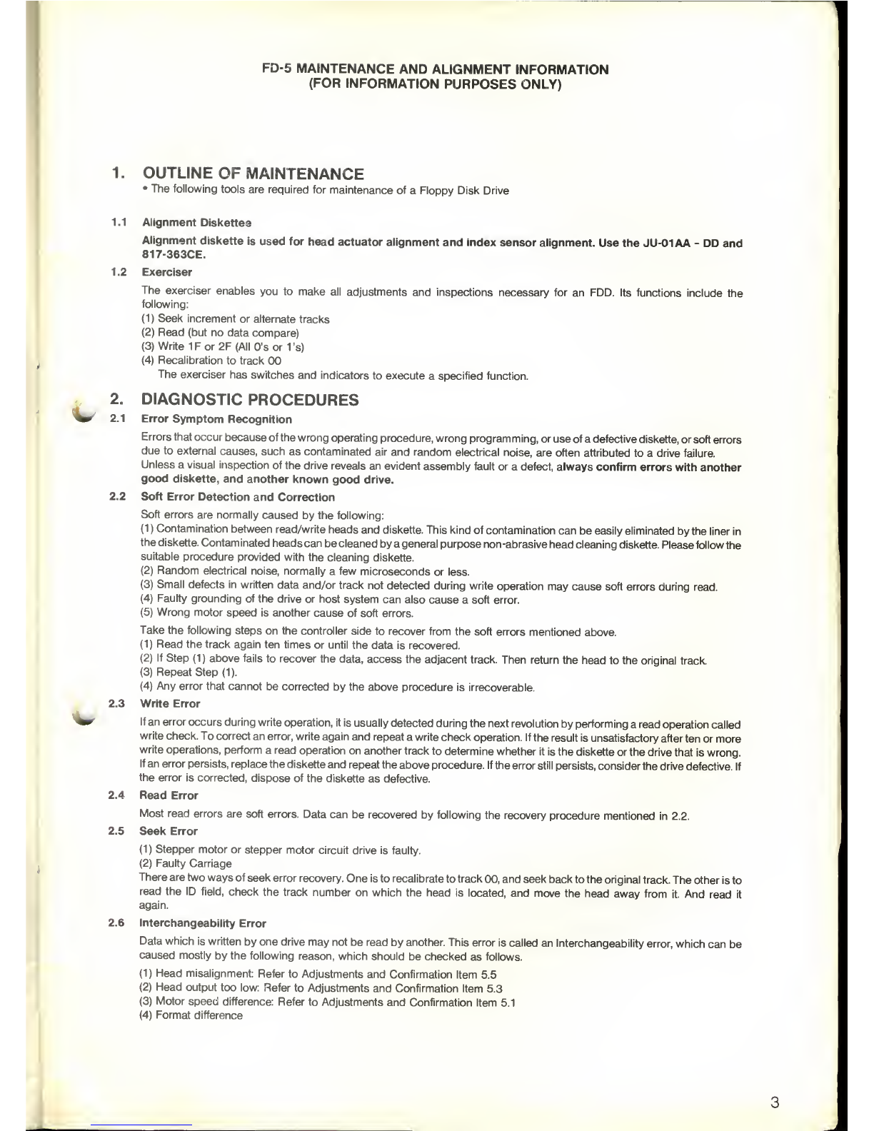
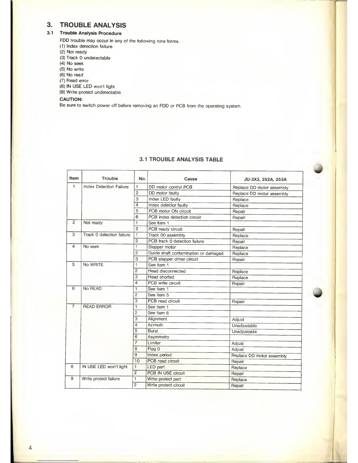
FD-5 Maintenance and Alignment Information
Exploded View 1
Exploded View 2
Circuit Board Views
Alignment Instructions
FD-5 Control Board Schematic Diagram
Cabinet Drawing &Parts List
CPU/Switch/Battery P.C.B.'s
Memory/Fuse/Volume P.C.B.'s
Modem P.C.B. Component Layout
Keyboard Schematic Diagram
Chassis Schematic Diagrams
Power Supply Schematic Diagram
Modem Chassis Schematic Diagrams
Electrical Parts List
Page TECHNICAL SPECIFICATION
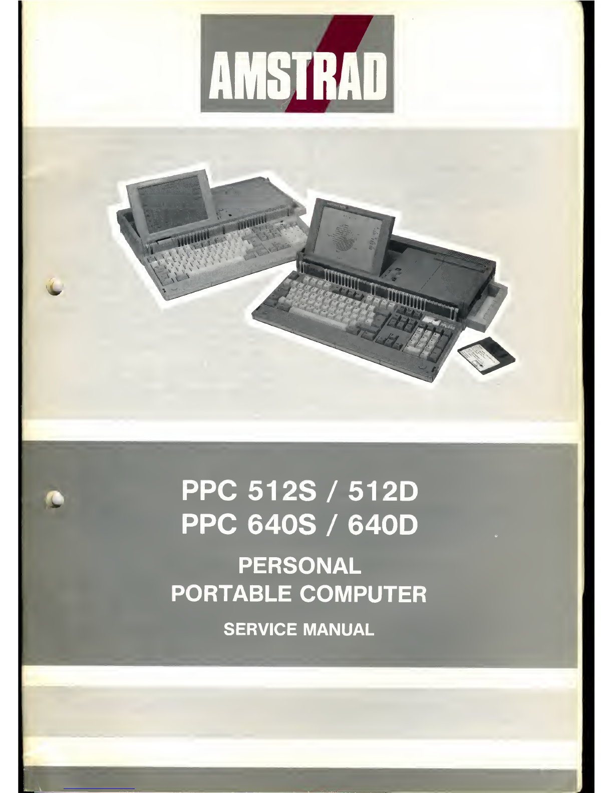
2PPC640
2•Parallel Centronics Printer Port
3—11 •Compartment for 1Alkaline CCells to give up to 8hours use.
1
2
•8086 16-bit processor, 8MHz clock.
13 •640k Ram, 64k Video Memory.
14 •Integrated display adaptor fully compatible with MDA and CGA.
14 Drive either the LCD panel or an external monitor.
1
5
•640 x200 pixel supertwist LCD panel supports all CGA and
1
6
MDA graphics and text modes. Display can be tilted to 6
1
7
viewing angles and contrast is fully adjustable to allow for
18, 19different lighting conditions.
20 •Integral Modem which supports
21 V21 (300 bps) Full Duplex
22 —25 V23 (1 200/75bps)
26 V22 (1200 bps) Full Duplex
27, 28 V22bis (2400 bps) Full Duplex
29 —31 •Hayes Command compatible; auto-dialling, auto answer
•Includes Serial Port.
•AC Mains Adaptor.
•Enhanced AT type keyboard with 102 keys.
•Single or Twin 720K 31/2 inch Disk Drives.
•Microsoft MS-DOS 3.3 Operating System.
•Mirror II Communications Software.
•Built-in Super Twist, 640 x200 resolution, with grey scale
emulation; hardware to drive any external CGA monitor.
•Speaker with volume control.
•Battery backed real time clock with scratchpad RAM. -^0
•Socket for 8087 maths co-processor.
•Socket for PPC640 expansion box (to accept IBM compatible
expansion cards and hard disk).
•Carrying case with pockets for manual and disks.
•Carrying size closed:
Length: 450mm (1 73/4") excluding handle.
Depth: 230mm (9")
Height: 100mm (4")
Weight: 5.4Kg (1 13/4lb) excluding batteries.
PPC512
•PPC512 specification as PPC640 but with 51 2K Ram and
without integral modem and Mirror II Communications Software,
•Single or Twin 720K 31/2 inch Disk Drives.
IMPORTANT NOTES TO SERVICE ENGINEERS
This Service Manual gives indepth technical information on all of the circuits and the P.C.B.'s which make up the PPC51 2/
640. Much of this data is for information purposes only as the procedure engineers will follow when servicing this equip-
ment will often be to exchange Printed Circuit Boards. In some instances Amstrad will insist that subassemblies are
returned for exchange and should not be serviced by Service Engineers.
Please take note of the following information before attempting to the service the equipment.
1
.
Full diagnostics are not specified in this manual. Adiagnostic tool, designated the R.P.5-2*, is available from CPC and gives
certain diagnostic information on the Computer. To carry out any indepth fault-finding this diagnostic tool is necessary.
2. The Disc Drive Mechanism and accompanying Printed Circuit Boards should not be serviced by Service Engineers. Exchange
mechanisms complete with P.C.B.'s are available from Amstrad.
3. LCD Supertwist is acomplete unit, and no service should be attempted on this unit by the field engineers. Exchange Display
Assembly should be obtained from Service Department.
4Complete Printed Circuit Boards are available on an exchange basis and unless the Service Engineer is particularly familiar
with this product arrangements should be made to exchange the P.C.B.'s where afault has developed. The R.P.5-2 diagnostic
referred to above can be used to ensure correct diagnosis of the P.C.B. fault.
5. In some instances asecond Disc Drive will be fitted to the PPC-51 2/640. This second Disc Drive is subject to seperate service
information but under no circumstances should any service work be carried out on the mechanism or its Printed Circuit Board.
In the event of afault on the second Disc Drive arrangements should be made to exchange this.
6. Service Engineers carrying out any repairs on this unit can contact the Customer Services Section of Amstrad for further infor-
mation should they have any difficulty.
The PPC51 2/640 is asophisticated piece of computer technology and service work should be undertaken on this equipment by
suitably qualified personnel and preferably by appointed Amstrad Agents.
'Upgrade kit is available to enable full diagnosis of the said machine.

FD-5 MAINTENANCE AND ALIGNMENT INFORMATION
(FOR INFORMATION PURPOSES ONLY)
v
1. OUTLINE OF MAINTENANCE
•The following tools are required for maintenance of aFloppy Disk Drive
1.1 Alignment Diskettes
Alignment diskette is used for head actuator alignment and index sensor alignment. Use the JU-01AA -DD and
817-363CE.
1.2 Exerciser
The exerciser enables you to make all adjustments and inspections necessary for an FDD. Its functions include the
following:
(1) Seek increment or alternate tracks
(2) Read (but no data compare)
(3) Write 1For 2F (All O's or 1's)
(4) Recalibration to track 00
The exerciser has switches and indicators to execute aspecified function.
2. DIAGNOSTIC PROCEDURES
2.1 Error Symptom Recognition
Errors that occur because of the wrong operating procedure, wrong programming, or use of adefective diskette, or soft errors
due to external causes, such as contaminated air and random electrical noise, are often attributed to adrive failure.
Unless avisual inspection of the drive reveals an evident assembly fault or adefect, always confirm errors with another
good diskette, and another known good drive.
2.2 Soft Error Detection and Correction
Soft errors are normally caused by the following:
(1) Contamination between read/write heads and diskette. This kind of contamination can be easily eliminated by the liner in
the diskette. Contaminated heads can be cleaned by ageneral purpose non-abrasive head cleaning diskette. Please follow the
suitable procedure provided with the cleaning diskette.
(2) Random electrical noise, normally afew microseconds or less.
(3) Small defects in written data and/or track not detected during write operation may cause soft errors during read.
(4) Faulty grounding of the drive or host system can also cause asoft error.
(5) Wrong motor speed is another cause of soft errors.
Take the following steps on the controller side to recover from the soft errors mentioned above.
(1) Read the track again ten times or until the data is recovered.
(2) If Step (1) above fails to recover the data, access the adjacent track. Then return the head to the original track.
(3) Repeat Step (1).
(4) Any error that cannot be corrected by the above procedure is irrecoverable.
2.3 Write Error
If an error occurs during write operation, it is usually detected during the next revolution by performing aread operation called
write check. To correct an error, write again and repeat awrite check operation. If the result is unsatisfactory after ten or more
write operations, perform aread operation on another track to determine whether it is the diskette or the drive that is wrong.
If an error persists, replace the diskette and repeat the above procedure. If the error still persists, consider the drive defective. If
the error is corrected, dispose of the diskette as defective.
2.4 Read Error
Most read errors are soft errors. Data can be recovered by following the recovery procedure mentioned in 2.2.
2.5 Seek Error
(1) Stepper motor or stepper motor circuit drive is faulty.
(2) Faulty Carriage
There are two ways of seek error recovery. One is to recalibrate to track 00, and seek back to the original track. The other is to
read the ID field, check the track number on which the head is located, and move the head away from it. And read it
again.
2.6 Interchangeability Error
Data which is written by one drive may not be read by another. This error is called an Interchangeability error, which can be
caused mostly by the following reason, which should be checked as follows.
(1) Head misalignment: Refer to Adjustments and Confirmation Item 5.5
(2) Head output too low: Refer to Adjustments and Confirmation Item 5.3
(3) Motor speed difference: Refer to Adjustments and Confirmation Item 5.1
(4) Format difference

3. TROUBLE ANALYSIS
3.1 Trouble Analysis Procedure
FDD trouble may occur in any of the following nine forms.
(1) Index detection failure
(2) Not ready
(3) Track undetectable
(4) No seek
(5) No write
(6) No read
(7) Read error
(8) IN USE LED won't light
(9) Write protect undetectable
CAUTION:
Be sure to switch power off before removing an FDD or PCB from the operating system.
3.1 TROUBLE ANALYSIS TABLE
Item Trouble No. Cause JU-3X2, 252A, 253A
1Index Detection Failure 1DD motor control PCB Replace DD motor assembly
2DD motor faulty Replace DD motor assembly
3Index LED faulty Replace
4Index detector faulty Replace
5PCB motor ON circuit Repair
6PCB index detection circuit Repair
2Not ready 1See Item 1
2PCB ready circuit Repair
3Track detection failure 1Track 00 assembly Replace
2PCB track detection failure Repair
4No seek 1Stepper motor Replace
2Guide shaft contamination or damaged Replace
3PCB stepper driver circuit Repair
5No WRITE 1See Item 1
2Head disconnected Replace
3Head shorted Replace
4PCB write circuit Repair
6No READ 1See Item 1
2See Item 5
3PCB read circuit Repair
7READ ERROR 1See Item 1
2See Item 6
3Alignment Adjust
4Azimuth Unadjustable
5Burst Unadjustable
6Asymmetry
7Limiter Adjust
8FlagO Adjust
9Index period Replace DD motor assembly
10 PCB read circuit Repair
8IN USE LED won't light 1LED part Replace
2PCB IN USE circuit Repair
9Write protect failure 1Write protect part Replace
2Write protect circuit Repair

w
4. PREVENTIVE MAINTENANCE
No preventive maintenance is necessary for any type of FDDs under normal conditions of use.
However if it is determined that adjustments are necessary, the following must be done.
•Adjustments (Refer to table 4.1)
(1) Specify an applicable model from Table 4.1, and make aread/write head radial adjustment at aspecified track.
(Sides 0,1)
(2) Make an index timing adjustment at aspecified track. (Sides 0,1).
(3) Make an azimuth measurement at aspecified track (Sides 0,1)
CAUTION
Do not write when using alignment diskette. Check that write protect sensor is properly operating with adata diskette.
Note: Section 9describes the adjustment procedures in detail.
5. ADJUSTMENTS AND VERIFICATIONS
5.1 Motor Speed Verification (Index Period)
(1) Insert adiskette, run the motor, and clamp. Refer to the index period column of Table 4.1 for the applicable model.
(2) Step to the specified track.
(3) Connect afrequency counter to the INDEX signal.
IX (INDEX)
(4) Check that the frequency counter readings meet the specifications in the table.
5.2 Write Protect Verification
(1) Check that the exerciser's write protect lamp goes on and off as amedia is inserted and removed as specified in the
table below.
Media with write protect hole open: ON
Media with write protect hole closed: OFF
5.3 Head Output Verification
Use anew diskette if possible to identify head failure for this check.
(1) Insert agood diskette.
(2) Run the motor.
(3) Step to the track specified in the output level column of Table 4.1.
(4) Connect the oscilloscope probe as specified below.
CH1 :T1
CH2 :T2
EXT :IX (Index)
Invert channel 2 and select the Add mode.
Set vertical deflection to 10mV/division and horizontal deflection to 20ms/division.
(5) Write 2F (all ones) on the entire circumference.
(6) Check that the average output level meets the specifications of Table 4. 1.If it does not meet the spec-ifications, refer to item
7of the Trouble Analysis Table.
5.4 Output Modulation Verification
Modulation: Mis calculated by the following formula.
M(%) =Vmax -Vmin x100 using the value obtained in 5.3, and check that the calculated value is 20% or less.
M(%) =Vmax +Vmin
i'
',
]
11
'
1
Maximum Voltage Value :Vmax
Average Voltage
Minimum Voltage Value :Vmin
Fig. 5.1 Modulation

3.2 Trouble Shooting Flow Chart
(
Run the operating system and
check. Record all diagnostic
information on tracks and sectors
as far as the program permits.
Install Exerciser on FDD
Power SW
DCSWON MOTSWON
Drive Select SW
ON
YES
Set Address SW to Track
YES
Write SW ON
YES
Write SW OFF
YES
FDD online test
rCheck Item 4,
Table 3.1
NO Check Item 5,
Table 3.1
Check Item 6,
Table 3.1

5.5 Radial Alignment Adjustment
Introduction
This adjustment is normally not necessary.
If the mounting screws for the steeper motor loosen, or if parts become defective, or if acompatibility error occurs, check and
readjust according to the following procedure.
Steps (4) and (9) below should be performed regardless of the type, CE or DAD alignment diskette used. Use an alignment dis-
kette suitable to the type of FDD to be adjusted according to table.
(1) Insert an alignment diskette.
CAUTION:
Be sure to leave the alignment diskette under room conditions for 20 minutes before adjustment.
(2) Step to the track specified in the Radial alignment column of Table 4.1.
(3) Leave the oscilloscope in the same condition as mentioned in section 5.3.
•Cats Eye System
(4) Check the output waveforms for sides and 1. They should appear as in Fig. 5.2.
(5) The two waveforms should appear in the amplitude ratio in the R/A +/- 42% or more.
(6) If the specified ratio is not satisfied, loosen the two mounting screws for the stepper motor.
(7) Move the stepper motor along the base by hand until the two waveforms assume approximately the same amplitude, and
retighten the mounting screws. (See Fig. 5.2).
(8) Step the head outward (track 0) and inward (track 40 or 79), and confirm that the adjustment has been completed.
(9) After the intitial adjustment, be sure to confirm track 00 sensor adjustment 5.8 and carriage limiter 5.9.
--
lI/1l
-1/s. -
U-44-
1,
U- III 1i-W-C li-U- 1II
1
E
-M Mi-4-U
->'-
,1 ''
- -
A>B
8>A
X100
X 100
Fig. 5.2 Radial Alignment Waveforms (CATS EYE)
Note: Alignments on sides and 1are adjusted at the factory. If they are misaligned, adjust
them to meet the specifications of Table .
DAD (Dynamic Alignment Diskette)
(4) Watch the output waveforms for sides and 1. They should appear as shown in Fig. 5.3.
(5) Measure the timing levels A1 to A4 and B1 to B4 in Fig. 5.3., and calculate the lobe ratio from the following
formulas.
LA >SB ZB x100%
LA LA (SB :LA x100%
SB
(6) The lobe ratio calculated by the above formulas should meet the specifications on item 3of Table.
(7) If the above requirement is not met, loosen the two mounting screws for the stepper motor, adjust.
(8) Seek from track to track 40 and from track 79 to track 40, and confirm that the adjustment has been completed.
(9) After the radial adjustment, be sure to confirm track 00 sensor adjustment 5.8 and head carriage limiter 5.9.
Note: An alignment instrument for 3.5 inch FDDs permits accurate and easy adjustment
because the lobe ratio is displayed on the instrument.

~]fAzimuth
waveforms
Index
burst
waveform
20 ms |
"IT
Radial alignment waveforms
70 ms 120 ms 170 ms
Fig. 5.3 Alignment Waveform (DAD)
5.6 Azimuth Verification
(1) insert an alignment diskette. Seek to the track specified in the azimuth column of Table 4.1.
(2) Set the oscilloscope in the same conditions as in 5.3., and set horizontal deflection to 2ms/div (DAD) or 0.5 ms/div
(CE).
(3) Measure as shown below.
(4) Confirm that the measured value meets the specifications in the azimuth column of Table 4.1.
BC
A
m
Ui LAI
D
IT
Azimuth 0' waveforms
Case of B>C (+)
B—C
Azimuth =-x(A)
B—u
(A) :CE—30'
DAD— 15'
Case of OB(-)
C—B
Azimuth *- x(A)
a
Fig. 5.4 Azimuth Waveforms
5.7 Index Burst Verification and Adjustment
(1) Insert an alignment diskette. Seek to the track specified in the l/B column of Table 4.1.
(2) Set the oscilloscope time base as follows: 1ms/division.
(3) Check that the time from oscilloscope start to the first data pulse meets the l/B specifications of Table 4.1. (DAD
SYSTEM).
8

Index Burst
Fig. 5.5 Index Timing
5.8 Track 00 Sensor Adjustment
(1) Set the oscilloscope as follows:
Set horizontal deflection to 1ms/division.
CH1 :ZP
EXT :SP
(2) Step between specified tracks at in the FLAG item of Table 4.1 .(Turn the seek delay switch on the exerciser to adjust
12ms seek).
(3) Loosen the track sensor screw and adjust until the waveform on the oscilloscope appears as shown in Fig. 5.6.
ADJUST A: BTO 1:1
Fig. 5.6 Track Waveform
5.9 Limiter Verification
(1) Seek to track 0.
(2) Write 2F data on track 0, and measure read level.
(3) Seek to track -1, and check that the head just touches the limiter.
(4) Check that, when the RECAL switch on the exerciser is pushed ON, the head returns to track and that the 2F output level
is the same as that measured in Step (2).

Fig. 5.7 Asymmetry Waveform
(Asymmetry Wave form might be reversed up-and-down from model to model )
5.10 Asymmetry Verification
(1) Insert adata diskette.
(2) Step to the track specified in the symmetry item of Table 4.1.
(3) Set the oscilloscope as follows:
CH1 :RD
CH2 :T1
Set time base to 1us/division and vertical deflection to 0.2 v/division.
(4) Write 1F.
(5) Aread wave form is displayed on the oscilloscope as shown in Fig. 5.7.
(6) Confirm if it satisfies the value as shown in Table 4.1.
(Asymmetry wave form might be reversed up-and-down from model to model).
ALIGNMENT CASSETTE
3.5 inch Alignment Diskette
TP1 P/N Index Burst Azimuth Radial Alignment MODEL
135 DAD
135 CE
JU-01AA
817-363CE
40TRK 40TRK 40TRK JU-252A
JU-253A
V
MEASUREMENT ITEMS TABLE 4.1
10
Item Parameter JU-252A, 253A
TRK Value
1Index Period 40 200 ±2ms
2Output Level 79 80mV or more
3Radial Alignment
Reference (DAD)
Reference (CE by 817-363CE)
40 ±35(im
(29% or more)
(42% or more)
4Azimuth 40 ±24'
5Index burst 40 3± 1.7ms
6FlagO From track to track 1
and back TROO (TROO: Low, Tr1 :Height)
7Limiter -1 Recalibrate and return to
8Asymmetry 79 <700NS

TEST POINTS
«:
<
r
uu
Q
D
11

EXPLODED VIEW —1
12

EXPLODED VIEW —2
13

Component Side
CIRCUIT BOARDS
L3
)i33JC3 23
22
mI
6580K '
J
T"1T*U12
XI
49
10
J6
26<
IC1
10
J5
33
MN50007LF
32
IC2
e73
,
'n
VR1—*"
IIRI DS9
Jl JL II
lo
ittefl ,J4 J
3
YM I.' ,,
4
Lfnrl<
lx iDi
SP wn
Wti to
WP
5S RD
RY
ZH Mn
US
GNO 5V
«
—
16
34
33 DO" 03 TP-NI-7H-T
FPK0158AB3
Solder Side
iHi. IN dl ea785io»dd
ICCIf |/^ it u u
-' u ja. aa
b^rf H+i |+H
-1-5 1Si« IIII
-
1
J
'n/" m
jL-hW" -"I
*» CO U< *"? "* 1™I
u«
sp-
ON9
SO AS
il ou
St id
j« Ob
0*
IB IS
\n
BHHHHH
-jii ;—i,n
Si 10
ut
ALIGNMENT INSTRUCTIONS FOR PPC512/640
Equipment required: Digital Multimeter; D.B.O.Scope; Diagnsostic Disc/Tool.
Step FUNCTION SIGNAL IN SIGNAL OUT METHOD REMARKS
1. Set RTC X-103 Connect Odometer to
Pin 21 IC134.
Set Odometer to 0.2sec/Day. Adjust it to
read 0.00 with TC1 01. Do this adjustment only if the real
timeclock chil is changed.
2. Set +SV. Power On. June, of L501 &C514. Adjust VRS01 to get 5V ±5%. Use Power Adaptor to power PPC.
14

FD-5 SCHEMATIC DIAGRAM
TRACK ZERO
-DRIVE SELECT
3
|(§)
2I®
1(53
-SIDE SELEC.
-DIRECTION |®^S:
-WRITE GATE |
•WRITE DATA
GND ld^n©-<S
GND |c3>^ oso^
l_JI
©WD
UN2215 Jf

MM OF CONTROL BOARD
I©1
!-DISK CHANGE
;<§)'- READY
(+0ISKIN)
a
J
L4 150iJH
15

CABINET DRAWING PPC 512/640/S/D
CABINET PARTS LIST PPC512 S/D, PPC640 S/D
16
Ref. Description Part No. Part No.
PPC51 2S/D PPC640S/D
1Cover FDD 177201 177202
2Frame FDD 177203 177204
3Cabinet Top LCD 177205 177206
4Cabinet Bottom LCD 177207 177208
5Cabinet Main Top Ass'y 177209 177210
6Lid Compartment 177211 177212
7Knob Volume 177213 177214
8 Cover Power Switch 177215 177216
9Cabinet Main Bottom Ass'y "S" 177217 177218
Cabinet Main Bottom Ass'y "D" 177217/A 177218/A
10 Expansion Connector Door 177219 177220
11 Lid Battery 177221 177222
12 Handle 177223 177224
13 Lid Key Board 177225 177226
14 Cabinet Top Key Board 177227 177228
15 Screw Cap 177229 177230
16 Stud (A) 177231 177232
17 Stud (B) 177233 177234
18 Cabinet Bottom Key Board 177235 177236
19 Knob Slide (L) 177237 177238
20 Knob Slide (R) 177239 177240
21 Holder Slide Knob 177241 177242
22 Spring Slide Knob 177243 177244
23 Super Twist LCD Screen 177245 177245
24 FD-5 Floppy Disc Drive 177247 177248
25 PCB LED 177249 177249
26 PCB Fuse 177251 177251
27 PCB Volume/Contrast 177253 177253
28 Slide Switch Power On/Off 177255 177255
29 PCB Power Supply/Memory 177257 177257
30 PCB CPU Ass'y 177259 177259
31 Blanking Cover "S" 177261 177262
32 PCB Modem 177322

a,I'
<$>
it
•i^
T
O
~»8
,
+
M
e
t
an**mn
»•
X
uD
ED
O
ru
«
ID Q>
EH
u< i4
1
$&—%®
;##
•
»
ii *\«m*
s#
•-
**ru
i 1 ^:
-
-f
w
~
2
t? *
mi &z—Tt 1
.1 *) •
if./ »..«
2:'' =s-I2
iii
*\ ,#
-:;:;:;. '
'fX
~..
«
«
a8-8-
ie13

^
<n
CO
6
a."
>-
cc
Hi
<
CD
I
17

MEMORY/FUSE/VOLUME P.C.B.
e< Z
-
18
Other AMSTRAD Laptop manuals