manuals.online logo
Brands
  1. Home
  2. •
  3. Brands
  4. •
  5. andrews
  6. •
  7. Fan
  8. •
  9. andrews ASF21 Product information sheet

andrews ASF21 Product information sheet

This manual suits for next models

1

Other andrews Fan manuals

andrews DE 25 Product information sheet

andrews

andrews DE 25 Product information sheet

andrews ASF 950 User manual

andrews

andrews ASF 950 User manual

Popular Fan manuals by other brands

Minka Group minkaAire Wave F843 instruction manual

Minka Group

Minka Group minkaAire Wave F843 instruction manual

Airflow Adroit DV50 instruction manual

Airflow

Airflow Adroit DV50 instruction manual

Vornado 270 Series owner's guide

Vornado

Vornado 270 Series owner's guide

comfort air TH-10D instruction manual

comfort air

comfort air TH-10D instruction manual

Livoo DOM386 instruction manual

Livoo

Livoo DOM386 instruction manual

Holmes BLIZZARD HAOF-90 owner's guide

Holmes

Holmes BLIZZARD HAOF-90 owner's guide

Taurus GRECO 16 ELEGANCE manual

Taurus

Taurus GRECO 16 ELEGANCE manual

Quorum PINNACLE installation instructions

Quorum

Quorum PINNACLE installation instructions

Monte Carlo Fan Company 3DIR58RBD-V1 Owner's guide and installation manual

Monte Carlo Fan Company

Monte Carlo Fan Company 3DIR58RBD-V1 Owner's guide and installation manual

Craftmade UH52 installation guide

Craftmade

Craftmade UH52 installation guide

Jocel JVA030658 instruction manual

Jocel

Jocel JVA030658 instruction manual

MIKA MFB1211/GR user manual

MIKA

MIKA MFB1211/GR user manual

Harbor Breeze RLG52NWZ5L manual

Harbor Breeze

Harbor Breeze RLG52NWZ5L manual

Allen + Roth L1405 instruction manual

Allen + Roth

Allen + Roth L1405 instruction manual

ViM KUBAIR F400 ECOWATT Technical manual

ViM

ViM KUBAIR F400 ECOWATT Technical manual

HIDRIA R10R-56LPS-ES50B-04C10 user guide

HIDRIA

HIDRIA R10R-56LPS-ES50B-04C10 user guide

BLAUBERG Ventilatoren CENTRO-M 100 L user manual

BLAUBERG Ventilatoren

BLAUBERG Ventilatoren CENTRO-M 100 L user manual

Triangle Engineering HEAT BUSTER SPL Series owner's manual

Triangle Engineering

Triangle Engineering HEAT BUSTER SPL Series owner's manual

manuals.online logo
manuals.online logoBrands
  • About & Mission
  • Contact us
  • Privacy Policy
  • Terms and Conditions

Copyright 2025 Manuals.Online. All Rights Reserved.

ASF21/50
Cooling & Ventilation Fans
Operating Instructions
& Safety Guide
Set up & operation
Set the unit up on a f rm, level surface and do not site the unit close to
any personnel wearing contact lenses, sensitive to any dust movement,
hay fever sufferers etc. This unit moves air only, but minute particles
of dust / pollen etc will also be moved, especially on highest fan
setting, so careful location / fan angle / use of speed control will require
consideration.
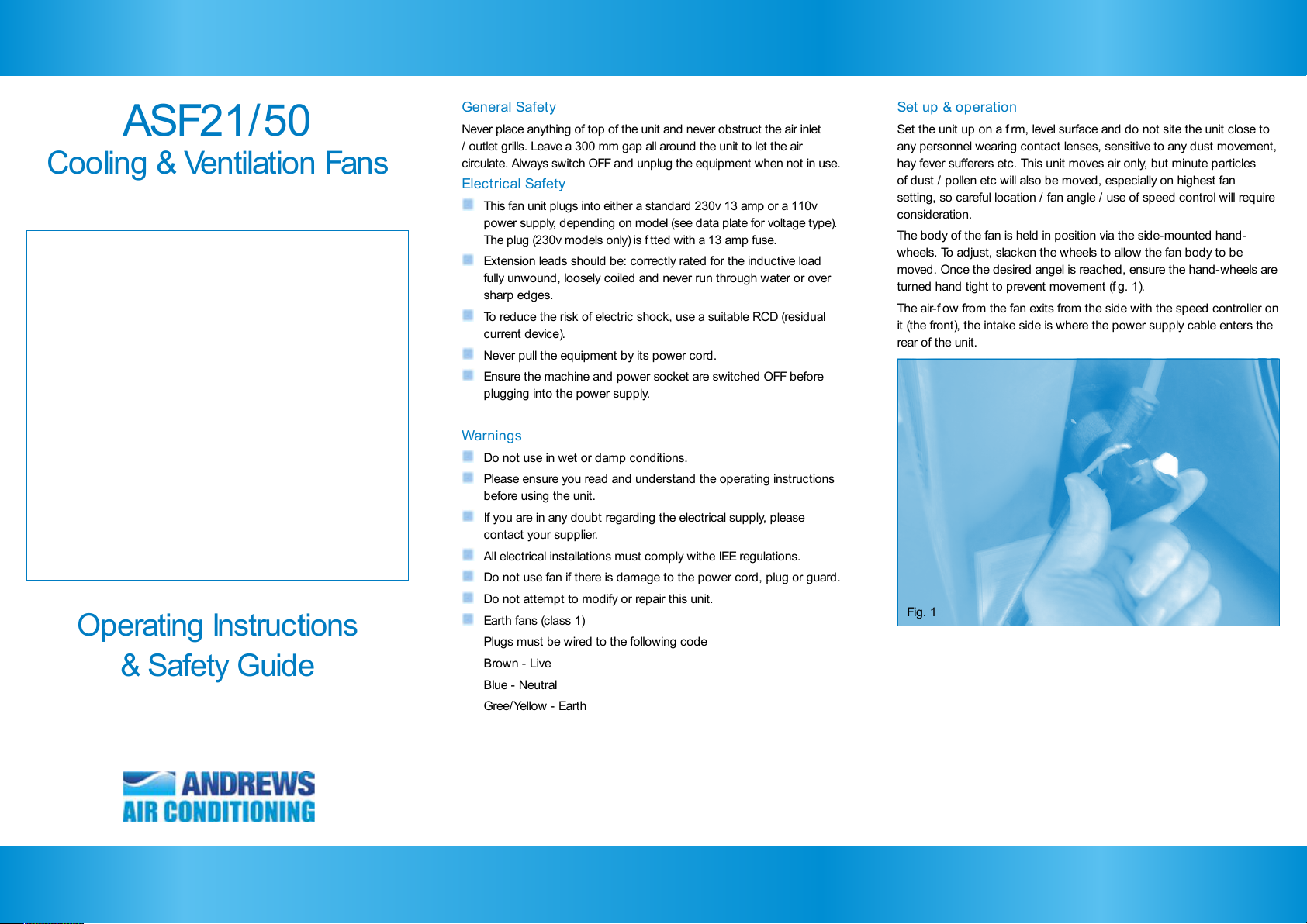
The body of the fan is held in position via the side-mounted hand-
wheels. To adjust, slacken the wheels to allow the fan body to be
moved. Once the desired angel is reached, ensure the hand-wheels are
turned hand tight to prevent movement (f g. 1).
The air-f ow from the fan exits from the side with the speed controller on
it (the front), the intake side is where the power supply cable enters the
rear of the unit.
General Safety
Never place anything of top of the unit and never obstruct the air inlet
/ outlet grills. Leave a 300 mm gap all around the unit to let the air
circulate. Always switch OFF and unplug the equipment when not in use.
Electrical Safety
This fan unit plugs into either a standard 230v 13 amp or a 110v
power supply, depending on model (see data plate for voltage type).
The plug (230v models only) is f tted with a 13 amp fuse.
Extension leads should be: correctly rated for the inductive load
fully unwound, loosely coiled and never run through water or over
sharp edges.
To reduce the risk of electric shock, use a suitable RCD (residual
current device).
Never pull the equipment by its power cord.
Ensure the machine and power socket are switched OFF before
plugging into the power supply.
Warnings
Do not use in wet or damp conditions.
Please ensure you read and understand the operating instructions
before using the unit.
If you are in any doubt regarding the electrical supply, please
contact your supplier.
All electrical installations must comply withe IEE regulations.
Do not use fan if there is damage to the power cord, plug or guard.
Do not attempt to modify or repair this unit.
Earth fans (class 1)
Plugs must be wired to the following code
Brown - Live
Blue - Neutral
Gree/Yellow - Earth
Fig. 1
0
0
1
2
3
4
5
6
7
8
9
10
Equipment care & storage
Never use an air mover except for its intended purpose.
Keep the equipment clean & especially the grill faces. Blow out the
grills with compressed air if ‘clogged’ up.
Never move the unit whilst in operation!
Switch the unit OFF and unplug from its power supply, wrap the
cable round the storage ears.
Operating Instructions - ASF21/50
Troubleshooting
Below is a trouble shooting guide, which will help should any diff culties
be experienced.
Always consult this guide before ringing your supplier. The majority of
reported problems are simply solved in this manner.
If none of the above solves the problem, please contact your supplier
for advice
Problem Likely Cause Solution
Unit fails to operate Power failure Check unit is plugged in to power supply
Check plug fuse (230v only) for failure &
correct 13 amp rating
110v Models, check power supply
Check building ring circuit is not overloaded
Poor airf ow Speed control on low
setting
Grills dirty
Air inlet grills obstructed
Turn speed control knob clockwise to
increase airf ow
Blow compressed air through grills to clean
Remove obstruction
Operation
To start
Plug the unit into the relevant power supply and switch the supply ON
(f g. 2).
Press the red ‘rocker’ switch on the front of the unit to ON, which will
then illuminate.
The fan blade should immediately start to turn & the speed can be
controlled with the knob on the control panel. Do not force the knob
past the stop point; you will damage the switchgear.
To stop
Move the on/off switch to the off position. Isolate from electrical supply
when not in use.
Fig. 2
On indicator
I
On/Off switch
Off indicator
Fan speed controller
10 being maximum