Anodyne Electronics Manufacturing AWG08-001 User manual

CONFIDENTIAL AND PROPRIETARY TO ANODYNE ELECTRONICS MANUFACTURING CORP.
INSTALLATION AND OPERATION MANUAL
Document # AWG08-IOAWG08
REV 1.01January 21, 2019
Anodyne Electronics Manufacturing Corp.
15-1925 Kirschner Road
Kelowna, BC, Canada.
V1Y 4N7
Telephone: +1-250-763-1088
Toll Free: +1-888-763-1088
Website: www.aem-corp.com
© 2019 Anodyne Electronics Manufacturing Corp. (AEM),
All Rights Reserved
ASM-AWG08
AWG08-001
Audio Warning Generator

AWG08-001 Audio Warning Generator
Installation and Operation Manual
Installation and Operation Manual Page ii
ENG-FORM: 820-0100.DOTX
CONFIDENTIAL AND PROPRIETARY TO ANODYNE ELECTRONICS MANUFACTURING CORP.
COPYRIGHT STATEMENT
© 2019 Anodyne Electronics Manufacturing Corp. (AEM), All Rights Reserved
This publication is the property of AEM and is protected by Canadian copyright laws.
No part of this document may be reproduced or transmitted in any form or by any means
including electronic, mechanical, photocopying, recording, or otherwise, without the prior
written permission of AEM.

AWG08-001 Audio Warning Generator
Installation and Operation Manual
Installation and Operation Manual Page iii
ENG-FORM: 820-0100.DOTX
CONFIDENTIAL AND PROPRIETARY TO ANODYNE ELECTRONICS MANUFACTURING CORP.
Prepared By: Checked By: Approved By:
The status of this installation and operation manual is controlled by the revision shown on the title page.
The status of each section is controlled by revision shown in the footer of each page. All revisions affecting
sections of this manual have been incorporated.
AEM MANUAL REVISIONS
Section Revision Number Revision Description Date
Cover Rev: 1.01
ECO 1078:
-
Jan 21, 2019
All Rev: 1.00 Initial release Nov 26, 2018
Adam Pembleton
Designer
Jan 21, 2019
Nikolis Andrews
Designer
Jan 22 2019
Tom Betzelt
Product Support
Manager
Jan 22, 2019
Todd Blackstock
R&D Manager
Jan 22/19

AWG08-001 Audio Warning Generator
Installation and Operation Manual
Installation and Operation Manual Page iv
ENG-FORM: 820-0100.DOTX
CONFIDENTIAL AND PROPRIETARY TO ANODYNE ELECTRONICS MANUFACTURING CORP.
Table of Contents
Section Title Page
1.0 Description
1.1 Introduction 1-1
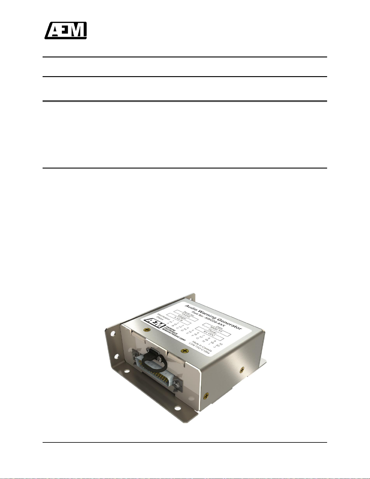
1.2 Product Description 1-1
1.2.1 Product Identifier Description 1-2
1.3 Design Features 1-2
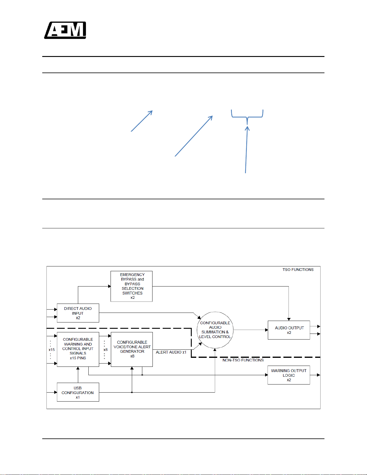
1.3.1 TSO and Non-TSO Functions 1-2
1.3.2 Warning Audio Storage [Non-TSO] 1-3
1.3.3 Warning Audio Playback [Non-TSO] 1-4
1.3.4 Warning Audio Cancelation [Non-TSO] 1-5
1.3.5 Warning Trigger Inputs [Non-TSO] 1-5
1.3.6 Warning Audio Test [Non-TSO] 1-6
1.3.7 Warning Trigger Disable [Non-TSO] 1-6
1.3.8 Slave Input [Non-TSO] 1-6
1.3.9 Master Output [Non-TSO] 1-7
1.3.10 External Warning Active Input [Non-TSO] 1-7
1.3.11 Warning Audio Pause [Non-TSO] 1-7
1.3.12 Emergency Mode 1-8
1.3.13 Maintenance Mode [Non-TSO] 1-8
1.3.14 Audio Options and Configuration [Non-TSO] 1-8
1.3.15 Warning Active Output [Non-TSO] 1-8
1.4 Specifications 1-9
1.4.1 Electrical Specifications 1-9
1.4.2 Physical Specifications 1-13
1.4.3 Environmental Specifications 1-14
1.4.4 Product Approval/Certification 1-14
1.5 Product Limitations 1-14
1.5.1 Installation Procedures and Limitations 1-14
1.5.2 USB Connector Bonding [Non-TSO] 1-14
1.5.3 Audible Pop and Click Performance 1-14
1.5.4 Power On Transients 1-14
1.5.5 User Configurable Settings [Non-TSO] 1-15
1.5.6 Embedded Programmer [Non-TSO] 1-15
1.6 Additional Requirements 1-15
1.6.1 Bonding 1-15
2.0 Installation
2.1 Introduction 2-1
2.2 Unpacking and Inspection 2-1
2.2.1 Warranty 2-1
2.3 Installation Procedures 2-1
2.3.1 Warnings 2-1
2.3.2 Cautions 2-1
2.3.3 Cabling and Wiring 2-2
2.3.4 Post-Installation Checks 2-2
2.4 Adjustments and Connections 2-3
2.4.1 Direct Audio Inputs 2-4
2.4.2 Warning Level [Non-TSO] 2-4

AWG08-001 Audio Warning Generator
Installation and Operation Manual
Installation and Operation Manual Page v
ENG-FORM: 820-0100.DOTX
CONFIDENTIAL AND PROPRIETARY TO ANODYNE ELECTRONICS MANUFACTURING CORP.
2.4.3 Audio Outputs 2-4
2.4.4 Level Adjustments 2-4
2.4.5 Emergency Audio Path Adjustments 2-5
2.4.6 Audio Path Adjustments 2-6
2.5 Accessories Required But Not Supplied 2-6
2.6 Continued Airworthiness 2-6
2.7 Installation Drawings 2-7
3.0 Operation
3.1 Introduction 3-1
3.2 General 3-1
3.3 System Interfaces 3-1
3.3.1 Inputs 3-1
3.3.2 Outputs 3-2
3.4 System Operations 3-2
3.4.1 Audio Summing 3-2
3.4.2 Audio Summing [Non-TSO] 3-2
3.4.3 Warning Audio and Setting Configuration [Non-TSO] 3-2
3.4.4 External Warning Active [Non-TSO] 3-2
3.4.5 Trigger Priority [Non-TSO] 3-2
3.4.6 Warning playback [Non-TSO] 3-3
3.4.7 Master/Slave [Non-TSO] 3-4
3.4.8 Emergency 3-4
3.4.9 Input Mute During Warning Playback [Non-TSO] 3-4
3.4.10 Warning Audio Pause [Non-TSO] 3-4
3.4.11 Warning Audio Cancel [Non-TSO] 3-4
3.4.12 Block Diagram 3-5

AWG08-001 Audio Warning Generator
Installation and Operation Manual
January 21, 2019 Rev: 1.01 Page 1-1
ENG-FORM: 800-0100.DOTX
CONFIDENTIAL AND PROPRIETARY TO ANODYNE ELECTRONICS MANUFACTURING CORP.
Section 1.0 Description
1.1 Introduction
Information in this section consists of product description, design features and specifications for the AWG08
audio warning generator. All derivative product information will be contained in the applicable manual
supplement, which may be obtained from AEM as required.
Review all notes, warnings and cautions.
1.2 Product Description
The AWG08 AudioWarning Generator is a bulkhead mount unit intended for applications where an audible
warning is desired by the operator. The AWG08 can contain up to eight warnings in the form of a tone or
voice or combination thereof. The AWG08 provides two un-switched, adjustable (direct) auxiliary audio
inputs to be summed with the warning audio. Pre-summed input level is adjustable via externally accessible
trimpots. The AWG08 hastwo isolated andindependently adjustable audio outputs, with built-in short circuit
protection.
The AWG08 can playback up to eight stored, audible warnings from individual trigger inputs. The audible
warnings are configurable using a personal computer (PC) Application. The audible warnings are stored in
an internal non-volatile memory and are user configurable to playback once (Single Shot) or to playback
continuously (Repeating).
The AWG08 can be configured as master/slave combinations to daisy chain multiple units.
The AWG08includesa warning active output which is intended to connect to an external relay or an external
annunciator(s). The warning active output is active if the AWG08 is playing an audible warning.

AWG08-001 Cabin PA Amplifier
Installation and Operation Manual
January 21, 2019 Rev: 1.01 Page 1-2
ENG-FORM: 800-0100.DOTX
CONFIDENTIAL AND PROPRIETARY TO ANODYNE ELECTRONICS MANUFACTURING CORP.
1.2.1 Product Identifier Description
AWG08-yzz
1.3 Design Features
This section contains descriptions of the AWG08-001 design features and default factory settings.
1.3.1 TSO and Non-TSO Functions
The AWG08 contains qualified TSO and qualified Non-TSO functions. The block diagram below provides
a visual representation of the Non-TSO and TSO functions in the AWG08. The Non-TSO functions will be
indicated throughout the document headings as “[Non-TSO]”.
Base Product Identifier
System Identifier
Derivative Product Identifier

AWG08-001 Audio Warning Generator
Installation and Operation Manual
January 21, 2019 Rev: 1.01 Page 1-3
ENG-FORM: 800-0100.DOTX
CONFIDENTIAL AND PROPRIETARY TO ANODYNE ELECTRONICS MANUFACTURING CORP.
1.3.2 Warning Audio Storage [Non-TSO]
The AWG08 is able to store up to eight stored digitally sampled warning tones or messages. The warnings
are configurable by use of a PC Application. The warning’s digitally sampled data is stored on internal non-
volatile memory.
The AWG08 may be factory configured to store four warnings/messages with extended message lengths.
The AWG08 utilizes memory modules with a playback endurance of >100k cycles and message retention
of >10 years.
The AWG08-001 user configurable audio is preloaded from factory with the following warnings in their
respective trigger locations as described below:
Trigger
Position
File Name
Pre-loaded
Message
Length (s)
Max
Message
Length (s)
Trigger 1
Voice Engine Fire Female.wav
~1.0
85 /170
Trigger 2
Voice Rotor High Male.wav
~1.0
85 /170
Trigger 3
Voice Rotor Low Male.wav
~1.0
85 /170
Trigger 4
VA Pull Up Female.wav
~3.2
85 /170
Trigger 5*
Alert OVERSPD.wav
~0.9
85 / -
Trigger 6*
Voice Altitude Female.wav
~0.8
85 / -
Trigger 7*
Voice Decision Height Male.wav
~1.0
85 / -
Trigger 8*
Alert GEAR.wav
~1.8
85 / -
*Note: These Triggers can be disabled with a factory only configuration setting. Disabled
triggers double the available maximum message length for Triggers 1 –4. Triggers cannot be
disabled individually. (Factory Setting Only)

AWG08-001 Cabin PA Amplifier
Installation and Operation Manual
January 21, 2019 Rev: 1.01 Page 1-4
ENG-FORM: 800-0100.DOTX
CONFIDENTIAL AND PROPRIETARY TO ANODYNE ELECTRONICS MANUFACTURING CORP.
1.3.3 Warning Audio Playback [Non-TSO]
The AWG08 is able to playback up to eight stored digitally sampled warning tones or messages from
individual trigger inputs. Each trigger input has fixed playback priority and configurable settings for each
trigger. A warning with the highest trigger priority will playback first. Any warning playback will be completed
before the start of the next warning playback. Multiple warnings will playback in priority order. If a higher
priority warning input is triggered during a lower priority playback; the subsequent warning playback will be
the higher priority warning. Warning trigger 1 has the highest priority and warning trigger 8 has the lowest
priority.
Warnings are configurable by the user to playback once (Single Shot) or to playback continuously
(Repeating). Single shot warnings playback once for each trigger event and cannot be canceled. All
repeating warnings playback a minimum of one time before being eligible for cancellation.
The AWG08-001 user configurable playback type is preloaded from the factory with the following settings:
Trigger
Fixed Priority
Playback Type*
Trigger 1
Priority 1
Repeating
Trigger 2
Priority 2
Repeating
Trigger 3
Priority 3
Repeating
Trigger 4
Priority 4
Repeating
Trigger 5
Priority 5
Repeating
Trigger 6
Priority 6
Single Shot
Trigger 7
Priority 7
Single Shot
Trigger 8
Priority 8
Repeating
*Note: The Playback Type is user configurable between “Repeating or “Single Shot” trigger
types for each trigger individually.

AWG08-001 Audio Warning Generator
Installation and Operation Manual
January 21, 2019 Rev: 1.01 Page 1-5
ENG-FORM: 800-0100.DOTX
CONFIDENTIAL AND PROPRIETARY TO ANODYNE ELECTRONICS MANUFACTURING CORP.
1.3.4 Warning Audio Cancelation [Non-TSO]
The AWG08 is capable of canceling repeated warning playback. Single shot warnings playback once for
each trigger event and cannot be canceled. All repeating warnings playback a minimum of one time. Each
warning must playback over its entire duration and will not be interrupted by warning audio cancel.Warning
cancelation only cancels the repeating event, not the warning.
The AWG08-001 user configurable cancel input setting is pre-loaded from factory with the following:
Input Pin
Cancel Setting*
Warning Audio Cancel Input
Enabled
*Note: Disabling the Warning Cancel Input also disables all trigger cancel modes below.
The AWG08-001 user configurable trigger cancel mode is pre-loaded from factory with the following
settings:
Trigger
Cancel Mode*
Trigger 1
Enabled
Trigger 2
Enabled
Trigger 3
Enabled
Trigger 4
Enabled
Trigger 5
Enabled
Trigger 6
Disabled
Trigger 7
Disabled
Trigger 8
Enabled
*Note: The trigger Cancel Mode is user configurable between “Enabled” or “Disabled” Cancel
types for each trigger individually.
1.3.5 Warning Trigger Inputs [Non-TSO]
The AWG08 has up to eight individual warning trigger inputs. Each warning trigger input plays back the
respective warning audio when the input detects a voltage signal level which is user configurable. The
configurable input state can detect a change from NULL/POS to GND (Active Low) or from NULL/GND to
POS (Active High) transition.
The AWG08-001 user configurable input trigger state is pre-loaded from factory with the following:
Input Trigger
State*
Trigger 1
Active Low
Trigger 2
Active Low
Trigger 3
Active Low
Trigger 4
Active Low
Trigger 5
Active Low
Trigger 6
Active Low
Trigger 7
Active Low
Trigger 8
Active Low
*Note: The state is user configurable between “Active High” or “Active Low” trigger types for
each trigger individually.

AWG08-001 Cabin PA Amplifier
Installation and Operation Manual
January 21, 2019 Rev: 1.01 Page 1-6
ENG-FORM: 800-0100.DOTX
CONFIDENTIAL AND PROPRIETARY TO ANODYNE ELECTRONICS MANUFACTURING CORP.
1.3.6 Warning Audio Test [Non-TSO]
The AWG08 includes a warning audio test (WARN AUD TEST)feature with a user configurableinput state.
When triggered, warning audio test plays back all stored warnings/messages in priority order. The test
feature tests audio playback only.
The AWG08-001 user configurable input pin state is pre-loaded from factory with the following:
Input Pin
State*
Warning Audio Test
Active Low
*Note: The state is user configurable between “Active High” or “Active Low” trigger types.
1.3.7 Warning Trigger Disable [Non-TSO]
The AWG08 includes a warning trigger input disable feature with a user configurable input state. When
triggered, all warning audio input triggers (trigger 1 through trigger 8) deactivate and no longer trigger
warning message playback. Warning trigger input disable (WARN TRIG DISABLE) does not interrupt
warning playback but does cancel any warning set to repeated playback.
The AWG08-001 user configurable input pin state is pre-loaded from factory with the following:
Input Pin
State*
Warning Trigger Disable
Active Low
*Note: The state is user configurable between “Active High” or “Active Low” trigger types.
1.3.8 Slave Input [Non-TSO]
The AWG08 includes a slave feature which is not user configurable for input state and only detects an
active low trigger. If the slave feature is triggered the AWG08 enters a suspended playback mode and will
act as a secondary (slave) device. The master output is triggered when the slave input is triggered to
cascade priority. During this mode, the AWG08 will accept and remember triggered warnings but will not
play back the warning regardless of warning type (repeating or single shot). Once the slave pin is
released, the secondary (slave) AWG08 will playback all active or previously active warnings in priority
order.
The slave feature is disabled by default. The slave setting is configured using the “Enable Master/Slave
control” under audio settings in AWG-APS. The AWG08-001 user configurable setting is pre-loaded from
factory with the following:
Audio Setting
Check Box*
Enable Master/Slave Control
Unchecked
*Note: Disabling Master/Slave Control disables the slave input as well as the external
warning active input.

AWG08-001 Audio Warning Generator
Installation and Operation Manual
January 21, 2019 Rev: 1.01 Page 1-7
ENG-FORM: 800-0100.DOTX
CONFIDENTIAL AND PROPRIETARY TO ANODYNE ELECTRONICS MANUFACTURING CORP.
1.3.9 Master Output [Non-TSO]
The AWG08 features a Master output which is intended to connect to the slave input of a second
AWG08. The Master output is triggered if any valid warning is triggered, queued or currently playing back
warning audio.
1.3.10 External Warning Active Input [Non-TSO]
The AWG08 includes an external warning active input feature which can be used by a higher level
warning system (e.g. aircraft warning panel). It is not user configurable for input state and only detects an
active low trigger. If the ext warning active is triggered the AWG08 enters a suspended playback mode.
The AWG08 will accept and remember triggered warnings but will not play back the warning regardless of
warning type (repeating or single shot).If a warning is triggered, the master output is triggered. Once the
external warning active input pin is released, the AWG08 will playback all active or previously active
warnings in priority order.
The external warning active feature is capable of muting the audio inputs to the AWG08 if the “Mute
Inputs on Tone Playback” setting is enabled. This feature is normally disabled by default.
Audio Setting
Check Box*
Mute Inputs on Tone Playback
Unchecked
*Note: Disabling Mute Inputs on Tone Playback disables the ability to mute inputs on internal
tone playback as well as with a triggered external warning active input.
The external warning active feature is disabled by default. The external warning active configuration
setting is configured using the “Enable Master/Slave control” setting under audio settings in AWG-APS.
The AWG08-001 user configurable setting is pre-loaded from factory with the following:
Audio Setting
Check Box*
Enable Master/Slave Control
Unchecked
*Note: Disabling Master/Slave Control disables the slave input as well as the external
warning active input.
1.3.11 Warning Audio Pause [Non-TSO]
The AWG08 contains a warning audio pause feature which allows warning audio playback to be
suspended while warning audio pause is triggered. It is not user configurable for input state and only
detects an active low trigger.

AWG08-001 Cabin PA Amplifier
Installation and Operation Manual
January 21, 2019 Rev: 1.01 Page 1-8
ENG-FORM: 800-0100.DOTX
CONFIDENTIAL AND PROPRIETARY TO ANODYNE ELECTRONICS MANUFACTURING CORP.
1.3.12 Emergency Mode
The AWG08 includes an emergency feature which bypasses the internal audio pathways and warning
generator. Emergency mode can be activated by an externally grounded switch, when the AWG08 power
supply receives less than 12 - 14Vdc, or if the AWG08 enters maintenance mode.
The emergency mode bypass pathway may be adjusted using the field adjustable dip switches. An image
of the switch locations on the AWG08 is shown in section 2.4. Details on allowable switch settings are
found in section 2.4.5. The default AWG08-001 field adjustable settings for the emergency audio path are
listed below:
Emergency Audio Option
State
Switch S100
Switch S101
Dir Audio Input 1 Connected To
Audio Output 1
On
Off
Dir Audio Input 2 Connected To
Audio Output 2
1.3.13 Maintenance Mode [Non-TSO]
The AWG08 incudes a maintenance mode feature which is activated by connecting a Personal Computer
(PC) via USB cable to the AWG08 USB connector. Maintenance mode automatically activates
Emergency Mode in the AWG08-001.
The AWG08 maintenance mode allows the user configuration settings and warning audio files to be
modified by a connected PC. The AWG08 does not require aircraft power to modify the user configuration
settings and warning audio files.
1.3.14 Audio Options and Configuration [Non-TSO]
The AWG08 features user configurable audio settings as well as field adjustable audio settings. The
AWG08 contains a user configurable summing network and can mute input audio on warning playback.
The audio inputs, audio outputs levels and warning tone levels are field adjustable by use of externally
accessible trimpots.
The AWG08-001 user configurable audio options are pre-loaded from factory with the following settings:
Audio Option
Setting
Dir Audio Input 1 Connects To
Audio Output 1 **
Dir Audio Input 2 Connects To
Audio Output 2 **
Mute Inputs on Tone Playback
Disabled*
*Note: These settings are user configurable between “Enabled” and “Disabled” individually.
**Note: Adjusting these settings affects the factory set output level. These settings are user
configurable between, “Audio Output 1”, “Audio Output 2”, “Audio Output 1 & 2” and “None”
individually.
1.3.15 Warning Active Output [Non-TSO]
The AWG08 features a warning active output (WARN ACTIVE OUT) which is intended to be connected to
an external relay or external annunciator(s). The warning active output (WARN ACTIVE OUT) is triggered
if any valid warning is currently playing back warning audio.

AWG08-001 Audio Warning Generator
Installation and Operation Manual
January 21, 2019 Rev: 1.01 Page 1-9
ENG-FORM: 800-0100.DOTX
CONFIDENTIAL AND PROPRIETARY TO ANODYNE ELECTRONICS MANUFACTURING CORP.
1.4 Specifications
1.4.1 Electrical Specifications
1.4.1.1 Input Operating Voltage
Normal Operating Conditions:
Nominal: +28.0 Vdc
Maximum: +30.3 Vdc
Minimum: +22.0 Vdc
Emergency: +18.0 Vdc
Abnormal Operating Conditions:
Nominal: +28.0 Vdc
Maximum: +32.2 Vdc
Minimum: +20.5 Vdc
Input Current:
0.3 A maximum @ 28.0 Vdc
0.3 A maximum @ 5.0 Vdc (USB Connection)
Protection: Fuse: 0.5A Slow Blow
Reverse Polarity: Power supply inhibited upon +28 Vdc power applied to
GND
1.4.1.2 Input Signals
Warning Trigger Inputs [Non-TSO]
Quantity: 8
Circuit Type: Configurable Active High or Active Low
Input Active High: +14.5 Vdc, <5mA sink
Input Active Low: +1.0 Vdc, <5mA source
Input bias: 5 kInternal pullup to +5 Vdc
Input Protection: Diode protected to +45 Vdc maximum
Warning Audio Cancellation Input [Non-TSO]
Quantity: 1
Circuit Type: Configurable Active High or Active Low
Input Active High: +14.5 Vdc, <5mA sink
Input Active Low: +1.0 Vdc, <5mA source
Input bias: 5 kInternal pullup to +5 Vdc
Input Protection: Diode protected to +45 Vdc maximum

AWG08-001 Cabin PA Amplifier
Installation and Operation Manual
January 21, 2019 Rev: 1.01 Page 1-10
ENG-FORM: 800-0100.DOTX
CONFIDENTIAL AND PROPRIETARY TO ANODYNE ELECTRONICS MANUFACTURING CORP.
Warning Trigger Input Disable Input [Non-TSO]
Quantity: 1
Circuit Type: Configurable Active High or Active Low
Input Active High: +14.5 Vdc, <5mA sink
Input Active Low: +1.0 Vdc, <5mA source
Input bias: 5 kInternal pullup to +5 Vdc
Input Protection: Diode protected to +45 Vdc maximum
Warning Audio Test Input [Non-TSO]
Quantity: 1
Circuit Type: Configurable Active High or Active Low
Input Active High: +14.5 Vdc, <5mA sink
Input Active Low: +1.0 Vdc, <5mA source
Input bias: 5 kInternal pullup to +5 Vdc
Input Protection: Diode protected to +45 Vdc maximum
Direct Audio Input
Quantity: 2
Circuit Type: Single Ended
Rated Level: 2.5 Vrms ± 10%
Impedance: 2.2 k± 10%
Adjustment Range: 24 dB
Input Protection: Diode protected to ±25 Vpk maximum
DC bias tolerant*
Note:
Configurable input summation settings may affect the factory
set output level. Adjustments may be made using the field
adjustable settings to compensate for the change.
*Note:
Emergency mode signals pass through with no AC coupling or
DC terminations.
Slave Input [Non-TSO]
Quantity: 1
Circuit Type: Active Low
Input Active: +1.0 Vdc
Input Current: <5 mA source
Input Protection: Diode protected to +45 Vdc maximum

AWG08-001 Audio Warning Generator
Installation and Operation Manual
January 21, 2019 Rev: 1.01 Page 1-11
ENG-FORM: 800-0100.DOTX
CONFIDENTIAL AND PROPRIETARY TO ANODYNE ELECTRONICS MANUFACTURING CORP.
External Warning Active Input [Non-TSO]
Quantity: 1
Circuit Type: Active Low
Input Active: +1.0 Vdc
Input Current: <5 mA source
Input Protection: Diode protected to +45 Vdc maximum
Emergency Input
Quantity: 1
Circuit Type: Active Low
Input Active: +1.0 Vdc
Input Current: <5 mA source
Input Protection: Diode protected to +45 Vdc maximum
Warning Audio Pause Input [Non-TSO]
Quantity: 1
Circuit Type: Active Low
Input Active: +1.0 Vdc
Input Current: <5 mA source
Input Protection: Diode protected to +45 Vdc maximum

AWG08-001 Cabin PA Amplifier
Installation and Operation Manual
January 21, 2019 Rev: 1.01 Page 1-12
ENG-FORM: 800-0100.DOTX
CONFIDENTIAL AND PROPRIETARY TO ANODYNE ELECTRONICS MANUFACTURING CORP.
1.4.1.3 Output Signals
Audio Output
Quantity: 2
Circuit Type: Single Ended
Rated Power: 100 mW (7.75 Vrms ± 10% in 600 ) **
(Tone Audio) 70 mW (6.50 Vrms ± 10% in 600 ) ^ **
Rated Load Impedance: 600 ± 10%
Output Impedance: ≤ 60
Frequency Response: ≤ 3 dB from 300 Hz to 6 kHz
Distortion: ≤10% @ Rated Power,
≤10% @ 50% Rated Power,
≤3% @ 10% Rated Power,
Audio Noise Level: ≥ -60 dB from Rated Power
Adjustment Range:
Output: 17 dB
Tone Audio: 18 dB
Output Protection: Diode protected to ±25 Vpk maximum
AC coupled (DC blocking)*
^Note:
Internally generated 1 kHz sign wave measured at the audio output.
*Note:
Emergency mode signals pass through with no AC coupling or DC
terminations.
**Note:
Configurable input summation settings may affect the factory set output
level. Adjustments may be made using the field adjustable settings to
compensate for the change.
Warning Active Output [Non-TSO]
Quantity: 1
Output Active: GND (Active Low), <1 Vdc
Output Inactive: +28 Vdc ± 20%,
Circuit Type: 2.2 kInternal Pull-Up on Open Collector
Current Input: 250 mA maximum
Output Protection: Diode protected to +45 Vdc maximum

AWG08-001 Audio Warning Generator
Installation and Operation Manual
January 21, 2019 Rev: 1.01 Page 1-13
ENG-FORM: 800-0100.DOTX
CONFIDENTIAL AND PROPRIETARY TO ANODYNE ELECTRONICS MANUFACTURING CORP.
Master Output [Non-TSO]
Quantity: 1
Output Active: GND (Active Low), <1 Vdc
Output Inactive: +28 Vdc ± 20%
Circuit Type: 2.2 kInternal Pull-Up on Open Collector
Current Input: 250 mA maximum
Output Protection: Diode protected to +45 Vdc maximum
Note: Pin intended for connection to AWG08 SLAVE input when multiple are
installed in a Master/Slave configuration.
1.4.1.4 Bidirectional Signals
Programming Port [Non-TSO]
The AWG08 provides one externally accessible USB port for programming user
configurable settings and loading of warning tone and message .wav files into the
AWG08 internal audio storage.
1.4.2 Physical Specifications
Height 1.51” [38.4mm]
Length 3.51” [89.2mm]
Width 4.01” [101.9mm]
Weight 0.5 lbs max. (0.23 kg)
Connectors 1 x 44 pin High Density D-Sub Plug (Male) With V-lock Hardware
1 x USB Mini AB (Female)
Mounting 8 chassis mounting holes (Wide/Narrow orientations)
Wide Flange Mounting: Qty 4 0.187 diameter holes
Narrow Flange Mounting: Qty 4 0.187 diameter holes
Mounting Hardware Bolt: 8-32 Panhead or equivalent
Quantity: 4

AWG08-001 Cabin PA Amplifier
Installation and Operation Manual
January 21, 2019 Rev: 1.01 Page 1-14
ENG-FORM: 800-0100.DOTX
CONFIDENTIAL AND PROPRIETARY TO ANODYNE ELECTRONICS MANUFACTURING CORP.
1.4.3 Environmental Specifications
Temperature -45 to +70C (operating)
-55 to +85C (survival)
Altitude 35,000 feet max.
Humidity 95% Non-condensing
Operational Shock 6g for 11msec
Crash Safety 20g for 11msec (impulse), 3 sec (sustained)
Vibration Conforms to DO-160G category ‘S & U2’, waveforms C,L,F & F1
Note: Refer to Environmental Qualification Form located in Section 2 of this manual for complete details
of the environmental categories.
1.4.4 Product Approval/Certification
Transport Canada: CAN-TSO-C139a Aircraft Audio Systems and Equipment
1.5 Product Limitations
1.5.1 Installation Procedures and Limitations
This article meets the minimum performance and quality control standards required by a technical
standard order (TSO). Installation of this article requires separate approval.
The AWG08-001 is not intended for installations with exposure to T-PEDs. The AWG08-001 is intended
for installation in a shielded enclosure (such as shielded avionics bay) as per the recommendations of
RTCA/DO-214A section 2.5.11
1.5.2 USB Connector Bonding [Non-TSO]
The USB connector was not tested to any bonding specification and is not intended for permanent
installation.
1.5.3 Audible Pop and Click Performance
Audible pop and click performance is dependant on the user configurable warning audio files and
settings. Depending on the file and user configurable settings, it may not be possible to completely
eliminate pops and clicks.
1.5.4 Power On Transients
The AWG08 emits an audible chirp during initial power application.

AWG08-001 Audio Warning Generator
Installation and Operation Manual
January 21, 2019 Rev: 1.01 Page 1-15
ENG-FORM: 800-0100.DOTX
CONFIDENTIAL AND PROPRIETARY TO ANODYNE ELECTRONICS MANUFACTURING CORP.
1.5.5 User Configurable Settings [Non-TSO]
AWG08 user configurable settings and warning changes require a PC with the latest version AWG-APS
software installed. Contact AEM customer sales for the latest version of AWG-APS.
1.5.6 Embedded Programmer [Non-TSO]
The AWG08 functions without the use of a programmable microprocessor. The embedded programmer is
not powered during flight and is intended to configure options within the AWG08 as a maintenance
activity while the connected aircraft is powered down. The AWG08 embedded programmer is powered by
a separate internal USB power supply. When the USB power supply is energized by a connected
computer while the aircraft power is on, the AWG08-001 disables its internally stored audio playback
circuitry and enables the emergency audio paths.
The embedded microprocessor (powered only during maintenance) communicates to a PC with a custom
PC application.
The embedded programmer configures the onboard non-volatile warning storage and non-volatile digital
switch settings during maintenance only. The performance of the non-volatile warning storage and non-
volatile digital switch settings is unaffected by environmental conditions. The ability to change these
configurations was tested in normal environmental conditions at room temperature only.
1.6 Additional Requirements
1.6.1 Bonding
Bonding Resistance: ≤2.5mΩ
End of Section 1.0
Table of contents