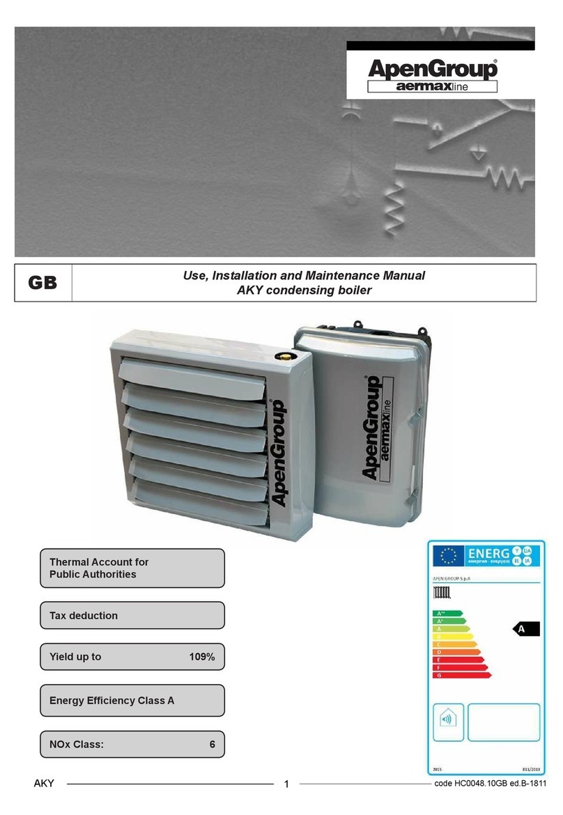
ApenGroup AQUAKOND AKY Manual

GB Installation, Commissioning, and Maintenance Manual
Condensation Boilers AKY
1code HC0048.01GB ed.B-1406
AKY
Efciency Class: ****
NOx Class: 5
Efciency rate up to 109%

CONDENSATION BOILER AQUAKOND AKY
2
code HC0048.01GB ed.B-1406 AKY

CONDENSATION BOILER AQUAKOND AKY
3code HC0048.01GB ed.B-1406
AKY
Dichiarazione di Conformità
Statement of Compliance
-
APEN GROUP S.p.A.
20060 Pessano con Bornago (MI) - ITALY
Via Isonzo, 1
Ph. +39.02.9596931
Fax +39.02.95742758
Website: http://www.apengroup.com
Il presente documento dichiara che la macchina:
With this document we declare that the unit:
Modello/Model: caldaia con aerotermo ad acqua AKY,
Boiler with water Heater AKY,
è stata progettata e costruita in conformità con le disposizioni delle Direttive Comunitarie:
has been designed and manufactured in compliance with the prescriptions of the following EC Directives:
Direttiva macchine 2006/42/CE
Machinery Directive 2006/42/EC
Direttive Apparecchi a Gas 2009/142/CE (ex 90/396/CE)
Gas Appliance Directive 2009/142/CE (formerly 90/396/EC)
Direttiva compatibilità elettromagnetica 2004/108/CE
Electromagnetic Compatibility Directive 2004/108/CE
Direttiva Bassa Tensione 2006/95/CE
Low Voltage Directive 2006/95/EC
Direttiva Erp 2009/125/CE
Erp Directive 2009/125/EC
Qualora la macchina dovesse essere integrata in un impianto (macchine combinate), il costruttore declina ogni
responsabilita se prima, l'impianto di cui farà parte non verrà dichiarato conforme alle sopracitate disposizioni
(Allegato IIB della Direttiva Macchine).
If the unit is to be installed into an equipment (combined), the manufacturer disclaims any responsibility if this
equipment is not previously declared compliant with the requirements specied in IIB Enclosure of above said
Machinery Directive.
Pessano con Bornago
Apen Group S.p.A.
The General Manager
CODE SERIAL NUMBER

CONDENSATION BOILER AQUAKOND AKY
4
code HC0048.01GB ed.B-1406 AKY
3.7 Approval Certicate

CONDENSATION BOILER AQUAKOND AKY
5code HC0048.01GB ed.B-1406
AKY

CONDENSATION BOILER AQUAKOND AKY
6
code HC0048.01GB ed.B-1406 AKY
TABLE OF CONTENTS
SECTION 1. GENERAL WARNINGS 7
SECTION 2. SAFETY WARNINGS 7
2.1 Fuel 7
2.2 Gas Leaks 7
2.3 Power Supply 8
2.4 Use 8
2.5 Maintenance 8
SECTION 3. TECHNICAL FEATURES 9
3.1. Models and Efciency 9
3.2. Data Sheet 10
3.3. Features of Hydraulic System 14
3.4. Ispesl Components 15
3.5. Boiler Dimensions 16
3.6. Operation and accessories 17
SECTION 4. USER'S INSTRUCTIONS 18
4.1. Operation of the Boiler 18
4.2. Control Panel 19
SECTION 5. INSTRUCTIONS TO THE INSTALLER 21
5.1 General Installation Rules 21
5.2. Transport and Handling 21
5.3. Installation Accessories 21
5.4. Installation of Boiler and Blower 21
5.5 Electrical Wiring 23
5.6. Gas Connections 25
5.7 Stack Piping 26
5.8. Filling the Hydraulic System 29
SECTION 6. INSTRUCTIONS TO SERVICE STAFF 30
6.1 Country Table - Gas Category 30
6.2 Gas Setting Data Table 31
6.3 First Start-up 32
6.4 Combustion Analysis 32
6.5 Conversion to LPG 33
6.6. Replacing the Gas Valve and Setting the Offset 33
6.7 Replacing the Modulation Board 34
6.8. Conguring with LCD Display 34
6.9 Maintaining the Exchanger 35
SECTION 7. MODULATION BOARD PARAMETERS 36
SECTION 8. LOCK ANALYSIS - FAULT REPORTING 38
SECTION 9. WIRING DIAGRAMS 40
9.1. Electrical Wiring for AKY032/034/050/070 41
SECTION 10. SPARE PART LIST 42

CONDENSATION BOILER AQUAKOND AKY
7code HC0048.01GB ed.B-1406
AKY
1. GENERAL WARNINGS
This manual is an essential component of the product and must
always accompany it.
If this equipment is sold or transferred to another owner, make
sure the manual follows it, to enable the new installer/owner
to consult it.
The manufacturer disclaims any liability (under contract provi-
sions or otherwise) for damage to persons, animals, or objects
resulting from wrong installation or misuse, and/or non compli-
ance with the manufacturer’s instructions.
This unit is intended only and exclusively for the use for which
it has been built. Any different, wrong, or unreasonable use is
to be considered improper and therefore dangerous.
For the installation, the operation and the maintenance of the
unit, the user shall strictly follow the instructions stated in this
manual.
Any installation, maintenance or servicing operations shall be
performed only by authorized personnel, with specic techni-
cal skills in the heating eld.
Any maintenance operations shall be carried out in compliance
with national laws of the Country where the appliance is installed.
The unit is covered by a guarantee whose conditions and validity
are specied on the relevant certicate.
The manufacturer declares that the unit is workmanlike built in
compliance with UNI, UNI-CIG, and EC technical provisions,
and according to the relevant laws and to the Directive on Ap-
pliances burning gaseous fuels 2009/142/EEC.
2. SAFETY WARNINGS
The following symbol is used in this Manual whenever it is
necessary to draw the operator’s attention on a safety issue.
Safety rules for users or operators
of the equipment and for nearby workers.
This section contains safety rules to be followed for installation
room and ventilation opening.
2.1. Fuel
Before starting the unit, check that:
• Gas supply specications match those written on the rating
plate;
• Combustion air inlet pipes and ue discharge pipes are
exclusively those specied by the manufacturer
• The gas seal of the feeding system has been tested and
approved in compliance with the law.
• The boiler's fuel is the one specied for the unit
• The unit is correctly sized to match required ow and includes
all safety and control devices required by the law;
• Gas pipes have been properly cleaned;
• Fuel rate of ow matches boiler's rated input;
• Gas feeding pressure matches values on rating plate.
2.2. Gas Leaks
If you smell gas:
• Do not operate electric switches, the telephone or any other
object or device that can cause sparks.
• Immediately open doors and windows to vent the room.
• Close gas valves.
• Call for qualied personnel.

CONDENSATION BOILER AQUAKOND AKY
8
code HC0048.01GB ed.B-1406 AKY
2.3. Power Supply
The heater shall be properly wired to an efcient grounding
system, complying with the laws of the Country where the ap-
pliance is installed.
Warning
• Check the efciency of grounding system with the help of
qualied personnel.
• Make sure network wire gauge suits the unit rated input
shown on rating plate and in this Manual.
• Keep neutral wire separate from phase wire. The unit can
be plugged into mains using a plug-socket only if the latter
prevents any mix up of phase and neutral wires.
• The system wire gauge in general, and cable section in
particular, must suit the unit rated input shown on equip-
ment data plate and in this Manual.
• Keep cables and wires away from heat sources.
Important: A multi-pole power switch with a switch-contact
gap of at least 3 mm should be installed before the sup-
ply cable. The switch must be in a visible and accessible
position and within 3 meters from the unit. Any installation
or maintenance operation concerning the electrical system
must be accomplished by qualied personnel.
2.4. Use
Children and inexperienced people shall not be allowed to use
any electrical appliance.
The following precautions shall be adopted:
• Do not touch the unit with wet or damp parts of the body
• and/or barefoot;
• Do not use gas pipes to ground electric devices;
• Do not touch hot surfaces of the unit, such as ue pipes;
• Do not put any objects on the unit;
• Do not touch moving parts of the unit.
2.5. Maintenance
Before running any servicing or cleaning, disconnect power and
gas supply by means of main ON/OFF switch and/or appropri-
ate detection devices.
In case of failure and/or insufcient running standards, switch
off the unit and do not attempt to repair it yourself. Contact the
local authorized Service Centre.
Only use original spare parts for repairs. Failure to follow above
instructions could compromise the unit safety and shall void
the warranty.
If the unit is not used for long periods, shut the gas off through
gas cocks and disconnect the unit from power supply.
If the unit is to be denitively decommissioned, in addition
to above suggestions, any potential source of hazard shall
have to be made inoffensive.
Warning: To properly and safely
operate the equipment, glycol shall
be added to water in the hydraulic circuit in
required percentage according to minimum
temperatures reached in the installation
area.
DO NOT permanently connect circuit inlet
to water mains.
For its AKY boilers,Apen Group tested and recommends
ALPHI 11 glycol manufactured by Fernox. The following
kits can be ordered:
code content
C07200-05 5 litres
C07200-25 25 litres
Safety and health guidelines for the use of
glycol
If ingested in high quantity, glycol can central
nervous system depression, kidney and
liver injury and respiratory problems. Avoid
contact with skin and eyes and protect upper
respiratory tract.
Avoid release to the environment since glycol
can pollute surface and underground water
and the soil.
Wear rubber gloves and boots and standard
protective clothes. Wear safety glasses.
For more information, read safety sheet by
Cookson Electronics, Alpha Metals S.p.A.,
Via Ghisalba 1, 20021 Bollate (Italy)
Ph: +39.02.383311 Fax: +39.02.38300398
email: fernox_italy@cooksonelectronics.
com www.fernox.com

CONDENSATION BOILER AQUAKOND AKY
9code HC0048.01GB ed.B-1406
AKY
3. TECHNICAL FEATURES
AKY condensation boilers burn natural gas or LPG. They are
designed to meet heating requirements in industrial and com-
mercial buildings.
The system’s combustion circuit is built into the boiler. Thus,
neither gas feeding line nor ue exhaust (B23P type in standard
layout) run into the room to be heated.
The equipment works as a standalone unit. In order to start
it up, you only need to connect it to power and gas supplies.
The boiler includes an electrically-operated antifreeze device.
In case of power failure, the system must be lled with a water-
glycol mixture. The glycol percentage varies according to outdoor
temperatures (for more information, see below in this Manual).
At delivery, in AKY032 and AKY034 models when lled with a
mixture of water and 30% glycol. The antifreeze liquid protects
the equipment from temperatures as low as -15°C.
In AKY050 and AKY070 model, the expansion vessel cannot
contain the entire volume of required water-glycol mixture.
Therefore, the antifreeze liquid is not pre-lled.
Boiler construction complies with manufacturing requirements
for gas-red appliances with ratings below 70 kW (EN483).
Condensation and premix technology, combined with ame
modulation, allow reaching efciency levels higher than 108%.
The stainless steel exchanger of the boiler guarantees high
levels of efciency and corrosion resistance.
The burner is entirely built with stainless steel, and it takes ad-
vantage of special mechanical solutions to guarantee optimal
reliability and performance rates, as well as high thermal and
mechanical resistance.
Different types of remote controls, supplied on demand, allow
the user to set and monitor working parameters, such as room
temperature, on/off schedule, operating mode and faults.
Intrinsic Safety
Asophisticated technique of air/gas mixing and the simultaneous
adjustment of combustion air and gas ows provide an increase
in efciency at minimum output.
This technique makes the unit safer since the ratio between
the gas ow through the gas valve and the air ow always
corresponds to the manufacturer's setting. As opposed to
atmospheric burners, in premix units the CO2content does not
change throughout the operative range of the boiler. This allows
higher efciency at lower heat output.
If combustion air fails, the gas valve shuts. If combustion air
decreases, the valve automatically reduces gas ow maintaining
optimal working parameters.
Low Pollution
Pre-mix burners equipped with an air/gas valve allow "clean"
combustion with very low polluting emissions.
3.1. Models and Efciency Rates
AKY boilers are condensation equipment with modulation burner.
Two boiler series are available:
- 00X0 series
Boiler AKY032IT-00X0
- Standard series
Boilers AKY034IT, AKY050IT, AKY070IT
Both series include condensation boilers with 4-star efciency
rate.
00X0 series features:
- Working water temperature = 80/55°C
- Circulator with xed speed and ow rate
Standard series features:
- Working water temperature = 72/45°C
- Efciency levels at maximum output greater than 100%
- Varying speed, low consumption electronic circulator
The following control devices can be used on boilers of both
series: remote control, SmartControl or SMART.NET.
SmartControl and SMART.NET allow simultaneous control of
00X0 and standard boilers.
Standard boilers are designed for reaching efciency levels
above 100% on LHV (lower heating value) at maximum thermal
output, and of 108% at minimum thermal output.
Boiler efciency rates with delivery water temperature of 72°C
are certied.
Using SmartControl or SMART.NET optional devices, the
“room compensation” feature can be enabled. Delivery water
temperature can thus be reduced in an inversely proportional
ratio to room temperature increase, reaching efciency levels
of the boiler over 108% [Hi].
The exchanger installed intoAKY boilers helps further reductions
of heat losses of the casing and enhances efciency.

CONDENSATION BOILER AQUAKOND AKY
10
code HC0048.01GB ed.B-1406 AKY
3.2. Data Sheet
* Standard boiler includes terminal for B23P layout. Other layouts can be created using suitable accessories.
** When working with a blower, return temperature is below 60°C. Expected efficiency will therefore be higher than v a l u e
indicated. In water efciency value, also ue condensate is considered.
** Efciency at minimum capacity refers to using the boiler with 30% load in compliance with EN483/A2 and EN677 standards.
*** CO and NOx values refer to the weighted average of minimum and maximum heat output values with dry ue.
Boiler - Series 00X0 AKY032-00X0
HC00046 ET 012
Type of appliance B23P*-B53P-C43-C53-C63-C83
EC Approval P.I.N. 0694BT1623
Efciency class [Hi] [EC 92/42 Directive] ****
NOx Class [EN 483] 5
Boiler efciency
MAX MIN
Combustion Chamber Heat Output [Hi] [75/55°C] kW 31.0 5.0
Useful heat output for water [Hi] [75/55°C] ** kW 30,1 5.3
Useful heat to water [Hi] [80/60°C] ** % 96.5 96.7
Useful heat to water [Hi] [75/55°C] ** 97,1 106,0
Useful heat at 39% of load [Hi] [50/30°C] % 104.5 107.3
Stack loss with burner on [80/60°C] ** % 3.7 1.4
Stack loss with burner off % 0.1
Enclosure loss [average T=60°C] % 0.40
Condensate max quantity l/h 0.8
Flue - Polluting emissions
Carbon monoxide - CO - [0% of 02] ppm 44 ppm ***
Nitrogen oxide - NOx - [0% of 02] 18 pmm - 31mg/kWh ***
Flue Temperature °C 75 48
Pressure available at stack Pa 90
Electric Data
Supply Voltage V 1 Phase 230V-50 Hz
Power rating W 160
Running Temperatures °C -15°C to +50°C
Protection Class IP IPX5D
Hydraulic connections
Max running pressure bar 3
Water content of the boiler l 4.5
Delivery/return ttings - UNI ISO 7/1 - Ø G 3/4" M
Gas tting Ø G 3/4" M
Weight at work (water included) kg 32
Weight with packaging kg 37

CONDENSATION BOILER AQUAKOND AKY
11 code HC0048.01GB ed.B-1406
AKY
* Standard boiler includes terminal for B23P layout. Other layouts can be created using suitable accessories**
** In water efciency value, also ue condensate is considered.
** Efciency value with water 80/60 is shown as an info for system designer.
**Efciency at minimum capacity refers to using the boiler with 30% load in compliance with EN483/A2 and EN677 standards.
***CO and NOx values refer to the weighted average of minimum and maximum heat output values with reference to ue.
BOILER - Standard series AKY034 AKY050 AKY070
HC00046 ET 012
Type of appliance B23P*-B53P-C43-C53-C63-C83
EC Approval P.I.N. 0694BT1623
Efciency class [Hi]
[EC 92/42 Directive] ****
NOx Class [EN 483] 5
Boiler efciency
MAX MIN MAX MIN MAX MIN
Combustion chamber heat output [Hi] [72/45°C] kW 34.8 8.0 49.0 8.1 65.0 11.0
Useful heat to water [72/45°C] kW 35.2 8.6 48,9 8,2 65.3 11.8
Useful heat to water [Hi] [50/30°C]** % 105.8 108.9 104.8 105.5 104.5 107.4
Output to water [Hi] [72/45 °C] ** % 101.1 107.5 99.7 100.8 100.5 107.5
Useful heat to water [Hi] [80/60°C] ** 98.3 96.8 95.7 97.5 97.4
Stack loss with burner on [72/45°C] ** % 2.6 1.4 2.7 1.0 2.7 0.9
Stack loss with burner off % 0.1
Enclosure loss [average T=60°C] % 0.35 0.40 0.40
Condensate max quantity l/h 0.8 1,6 2.2
Flue - Polluting emissions
Carbon monoxide - CO - [0% of 02] ppm 43 ppm *** 30 ppm *** 44 ppm ***
Nitrogen oxide - NOx - [0% of 02] 31 ppm - 55 mg/kWh ***15 ppm - 27 mg/kWh ***36 ppm - 64 mg/kWhh
***
Flue temperature °C 75 48 75 40 75 40
Pressure available at stack Pa 90
Electric Data
Supply voltage V 1 Phase 230V-50 Hz
Power rating W 128 143 45 183 29
Running temperatures °C -15°C to +50°C
Protection class IP IPX5D
Hydraulic Connections
Max running pressure bar 3 2,7
Water content of the boiler l 5.0 6,3 7.0
Delivery/return ttings - UNI ISO 7/1 - Ø G 3/4" M G 1" M G 1" M
Gas tting Ø G 3/4" M
Weight at work (water included) kg 35 45 47
Weight with packaging kg 40 43 45

CONDENSATION BOILER AQUAKOND AKY
12
code HC0048.01GB ed.B-1406 AKY
Boiler technical data
Available Head-Flow Rate Curve for Boilers
Required water ow rates in the AquaKond boilers are the following:
• 32 Flow rate from 900 to 1,300 l/h;
• 34 Flow rate from 1,000 to 1,400 l/h;
• 50 Flow rate from 1,600 to 2,000 l/h
• 70 Flow rate from 2,000 to 2,400 l/h;
The boiler can normally work also with lower ow rates. In such case, to reach maximum thermal output, you need to increase
delivery temperature and, consequently, heat drop.
0
10
20
30
40
50
60
70
80
0 500 1000 1500 2000 2500
prevalenza (KPa)
Portata (l/h)
Curva Prevalenza disponibile/Portata acqua per Caldaie serie AKY
AKY050
AKY034
AKY032
AKY070
Available Head-Flow Rate Curve for Boilers AKY
Flow Rate (I/h)
Head
(KPa)

CONDENSATION BOILER AQUAKOND AKY
13 code HC0048.01GB ed.B-1406
AKY
Duct pressure losses
The table below shows pressure loss in ducts by ow rate multiple values.
Losses are measured in kPa per 1 meter of pipe length. Measure to be considered is the equivalent length of the hydraulic circuit.
Losses are calculated for water at 70-75°C without glycol. If glycol is added to the water, losses should be multiplied by the given
factor. The volume in litres for 1 meter of pipe is reported in the last line.
Value of pipe length losses should be summed to spot pressure losses due to components of hydraulic system according to the
following table.
Ratios for Glycol
The table below shows freezing temperatures for water-glycol mixture.
If such uid is used, pressure losses need to be increased using the following ratios:
• If glycol is 10% of the volume, multiply by 1.07
• If glycol is 20% of the volume, multiply by 1.15
• If glycol is 30% of the volume, multiply by 1.22
APEN GROUP recommends for its AKY boilers the use of mixtures of water and monopropylene glycol FERNOX ALPHI11.
Different types of glycol might void the warranty.
Losses are measured in kPa per 1 meter of pipe length
Water ow rate Steel tubes Copper tubes
l/h 3/4" 1” 1"1/4 1"1/2 2” 20/22 25/28 32/35 39/42 51/54
600 0.15 0.05 0.18 0.06 0.02
900 0.31 0.10 0.03 0.35 0.12 0.04
1,200 0.55 0.18 0.05 0.02 0.60 0.20 0.07 0.03
1,500 0.82 0.26 0.07 0.03 0.30 0.10 0.04
1,800 0.36 0.10 0.04 0.01 0.42 0.13 0.05 0.01
2,100 0.49 0.13 0.06 0.02 0.52 0.17 0.07 0.02
2,400 0.65 0.16 0.08 0.03 0.70 0.21 0.09 0.03
3,000 0.24 0.11 0.04 0.27 0.12 0.04
3,600 0.34 0.16 0.06 0.35 0.17 0.06
4,200 0.45 0.21 0.07 0.53 0.22 0.07
4,800 0.59 0.21 0.08 0.28 0.08
Water content l/m 0.37 0.59 1.20 1.39 2.22 0.31 0.49 0.80 1.19 2.04
Equivalent length in meters Steel tubes
3/4" 1” 1"1/4 1"1/2 2”
Bend 45° 0.3 0.3 0.6 0.6 0.6
Bend 90° 0.6 0.6 0.9 1.2 1.5
90° bend wide radius 0.6 0.6 0.6 0.6 0.9
T joint 1.5 1.5 1.8 2.4 3.0
Non return valve 1.5 1.5 2.1 2.7 3.3
Shutter 0.3 0.3 0.3 0.3 0.3
Table of freezing temperatures
% glycol 25 30 35 40
Freezing temperature -11°C -15°C -18°C -22°C

CONDENSATION BOILER AQUAKOND AKY
14
code HC0048.01GB ed.B-1406 AKY
RBC System lling valve
STF Flue temperature sensor NTC
VF Burner fan
TR* Thermometer
TS Safety thermostat 87°C
VE Expansion vessel
VS1 AKY032/034 safety valve
VS2* AKY050/070 safety valve
VSC Boiler vent valve
TERM* ISPESL thermometer
* For AKY050/070 models only
Legend
U.E. Outdoor unit (boiler)
EV1 Primary gas solenoid valve
EV2 Secondary gas solenoid valve
FLUX Water ow meter
IDROM* Hydrometer
IPMAX* Water limit pressure switch [manual reset]
IPMIN* Minimun water pressure switch [manual reset]
NTC Modulation temperature sensor
PDIFF Differential pressure switch (water ow switch)
PI System pump (circulator)
PIT* Well for temperature check
PMIN Water minimum pressure switch
PZI* Housing for fuel shut-off valve
R3VIE* Three-way control valve
EV1EV2
STF
U.E.
HC0047 C2 034
3.3. Features of the Hydraulic System
Hydraulic systems of AKY boilers are similar. However, AKY050/070 boilers have some additional components if compared to
AKY032/034 models.
If more than one boiler is installed, you only need to sum their heat output values when the hydraulic circuit is shared
by multiple boilers.

CONDENSATION BOILER AQUAKOND AKY
15 code HC0048.01GB ed.B-1406
AKY
3.4. ISPESL COMPONENTS
SAFETY, CONTROL AND PROTECTION DEVICES
Component Code Model Description
Hydrometer ID PB3204BB06 Manometer class UNI2.5, range 0-4bar
WATTS INDUSTRIES pmax, ex.+25% f.s., T=-20/90°C ISPESL-compliant
Limit pressure switch IPMAX PMR/5-R2 Pressure switch p=1-3bar
ITALTECNICA ISPESL-compliant certicate N° PS/001/10
Inspection well PIT PGUA0TT003 Control well L=45mm, tting 1/2"
WATTS INDUSTRIES ISPESL-compliant
Control three-way cock RB 403R14 Three-way cock, tting 1/4",
WATTS INDUSTRIES Tmax, ex=90°C, Pmax, ex=15bar ISPESL-compliant
Thermometer TER PT4A507011 Fitting 1/2" with well
WATTS INDUSTRIES T=0/120°C precision class UNI 2, ISPESL-compliant
Expansion vessel VE 13S6001006 10 l. capacity, tting 3/4",
default charge 0.75bar
WATTS INDUSTRIES Tmax, ex.=90°C, Pmax, ex.=15bar ISPESL-compliant
Safety valve VS 527427 Fittings 1/2"Fx3/4"F, adjusted 2,7 bar, diameter 15 mm,
CALEFFI discharge capacity 152.2 kW. Tmax=110°CV
ISPESL APPROVAL CERTIFICATE N°VS/319/00
Safety thermostat TS 1NT08L NC terminal of thermostat, opening T=87±4°C
Sensata Tes=-20/+180°C,
KEMA certicate 2014531.16
NOTE: Test on Water Circuit
ISPESL standards require that the boiler body is tested at a pressure of 4.5 bars, i.e. one and a half times its maximum working
pressure.
NOTE: Distance between expansion tank and safety valve [only AKY050/070].
According to ISPESL standards, the distance between the vessel centerline and the safety valve centerline is 450 mm.
NOTE: Fuel detection valve [AKY050/070 only].
ISPESL standards mandatorily require the installation of a fuel detection valve on appliances over 35 kW. In designing the boiler,
Apen Group envisaged the possibility to add a well for inspecting the fuel detection valve. Relevant kit has the code C09073.
NOTE: Expansion vessel
All boilers include an expansion vessel with 10 l. capacity, pre-loaded at 0.75 bars.
When system capacity exceeds 95-100 litres, an expansion vessel with suitable capacity shall be installed.
Water contents of boilers are summarized in the table below. For information on pipes, see page 16 of this Manual.
WATER CONTENT
Boiler AKY032 3.5 l
Boiler AKY034 4.0 l
Boiler AKY050 6.3 l
Boiler AKY070 7.0 l

CONDENSATION BOILER AQUAKOND AKY
16
code HC0048.01GB ed.B-1406 AKY
500
755
HC0047 C2 002
455
AKY050/070
310
10
8
9
4
2 6 3 7 5 1
AKY032/034
AKY032/034 AKY050/070
3.5. Dimensions of Boilers
Description Dimension
032/034 050/070
1 GAS SUPPLY G3/4"
2 WATER RETURN G3/4" G1"
3 WATER DELIVERY G3/4" G1"
4SAFETY VALVE G1/2"
5SAFETY VALVE G3/4"
6 SYSTEM FILLING VALVE G1/2"
7 CONDENSATE DRAIN Ø14 mm
8 WIRING PG 09
9FUEL DETECTION VALVE Ø14mm
10 FLUE-GAS STACK 60 mm

CONDENSATION BOILER AQUAKOND AKY
17 code HC0048.01GB ed.B-1406
AKY
Boiler ON/OFF switchr
Reset button
Lock
alert
lamp
3.6. Operation and Accessories
The boiler includes a standard
LCD multifunction panel that
enables the user to manage,
setup and diagnose all the op-
erating parameters of the unit.
See paragraph “LCD panel”
for more info.
This panel cannot be remotely
controlled.
Room Temperature Setup
The boiler is delivered with no remote control nor room thermo-
stat. You can order a remote control to APEN GROUP or buy
it from your supplier.
Working modes:
A) basic thermostat, or chronothermostat, with one free digital
contact for wiring to ID2/IDC2 terminals of the boiler;
B) SmartControl code G20800IT;
C) SMART.NET application G16900-USB.
This Manual provides information on AquaKond systems of
“A” type. For more information on the use of SmartControl and
SMART.NET, see relevant manuals.
Main functions
The appliance features:
• Antilock system of varying speed circulator
• Antifreeze
Operation Mode A: Simple Remote Control
The customer installs a chronothermostat or a room thermostat
with a free contact between ID2/IDC2 terminals. By opening or
closing this contact the boiler is turned off or on. Modulation
concerns delivery water, whose temperature remains steady at
default value (72 or 80°C, based on the series) If more room
units are connected and one of these is turned off, the boiler
automatically reduces output without decreasing water tem-
perature. Lock and reset alerts available on the boiler can be
transferred to remote control if APEN control C09660 is used.
Operation Mode B: SmartControl Chronothermostat
(G20800IT)
This chronothermostat can be used in a system to control one
zone where the units installed range from 1 to 30. The units
work at the same temperature and only one control is needed.
Also, room temperature and schedule must be the same for
the entire zone.
This chronothermostat has a bright, easy-to-read OLED display.
It allows setting up and monitoring any parameters of connected
units, either in automatic or manual mode, verifying burner
operation, planning weekly or yearly schedules and managing
daily ON/OFF periods.
Operation mode D: SMART.NET application (G16900-USB)
This mode requires using SMART.NET application, a computer,
and one or more room sensor for each area or building to control.
This application is recommended if the number of installed units
exceeds 5. It offers a comprehensive overview of the entire
system and allows to reset the units directly from your computer.
Fault notications can also be sent by text message or email.
See SMART.NET manual for more information.

CONDENSATION BOILER AQUAKOND AKY
18
code HC0048.01GB ed.B-1406 AKY
Boiler ON/OFF switchr
Reset button
Lock
alert
lamp
Remote control C09660
4. USER'S INSTRUCTIONS
Read General and Safety Warnings on page 6. Users shall
only use commands on remote control or room devices.
4.1. Operation of the Boiler
Boiler operation is completely automatic. An electronic self-
checking device handles any control operations of the burner
while an electronic board with built-in microprocessor regulates
thermal output power.
This section describes a boiler with no accessories. To learn
more about operation with SmartControl and SMART.NET,
please refer to relevant manuals.
Heating request causes the unit to start when the following
conditions are met:
• The boiler is powered and not locked.
• The contact on terminals ID2/IDC2 of the boiler’s electronic
board is closed.
In these conditions, the circulator and the burner fan start im-
mediately. After pre-washing time, the ame lights up at a ring
power of about 50% of maximum power. Once the ame is
stabilized, the burner starts modulating based on delivery water
temperature set point, which is 72°C for standard boilers and
80°C for 00X0 boilers.
If the ame fails during start-up, the ignition cycle is repeated
4 times, then the boiler locks.
The boiler turns off when ID2/IDC2 contact opens. Except for
emergencies, DO NOT power off the boiler since the circulator
keeps working for 3 to 5 minutes after the boiler stops as well
as the ue fan (25 seconds) to cool down the unit and clean
the combustion chamber.
4.1.1. Setting Room Temperature
A room thermostat or chronothermostat or an ON/OFF switch
must be wired to the boiler.
If a third party thermostat is installed, room temperature must
be set on the thermostat.
This kind of installation requires a remote control (code
C09660) to enable the user to check locks and remotely
reset the boiler, if necessary, without inspecting the boiler
outdoor.
4.1.2. Lock and Reset Messages
A red lamp on C09660 remote control alerts the user when a
problem occurs.
The red lamp only warns about the existence of the problem
but gives no indication about its nature. The reset button is right
under the lamp.
Error codes from F01 to F99 are shown on the display inside
the boiler and/or on SmartControl or SMART.NET, if applicable.
To reset the boiler, press simultaneously both arrows on LCD
panel inside the boiler.
See below for a list of error codes.
4.1.3. Setting Boiler Temperature
The boiler is supplied with a ST1 default (delivery temperature
water) set to 72°C for standard oilers and to 80°C for 00X0
boilers. This parameter can be changed on LCD panel on the
boiler or using SmartControl or SMART.NET.
4.1.4. Antilock System of Varying Speed Circulator
This feature, enabled by default, starts the circulator after 24
consecutive hours of non operation. The circulator works for
120 seconds, then stops.
You can disable this feature using d1 parameter from remote
control, SmartControl, or SMART.NET.
The circulator speed changes based on output thermal power.
Minimum speed is used depending on the value set in two
parameters.
4.1.5. Antifreeze
This feature is disabled by default since the manufacturer
recommends lling the circuit with a mixture of water and gly-
col. However, this feature has a two-stage operation. If water
temperature decreases below the rst threshold, a circulator is
activated to circulate the water into the system. If the temperature
decreases below the second threshold, the burner is turned on
to heat the water in the system.
To enable this feature, change the value in Parameter d8=1
using the LCD display on the boiler.

CONDENSATION BOILER AQUAKOND AKY
19 code HC0048.01GB ed.B-1406
AKY
4.2.2. Navigation Menu
The menu has three levels: the rst requires no password while
for the second and third, a password is required.
If the boiler board is connected to a SmartControl and/or to
SMART.NET and the address is different from 0, parameters
are read-only and cannot be changed and some menus are
not available.
When Service Staff need to access all menus, they will have
to do the following:
- Disconnect the unit from power supply.
- Set the board address to 0
- Restore power supply.
- When done, remember to restore switches to their original
position.
To scroll menus, use UP and DOWN arrows. Press ENTER
to select the menu or the parameter. To change a parameter
value, use UP or DOWN arrows, then press ENTER to conrm.
Press ESC to quit. After 10 minutes from last entry, setup mode
automatically closes and the standard status display is restored.
Use arrow keys to change the parameter (UP arrow to increase
and DOWN arrow to decrease). If you keep the arrow pressed,
the speed increases.
To conrm the change, press ENTER for at least 3 seconds.
The display ashes to conrm the parameter was changed.
All submenus scroll from bottom to top.
4.2.3. 1st Level Menu
1st level menu includes:
1. Status: ON, rdy, OFF
2. FUn: this parameter forces ON/OFF operation. This menu
can be accessed only if the equipment runs in standalone
mode (ModBus address = 0).
3. rEg: forces the burner to minimum (Lo) or maximum (Hi)
power output. It is used for combustion tests. This parameter
too is active only when modbus address = 0.
4. tin: shows input tension value (0/10Vdc) when boiler is
connected to a controller for cascade handling.
5. PrA: shows water pressure in the circuit. It is used when
lling the system and checking the pressure in the boiler
and the hydraulic circuit. If 01.6 is displayed, the pressure
in the circuit is 1.60 bars.
6. Abi. From Abi menu, you can access submenus using
second and third level passwords.
Note: To view water pressure value, press Enter when
Pra is displayed.
4.2. Control Panel with LCD Display
The control panel includes an three-digit LCD with four function
keys: ↑, ↓, ESC and ENTER;
This display allows
the user to monitor
boiler operation,
faults, water pres-
sure in the hydraulic
circuit and sensor
detected values.
It can also be used
by Service Staff to
change main oper-
ating parameters.
Parameter changes
are password pro-
tected.
4.2.1. Viewing the Equipment Status
The status of the equipment is reported on the display through
the following messages:
rdy Means the equipment is powered but there is no ame
lit in the burner. It is waiting for an ON command and/or a heat
request from room temperature control.
On The unit is ON and a ame is lit in the burner;
OFF Means the equipment was turned off using LCD control.
Any heat requests will be ignored. To turn the boiler ON, switch
LCD display to “Operation ON”
Fxx A problem (fault) exists.
During regular operation, the display shows On if the burner is
turned on, or rdy if the burner is turning off or room tempera-
ture is reached.
If a SmartControl and/or SMART.NET are installed, board ad-
dress must be set to a non-zero value. In such case, the modbus
address of the board ashes for 5 seconds on the display as
Axx, where xx is the congured address.
If the CPU-SMART board does not correctly interface with the
LCD display, CPU will ash on the screen if the problem is
with the CPU, or three dots will ash if the problem is with the
display board.
If so, check that the display and the board are properly con-
nected and that the RJ11 cable is rmly plugged in.

CONDENSATION BOILER AQUAKOND AKY
20
code HC0048.01GB ed.B-1406 AKY
4.2.4. Second Level Menu
Second and third level menus are reserved to Service Staff and
are password protected.
4.2.5. Error Code List
If the boiler locks, its board reports the problem using an error
code.
To unlock the boiler, press the 2 arrow keys together for at least
3 seconds or use the remote control, if installed.
Errors are ranked by type. The most common ones can be
repaired by the user and are the following:
F1x The burner did not start. Manual reset is required.
F20 Safety thermostat of the boiler has locked. Manual reset
is required.
F21 Lock of boiler thermal cut-out and, only for AKY050/070,
of max pressure regulating valve. Replace thermal cut
out for the rst case, and manually reset the regulating
valve for the second one.
F3x Locks due to problems with ue fan or burner.
F4x Locks caused by lack or failure of a temperature sensor.
Call Service Staff.
F51 Water temperature in the boiler exceeded the threshold
set in TH3 parameter. When temperature decreases,
the lock is automatically removed. No manual reset is
required.
F53 Similar to F51 but concerns ue temperature.
F60 Only on LCD panel. The boiler is controlled through
SmartControl or SMART.NET but communication failed.
When communication is restored, the lock is automati-
cally removed. No manual reset is required.
F80 Lack of water in the circuit. Rell the boiler. Normal PrA
value must be higher than 50 (0.50 bars) but lower than
220 (2.20 bars). The lock is automatically removed when
the boiler is full. No manual reset is required
F81 Water pressure is low but still enough to operate the
boiler. This is a warning to the user. Check water pres-
sure.
F82 Water pressure is too high. This is a warning. The boiler
still works. The problem could be with an excessive lling
of the circuit or the expansion vessel.
F85 No water circulation. Taps are closed or circulator failed.
F86 Water ow in the circuit is lower than set parameters.
Check diameter and length of the pipes or boiler board
parameters.
F90 Flue temperature exceeds expected values. Verify if the
boiler needs cleaning. This lock requires manual reset.
F91 The boiler did not exceed ue temperature threshold but
is reducing thermal output.
4.2.6. Antifreeze Feature
This feature is enabled only on 050/070 model as a precaution
to avoid that the ue intercepting valve triggers at temperatures
around zero. The recommended way to avoid freezing is to ll
the system with a water-glycol mixture. This would protect the
equipment also in case of power black-out.
To enable the antifreeze feature, set d8=1 based on water tem-
perature, on freeze set point and on PA hysteresis The circulator
will start, as well as the burner, if necessary.
When antifreeze feature is enabled, the boiler will do the following:
NTC1>(STA+PA): standby;
NTC1<(STA+PA): water circulation enabled;
NTC1<(STA-PA): water circulation and burner enabled;
Table of contents
Other ApenGroup Boiler manuals
Popular Boiler manuals by other brands

Beretta
Beretta IDRA HP 300 installation manual

Gorenje
Gorenje GBFU50SIM Instructions for use

Viessmann
Viessmann Vitodens 100 WB1 Technical data

Ataq
Ataq Q 25S operating instructions

Viessmann
Viessmann VITOCELL-H 100 Technical data manual

Grant
Grant EFCON5070IND Design, installation and servicing instructions

Ideal Heating
Ideal Heating IMAX XTRA 2 quick start guide

Grant
Grant Vortex VTXBH1521 Installation and servicing instructions

Marco
Marco ECOSMART PB10 instructions

Modulens
Modulens AGC 10 Installation and service manual

LK Systems
LK Systems 11-n Assembly instructions

EHC
EHC Comet Combi 14.4kW Installation & technical manual