Aplus aP23KWC28S User manual

Integrated Circuits Inc.
aP23KWC28S USB Writer User Guide
Page 1 of 33 5/6/2016
aP23KWC28S
USB Writer
USER GUIDE
Aplus Integrated Circuits, Inc.
www.aplusinc.com.tw

Integrated Circuits Inc.
aP23KWC28S USB Writer User Guide
Page 2 of 33 5/6/2016
Introduction
The aP23KWC28S USB Writer is designed to support Aplus aP89K series Voice chips. It is suitable for:
-aP89682K ( 682 sec, 11 I/O chip) – SOP28
-aP89341K ( 341 sec, 11 I/O chip) – SOP28
-aP89170K ( 170 sec, 11 I/O chip) – SOP28
-aP89085K ( 085 sec, 11 I/O chip) – SOP28
This development system serves three main functions:
Compiler – to create a dp2 file from user’s Voice files
Writer – to program the dp2 file into the aP23xxx chip
Copier – connect DC 5V adaptor for 1 to 1 programming
The Compiler is used to combine the edited voice files into the chip to form the desired Voice Group and
to define the playback functions of each Voice Group by selecting different Options and Trigger Modes
of each individual Voice Group.
The Writer is used to program the voice data into the aP23xxx devices that resulted from the Compiler
Function. A Writer Board connected to the PC via USB port is required.
The Copier is using the compiled *.dp2 which loads to writer then disconnect the USB and connect the
DC 5V for 1 pcs copying.

Integrated Circuits Inc.
aP23KWC28S USB Writer User Guide
Page 3 of 33 5/6/2016
Installation
Hardware Installation
aP23KWC28S is a USB based writer programmer. It is intended to be used in Windows XP,Win7,Win8,
Win10 computer.
Writer Board Connection
1) Connect USB cable from the writer board to the computer. The computer will display a new
hardware is found message. The installation will begin automatically.
2) If there are too many USB devices are connected to your computer at the same time, the current
supply from USB may not be sufficient to support the writer board.
Fig. 1 The aP23KWC28S USB Writer Programmer Board

Integrated Circuits Inc.
aP23KWC28S USB Writer User Guide
Page 4 of 33 5/6/2016
Running The Software
Double click the file 23KWComplier.exe to launch the software.
COMPILER :
COMPILER DESCRIPTION:
1. Select your required IC body.
--- aP23682-8pin , aP23341-8pin , aP23170-8pin , aP23085-8pin.
--- aP23682-16pin , aP23341-16pin , aP23170-16pin , aP23085-16pin.
--- aP89682K , aP89341K , aP89170K , aP89085K.
2. Select your required trigger mode.
--- Key mode / CPU parallel mode / MP3 mode / SPI mode / I2C mode / aP89 mode / SBT mode.
3. Select voice output mode.
--- DAC or PWM.
4. Show all your required voice files. (Only wav files acceptable).
--- The [xxx.wav]: 8 bits or 16 bits mono xxx.wav.

Integrated Circuits Inc.
aP23KWC28S USB Writer User Guide
Page 5 of 33 5/6/2016
5. Select the compression mode.
--- ADPCM4 / ULAW8 / PCM8 / PCM16.
6. Select your required voice file [xxx.wav] folder.
7. Select if adding the silence.
--- 1ms ~ 10000ms.
8. Loading the required *.wav files.
9. Setting your required voice sections and function mode.
10. Show your final voice list.
11. Compiler: After setting the voices & function, push the button to create xxx.txt & xxx.dp2 files.
12. Re-download & Re-editing [xxx.dp2] to setting and function.
13. Show the memory of your usage.
14. Show the IC body memory size.
15. Show Check Sum.

Integrated Circuits Inc.
aP23KWC28S USB Writer User Guide
Page 6 of 33 5/6/2016

Integrated Circuits Inc.
aP23KWC28S USB Writer User Guide
Page 7 of 33 5/6/2016
16. Select required debounce time.
--- 65us or 16ms.
17. Select if using low voltage detect.
--- Select ON if the IC voltage less than 2V will be reset.
18. Select if using the oscillator.
--- XT (X’tal=16MHz ) / Rosc ext ( 68K ohm ) / Rosc Int.
19. Select the output function for output1, output2, output3.
--- Busy-H, Busy-L.
--- LED Flash (LED high active ) , ~LED Flash (LED low active ).
--- Stop-H, Stop-L.
--- Prog-BusyH, Prog-BusyL.
--- Load: For the play command [094h+D9~D0]; [D9~D0] total 10 bits indicate the voice address.
Same the aP89341 prefetch-071h [no gap loop play].
Integrated Circuits Inc.
aP23KWC28S USB Writer User Guide
Page 8 of 33 5/6/2016
20. Select PWM voice output volume.
---Select PWM high volume.
21. Select IC operating voltage at PWM (VOUT).
--- Low Voltage: 3V, High Voltage: 4.5V.
22. IC body configures advanced function.
23. Select SBT pin swap. (for 8pin device only).
--- Select (SBT as OUT1) or (SBT as KEY3).
--- SBT as OUT1: Busy-H/L, Stop-H/L, LED Flash (LED high active),
~LED Flash (LED low active), Prog-BusyH/L, Load.
S3 ( pin7 ) S2 ( pin6 ) Group
SBT = OUT1
0 1 SW1 Busy-H/L
Stop-H/L
LED ……
1 0 SW2
1 1 SW3
--- SBT as Key3:
SBT ( pin5 ) S3 ( pin7 ) S2 ( pin6 ) Group
0 0 1 SW1
0 1 0 SW2
0 1 1 SW3
1 0 0 SW4
1 0 1 SW5
1 1 0 SW6
1 1 1 SW7
24. Select power on play.
--- Power on play [sw0] group once.
25. Select SBT loop. (At SBT mode).
--- Enable: The SBT pin sequential trigger & loop play.
--- Disable: The SBT pin sequential trigger & play once.
*Note: Voice function (Trig Level) must select Level.
26. Select volume control function.
--- Select the volume control Level x16 / x8 / x4.
27. SBT pin act play/pause or play/stop function for MP3 mode.
28. Select if using pin S4 as data output pin.
--- The SPI mode or I2C mode of data output for 24 pin IC body and 16 pin IC body.

Integrated Circuits Inc.
aP23KWC28S USB Writer User Guide
Page 9 of 33 5/6/2016
WRITER :
WRITER DESCRIPTION:
1. Loading your programming file. (xxx.dp2)
2. Show setting and function after loading *.dp2 file.
3. Show your required IC body.
4. Show voice sections and function mode.
5. Show the content of your selected section of voice list.
6. Select to blank check IC is blank?
7. Select to execute programming.
8. Select to verify the data of your programming.
Integrated Circuits Inc.
aP23KWC28S USB Writer User Guide
Page 10 of 33 5/6/2016
9. Select if you need security mechanism.
*** (If do this, it can’t be copied; it can’t be Master IC.)
10. Execute your selected (6.) (7.) (8.) (9.).
11. Show the progress of “blank check”, “program”, “verify” and “load to flash”.
12. Load to Flash: download the program file (xxx.dp2) to [1 to 1 copier] writer.
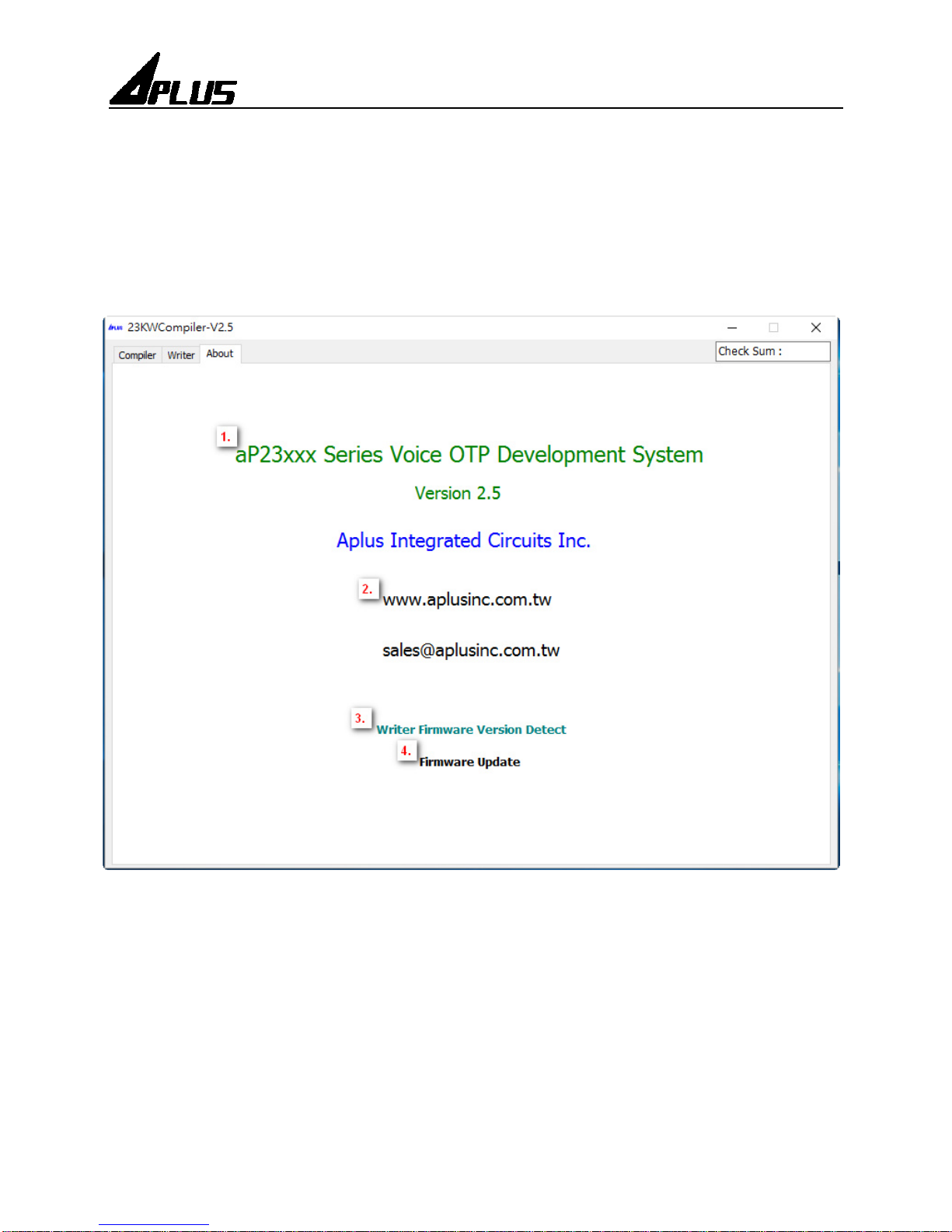
About :
ABOUT DESCRIPTION:
1. Show software version.
2. Show website of Aplus Integrated Circuits Inc.
3. Detect writer firmware version.
4. Update writer firmware version.
This manual suits for next models
1
Table of contents
Other Aplus Motherboard manuals


