QUICK START GUIDE EPC9147C Motor Drive Controller Interface Board
EPC – POWER CONVERSION TECHNOLOGY LEADER | EPC-CO.COM | ©2021 | | 7
EXTRA FUNCTION PORT
The EPC9147C is provided with an extra function port (J2) that can be
used to expand functionality to the board. Table 6 provides the pin
allocation map for the expansion port. The usage of the expansion port
depends on ocial ST rmware. In the demo provided by EPC, these
functions are not used.
QUICK START PROCEDURE
Please check EPC’s EPC9147C product page for updates on compatible
eGaN FET/IC inverters with reference settings for specic motors:
https://epc-co.com/epc/Products/DemoBoards/EPC9147c.aspx
The demo program is set to drive a specic motor: Teknic M-3411P-LN-08D.
If a dierent motor needs to be used, please follow these steps:
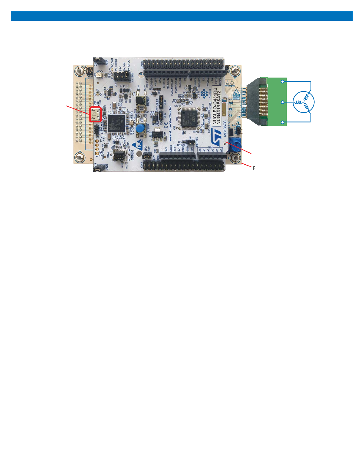
1. Verify that the ST Nucleo G431RB is properly mounted on the EPC9147C
as shown in Figure 2.
2. Verify that on ST Nucleo board, CN11, CN12, JP6, and JP3 jumpers are
mounted. JP8 must be in position 2-3, 5V_SEL must be in 5V_STLK
position, and JP1 and JP7 are not mounted.
3. Connect the motor Teknic M-3411P-LN-08D to the power board. Only
the three phase wires of the motor are needed, because the rmware
is sensor-less.
4. Connect 48 V 3.0 A power supply to the power board connected to the
EPC9147C.
5. Power up the 48 V power supply.
6. Press the black button once.
7. Press the blue button once. Motor start spinning at a xed speed.
8. Press the blue button once again. Motor Stops.
Warning: The human interface controls and knob, as well as the
entire EPC9147C, and the ST Nucleo board are not isolated. The
EPC9147C is referenced to Power Ground and extreme caution must
be observed when operating the board at high voltage.
Table 6: Extra Function port (J2) pin allocation map
Pin # Connector
15 V
2 GND
3 PFC shutdown
4 PFC iL
5 ICL shutout
6 PFC PWM
7PFC Vac
8 PFC Synce
MOTOR COMMISSIONING PROCEDURE
To commission a new motor, the user must install the entire development
suite from ST website after registration.
Download and install the following programs:
ST Motor Control Workbench:
https://www.st.com/content/st_com/en/products/embedded-
software/mcu-mpu-embedded-software/stm32-embedded-software/
stm32cube-expansion-packages/x-cube-mcsdk.html
STM32CubeMX
https://www.st.com/en/development-tools/stm32cubemx.html
STM32CubeIDE
https://www.st.com/en/development-tools/stm32cubeide.html
For your reference, the page about the ST Nucleo G431RB is at this link:
https://www.st.com/en/evaluation-tools/nucleo-g431rb.html#tools-
software
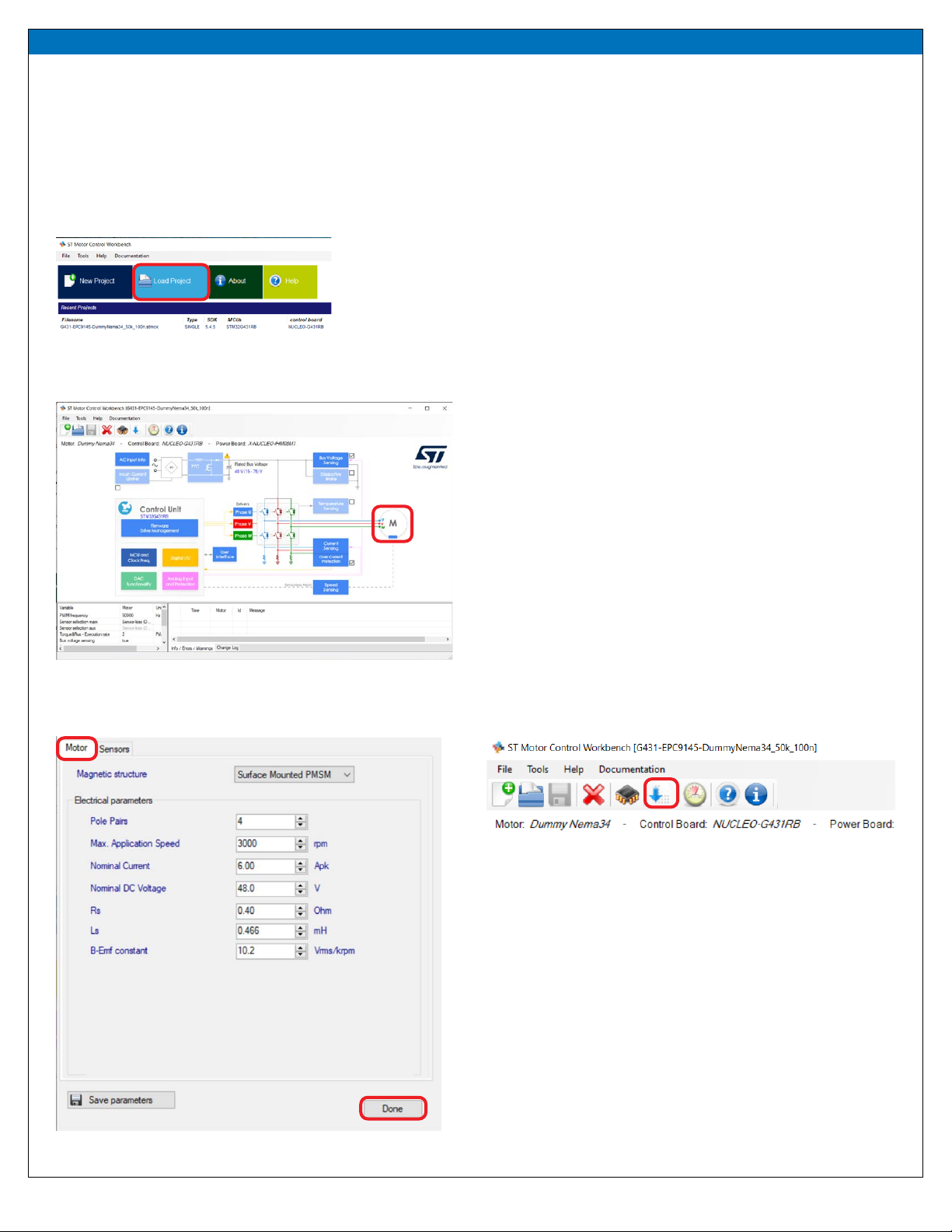
Once the software is properly installed, the user must follow this procedure:
1. Use the Motor Control Workbench with specic EPC project relevant to
the specic EPC power board being used
2. Modify the motor parameters to adapt the system to the desired motor
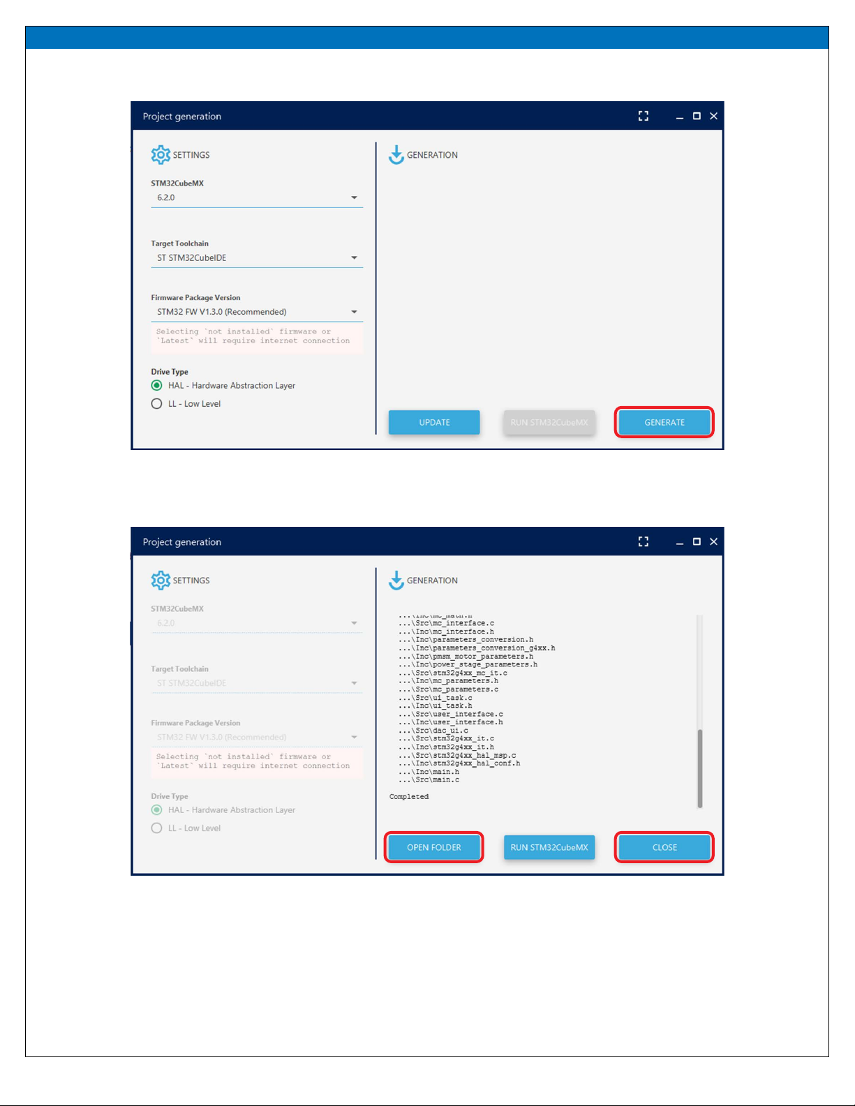
3. Generate the code
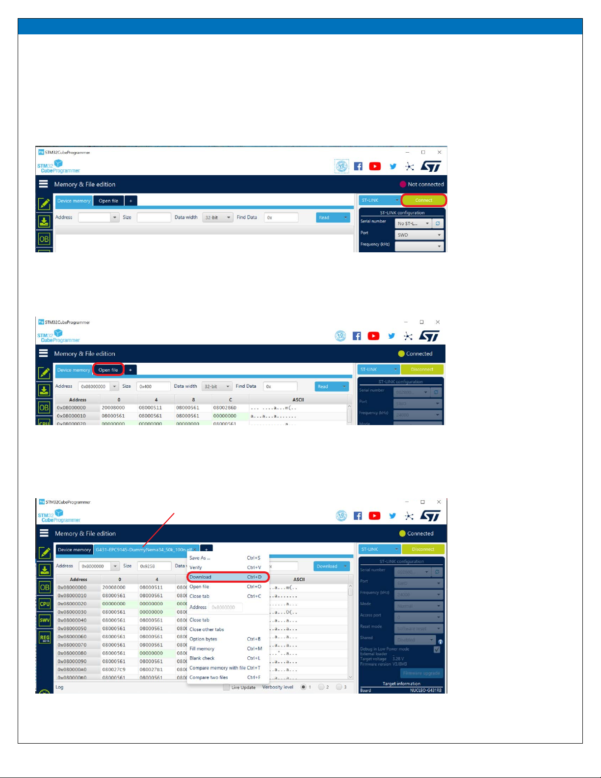
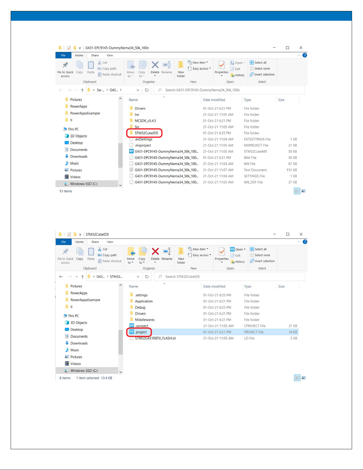
4. Use STM32CubeIDE to compile, link, and ash the generated .elf le to
the ST Nucleo board