Apollo 3300 IB 1978 User manual


Hello!
This is the owner’s manual from an 1978 Apollo 3300 IB Motorhome. It looks like a generic version
for all of Apollo’s line as the following units are included:
2600DB (Double Bed)
2600RB (Rear Bath)
2600RL (Rear Leisure Center)
3000DB (Double Bed)
3000RB (Rear Bath)
3000RL (Rear Leisure Center)
3000RBV (Rear Bath with Vanity)
3300RB (Rear Bath)
3300RBV (Rear Bath with Vanity)
3300IB (Rear Double Bed)
If you’re not sure the model you have, floor plans are included on the original page 31, 33 and 35.
The original manual was obviously dropped at one point, and the pages were rearranged to put all the
3300 IB stuff together in one spot. I rearranged it into original numerical order, but there are a couple
of pages missing as far as the numbers are concerned. It does not look like any of the original
information is missing though.
In addition, there were five additional pages that were photocopies. Annoyingly, they share page
numbers with existing pages, but the images are completely different. I added them to the end of this
PDF for sake of completeness.
Thank you!
Rick Hamell
http://Hamell.net
http://RickHamell.com

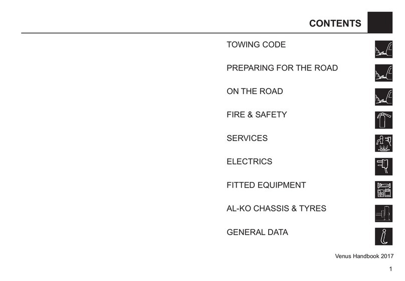
TABLE OF CONTENTS
SECTION 1—INSTRUMENTS AND CONTROLS
Driver’s Compartment . . . ..... . . . ...... . . .
Instruments and Controls ................ .
Steering Column . . .... . . . . . ......... . . . . .
Apollo Central Control .... . . . ...... . . . ...
Gas Monitor . . ... . . ...... . . . . ........ . . .
SECTION 2—OPERATING AIDS
¢I--n
-0O-O
..0~¢
--¢- -
-O-| |
Pre-Operating Checks . , ....................... .
Standard Trunk Equipment . . ...... . . . .........
Emergency Equipment .........................
Useful Equipment ........................... . .
Daily Trip Log . . . .......................... . .
SECTION 3-IDENTIFICATION
.¢- - ¢-¢-O
..» ¢ ¢--¢.
.-.QQ-¢-.
»--¢.QQ¢-
.-- - .---¢
>—~>—->—-
O'\-§I\)\IUJ
. . ....... 19
...... . .. 19
...... . .. 20
...... . .. 20
......... 21
Re-Registering Your Apollo . . . .. . ... . . . . . . . .. . . . . ....... 23
Identification ............ . .. . ............ . . . . .
I.D. Plates . . . ............. . .... , .............
Exterior 2600 Model .. . .. . ........... . ..... . ..
Floor Plans 2600 Model .. . . ...... . .. . . . ...... .
Exterior 3000 Model ....... . ......... . .... . ... .
Floor Plans 3000 Model i. . .. . . . ..... . ........ .
Exterior 3300 Model ... . . ,........ . . . .. . .. . . . . .
Floor Plans 3300 Model .... . .. . .........,.... .
SECTION 4-AUTOMOTIVE EQUIPMENT
¢u¢Qn ¢ ¢no
Qo-¢Qa~on
......... 25
......... 29
... . ..... 30
.... . .... 31
.. . . . . . .. 32
. , .... . .. 33
34
35
Fuel Tanks ...... . .... . ........................... . ....37
How to Weigh Your Apollo ......r.. . ..........
Front End Service Area ... . .. . .... . ... . r.... . . .
Fuse Block ... . C.. . . . .. . ....... . ,.............
Engine Compartment . . . ....... . . .......... . . . .
SECTION 5—EQUIPMENT OPERATION
Automotive Air Conditioner .... . ... . . ..........
Roof Air Conditioner . . . . . . ... . .. . .............
Electrical System ..‘ ... . . . .. . ...... . . . . . ........
Water and Drain System ... . .._... . . , ... . . .... . .
L.P. Gas System and Components ... . . . .........
Microwave Oven . . ......... . . ..... . .... . ......
Ice Maker . . . .. . .. . ........... . . . . . ...........
Blender . . . . ... . .......... . . . . .... . ......... . .
Vacuum Cleaner ....... . . . ....... . ...... . .... .
Automatic Entry Step . . ... . . .. . . . . .... . . . . . . . .
Horns ..................... . . ........ . . . . . . . .
uu-4 n A-nu
B¢uQQQQno
.... . . . .. 72
......... 72
.... . .... 37
......... 38
. . . . . . .wt 38
........0 40
.... . .... 41
......... 44
. . ....... 47
.....L.... 51
. . . . ..... 58
......... 67
...... . .. 69
70
7l
0716’

[W0
SECTION 6—MAINTENANCE
Sanitation and Maintenance of Water Systems
Cleaning Holding Tanks ...................
Battery Care ............. . ........... . ....
Battery Charges ................... . . . .... .
Tire Maintenance .. . .............. . . . .... .
Safety Procedures . . ...................... .
SECTION 7—STORING AND WINTERIZING
Winter Travel . . . . . . ................. . . . .. .
Storing Your Apollo ... . Q......... . . . ......
SECTION 8—DIAGRAMS
Diagram Index ... . ..... . . . ...... . ...... . .
Diagrams . . ........................... . . .
COMPONENT INDEX .................. . .... . ..

$___:___Z__H_w2_Zm__>__::WZ_
_ZO___bm%

DRIVERS COMPARTMENT
You will find that your new motor home drives and handles with comparitive
ease. For good safety, the basic thing to remember is that it is larger and heavier
than your passenger car. Because of this, allow more space for turning and do
not follow the car ahead too closely, you require more stopping space.
Sitting over the front wheel may cause you to crowd the center of the road. A
quick glance in the rear view mirrors will indicate how close your vehicle is to
the center line. GENERALLY, JUST EXERCISE MORE CAUTION IN
EVERY RESPECT. “
Before you start, however, familiarize yourself with the drivers compartment
and locate all instruments on your dashboard. We also suggest that you utilize
the check lists provided in Section 2, before starting.
Figure IDriver's Compartment
three

four
DRIVER AND PASSENGER SEATS —The driver and passenger seats
have numerous adjustments to provide you with maximum comfort. Both
seats have backward/forward adjustments, raise and lower, swivel and have
adjustable arm rests. For additional comfort the seats also recline.
To make aforward/backward adjustment, find the two levers located under
the forward center position of the seat. Move the smaller, top iever to the left
and slide the seat to the desired position. To swivel the seat, depress the larger,
lower lever and turn. Simply lift or lower the arrnrests as desired. To recline or
raise the seat back, locate the knob at thejunction of the seat and back. Then
simply dial the desired position. To make avertical adjustment, depress the
swivel release, hold in the down position and slowly pull straight up on the
seat. After the seat has traveled W’, release swivel. Continue lifting the seat
approximately another 3/4” until swivel lock engages the next higher position.
To continue the adjustment, repeat the operation. After satisfactory height
has been found, loosen fasteners on clamp ring, check for swivel and re-
engagement of swivel lock.
Both seats are equipped with seat belts. To lengthen belt to fit, turn the buckle
perpendicular to the belt, and pull to desired length. To shorten, pull loose end
of belt.
CA UTION: Move seat forward before swiveling.

Figure 2Parking Brake
PARKING BRAKE
On the oor to the left ofthe drivers seat is the parking brake. To engage, push
the lever forward. To release, pull the lever back to the “UP” position.
At the top ofthe lever is aknob that adjusts the tension ofthe SET/RELEASE
lever. To INCREASE tension, turn the knob clockwise; to DECREASE the
tension, turn the knob counterclockwise.
OVERHEAD BUNK
The 2600 Series coach may be equipped with an overhead bunk. In order to
use the bunk, first move the front seats as far forward as possible. Then, turn
each seat so they face each other. and push them against their respective walls.
Now the overhead bunk may be pulled down into the sleeping position.
V6

SIX
BATTERY SELECTOR SWITCH
The battery selector switch is located below the left hand side of the driver’s
seat. It has four positions; OFF, 1,2, or BOTH. For normal driving, set the
switch to “BOTH” to insure that each battery receives acharge. While camp-
ing, set the switch to position 1(the larger battery) and leave battery 2in reserve
to insure that both batteries are not inadvertently discharged. When starting
engine or auxiliary generator, place selector switch to “BOTH” to utilize full
starting power. After starting, selector should remain on “BOTH” position.
In the event that both batteries are weak, put the switch to “BOTH” to start
your engine.
If coach is being used and no charging sources are running, turn battery selec-
tor switch to #1. This leaves the other battery fully charged for starting the
engine.
From time to time while camping, check the batteries by observing the meter
on the central control panel. When the coach is not in use, be sure the selector
is ALWAYS set to “OFF.”
When your power plant (generator) is running, or when hooked to shore power,
both batteries are charged if battery selector switch is set to “BOTH.”
Figure 3Battery Selector Switch
CA UTION: Ifswitch is turned to “OFF” when generator is running or when
hooked to shore power, converter damage will result.

INSTRUMENTS AND CONTROLS
It is important that you familiarize yourself with the various instruments and
controls and utilize the check lists, BEFORE YOU OPERATE YOUR
MOTOR HOME!
r»l~.»ww-
it
wm
Figure 4Dash Instruments &Controls
l. FUEL GAUGE —With ignition key in ON or ACCESSORY position,
the pointer will indicate the amount of fuel in the gas tank. The selector
switch permits the contents of each tank to be checked conveniently.
2. AMMETER —Indicates whether battery is being charged or dis-
charged. Pointer will normally remain slightly to the right of center while
driving when battery is fully charged. If the indicator is continuously to
the left, indicating discharge, the electrical system should be examined
immediately.
3. VACUUM GAUGE (MOTOR MINDER) --Indicates engine mani-
fold vacuum. Try to maintain the highest reading possible when driving.
This will result in the best fuel economy and maximum engine life.
4. TEMPERATURE GAUGE —- Indicates engine coolant temperature.
Pointer will normally stay near center but may rise slightly in congested
traffic or under heavy load. DO NOT OPERATE VEHICLE IF INDI-
CATOR REMAINS IN HIGH TEMPERATURE RANGE AT
RIGHT EXTREMITY OF GAUGE.
S€'\/8!”!

eight
5. OIL PRESSURE GAUGE -— The oil pressure gauge indicates oil pres-
sure only. Pointer should always show some pressure when the engine is
operating. EF NO PRESSURE IS ENHICATEEYA STOP ENGINE
In/TMEDIATELEI ?3O FQOT OPERAETE UNTEL "THE BIFFL
CULTY ES €ORER.E;€"TED.
6. TURN SIGNAL lNEilCA?f€)§RS ---The lights T2-Ylash in unison with the
outside lamps when the turn signal is activated.
7. HIGH BEAM INDICATOR -— Blue light indicates that headlights are
on high beam.
8. ODOMETER &SPEEDOMETER --- Odometer indicates total mileage
accumulated. Speedometer indicates speed of vehicle in miles per hour.
Also included is atrip meter, adjustable for distances under 1,000 miles.
9. BRAKE SYSTEM WARNING LIGHT -The dual brake system pro-
vides areserve braking capability in the event of failure of the hydraulic
system. Failure of either half of the dual system is indicated by the brake
warning light which will glow when the brake pedal is depressed.
WARNING: IF BRAKE FAILURE IS INDICA TED, IMMEDIA TE
REPAIR SER VICEIS NECESSAR Y. CONTINUED OPER-
ATION OF VEHICLE IN THIS CONDITION IS DANGER-
OUS. 7he warning light is connected to the ignition switch and
an automatic‘ checkfor its malfunction is performed by starting
the engine. The light will go on when the key is turned to the
START position and will go off as soon as the engine starts.
10. TRANSMISSION FLUID LEVEL SENSOR -— This sensing unit is an
integral part of the transmission oil dip stick. Athermistor is used to
detect changes in oil level once the level has decreased to the add mark on
the dip stick with the engine in neutral and the transmission oil at amini-
mum temperature of 130° F. If oil is not detected when both of these
conditions are met, the resistance across the thermistor will change,
resulting in current flow and hence, the lighting of awarning light indi-
cating 8low oil condition.
ll. TRANSMISSION OIL TEMPERATURE —Transmission oil tem-
perature is monitored by adevice with readout on atemperature gauge.
Only the discharge oil temperature will be monitored at the converter out
point, since this is the highest oil temperature in the system. Oil temper-
ature measurement range is from 150° F. to 300° F. Any temperature in

excess of 285° F. will show in the red warning zone of the temperature
gauge.
Figure 5Temp/ lzvel Sensor lndirarors
12. ENGINE OIL LEVEL SENSOR WThis unit is an integral part of the
engine oil dip stick using athermistor as the level sensor. The oil level
must be checked with the engine off; after a“wait” ofapproximately l5
seconds. (this is to allow oil trapped in the gallies and rocker covers to
return to the oil pan) Depress the red button and observe the lamp. lfthe
lamp is actuated. this will indicate alow oil condition.
13. ENGINE COOLANT LEVEL SENSOR This sensor is installed in
the radiator, thus becoming an integral part ofthe vehicle cooling system.
If the coolant level in the radiator drops below the pre-determined level,
the section labeled Coolant Level will illuminate red.
l4. WINDSHIELD WASHER ~Push the windshield washer switch to
spray fluid on the windshield. Fluid will be dispensed only while switch
is depressed.
IN COLD WEATHER TWO PRECAUTIONS SHOULD BE TAKEN:
a. The windshield washer fluid should be mixed with aspecial anti-freeze
manufactured for this use.
b. After the engine has warmed, operate the defroster for afew minutes
to reduce the possibility of smearing or freezing the fluid on the cold
windshield.
I'1lH€

Figure 6Dash Detail
15. WINDSHIELD WIPER —- Your Apollo has two independent wind-
shield wiper motors, one for each half of the windshield. The switches are
identified “LEFT WIPER” and “RIGHT WIPER”. Depress the upper
portion of the switch for normal operation, or the lower portion of switch
for high speed. In cold weather always turn offthe wiper motor and allow
the wipers to return to original position before turning off the engine. Be
certain wipers are not frozen to windshield prior to activating wiper
control.
16. HEADLIGHTS —Pull the headlight control to the first position for
parking lights and to the second for headlights. Rotation of switch regu-
late brightness of instrument panel lighting.
NOTE: Periodically check for burned out bulbs or damaged lenses.
17. HEADLIGHT DIMMER SWITCH —Depress the button on the oor
to the left of the steering column to change the beam from high to low.
18. I.C.C. LIGHT/COURTESY BLINKER —— By depressing this switch,
I.C.C. lights, which are located on the roof crown, will ash off. This can
be used as amatter of courtesy when passing another vehicle.
NOTE: Lights will remain OFF only while switch is being depressed.

AUTOMATIC FUEL TANK SELECTOR -— Your Apollo is equipped
with two fuel tanks, amain and an auxiliary. When fuel switch is
depressed on the MAIN side, you will be drawing fuel from the main tank
and fuel gauge will register the contents of this tank. Depress the
AUXILIARY side of the switch and you will be drawing fuel from the
auxiliary tank. The fuel gauge will then register the contents of this tank.
The generator draws its fuel from the AUXILIARY tank at all times and
is unaffected by operator selection. i
EMERGENCY FLASHER —The asher switch is located below the
steering wheel on the right side of the steering column. This switch should
be activated whenever the vehicle is stopped on or alongside the
roadway.
ASHTRAYS AND LIGHTER -Depress lighter and release. When
lighter pops out, coils will be red hot for light.
GENERATOR “START &STOP SWITCH“ —This switch is clearly
marked and operates the generator. Depress the switch to START and
hold until generator starts. To stop generator, depress switch to STOP
for approximately ten seconds. An indicator light in the switch is lit when
generator is running. Additional information regarding the generator is
in the Electrical System of Section 15, Equipment Operation.
HEADPHONE JACKS -STEREO &CB —Headphones may be used
for either stereo or CB Radio. When the headphones are plugged in, the
normal speakers are cancelled out.
CAUTION: In some states it is illegalfor the driver 10 wear headphones
while operating the vehicle. Please check appropriate state
traffic laws.
AISLE LAMP Your Apollo is equipped with aseries of lamps located
near the oor line. These lamps provide mood lighting and low level
illumination for night driving.
OVERHEAD BLOWER —The overhead blower switch is located on
your dash. The overhead blower will recirculate interior air. To remove
smoky or stale air, vent one window while operating the overhead blow-
ers. To aid in the defrosting of the windshield, turn the blowers toward
the windshield. They will draw the warm air produced by the defroster
and blow it back onto the windshield.
eleven

twelve
Figure 7Steering Column
ADJUSTABLE STEERING COLUMN
For your driving comfort, the steering column is adjustable. Near the floor to
left of the steering column, is apedal. Depress this pedal and move the steering
wheel to the desired position. When the pedal is released, the steering column
will be locked into position.
IGNITION SWITCH
The ignition switch is on the righthand side of the steering column just below
the steering wheel. The switch has four positions: ACCESSORY, OFF, RUN
and START. When the key is turned to ACCESSORY, the electrical equip-
ment powered through the switch can be operated.
To activate the ignition system, turn the key clockwise to RUN. To start the
engine, turn the key clockwise as far as it will go. When the engine starts, release
the key and it will return to the RUN position.
To remove the key, turn to the “OFF” position marked on the steering column.

TURN SIGNALS
Use the turn signals whenever aright or left turn is made, when changing
lanes, or when pulling away from the curb. Signal your intention at least ten
seconds before making the maneuver.
CAUTION: D0 not rnake abrupt lane changes.
If the asher operates weakly or fails to flash, one possible cause is aburned
out bulb. Immediate bulb replacement is essential to safe motoring.
AUTO-PILOT CRUISE CONTROL
The switch can be found on the turn signal lever. Under normal conditions,
this system will only engage at speeds above 30 mph. To activate the auto-
matic speed control, drive at the desired speed, slide the switch from “OFF”
to the “ON” position and release. Press the button on the end of the signal
lever which will engage the cruise control and hold at the speed you are tra-
veling at that time. To disengage, depress the brake pedal. To resume the pre-
set speed, move the switch to “RES” and the coach will return to its former
speed.
$~\ ~~<1t.-
rs.» >-<=
Figure 8Auto Pilot Cruise Control
thirteen

fourteen
APOLLO CENTRAL CONTROL
The Apollo Central Control incorporates numerous useful instruments and
controls. The panel gives you information at your finger tips regarding the
coach fluid, gas and electrical system. Please familiarize yourself with the fea-
tures of the panel and use it frequently.
Figure 9Apollo Central Control
Your Apollo Central Control is conveniently installed in the range hood.
Below is adescription of the features found on the control panel.
l. REFRIGERATOR ALARM SWITCH —This switch should be turned
ON when operating the refrigerator on the Gas Mode. When switched ON
abuzzer will sound if the ame on the refrigerator should go out. When
operating on the Electric Mode this switch should be turned OFF.
2. L.P. GAS SWITCH —This switch allows aremote check of the quanity of
L.P. Gas. Simply depress the switch and observe the level indication above.
3. HOOD FAN AND LIGHT —These switches operate the hood fan and
light. The hood fan has afilter which should be cleaned periodically in
warm water and soap.
4. GENERATOR CONTROLS -The generator START/ STOP switch
remotely operates the generator. The hour meter records TOTAL HOURS
of operation for the generator. Use this information to schedule periodic
maintenance and determine fuel needs. Refer to Electrical Systems for
additional information.

HOLDING TANK LEVEL SWITCH —This switch is used to determine
the level of the waste holding tanks. Depress switch for desired tank and
observe the level indication above.
WATER LEVEL SWITCH —This switch is used to determine the Fresh
Water Level in the storage tank. Depress switch and observe the level indi-
cation above.
BATTERY CONDITION SWITCH —This switch provides acheck of
the coach batteries located under the entry step. Depress switch and observe
indication above.
WATER PUMP SWITCH —The water pump switch energizes the water
pump and makes the fresh water system ready to use.
fteen

SlXl€€n
GAS MONITOR
The Apollo Gas Monitor gas detector system is specifically designed to detect
LPG, Propane, Butane, Alcohol vapor and Gasoline vapor. Also detected are
Acetone, Benzene, Hydrogen, Hydrogen Sulfide, M.E.K., Methyl Alcohol,
Octaine and other deoxidizing gases and vapors.
Figure I0 Gas Monitor
Operating Instructions:
During intervals when the POWER is OFF to the remote detectors, the gas
sensor elements absorb atmospheric gases and water vapor. When switched
ON, the detectors go into an alarm state for up to 3minutes until these gases
and water vapor are driven from the sensors. An automatic 5minute Alarm
MUTE cycle is initiated when power is switched ON.
l. Set Power switch to ON; note that the green power LED* and the red
MUTE LED go ON. Within afew seconds each DETECTOR LED
on the monitor panel will go ON but no sound will be heard because
of the Automatic MUTE timer. Each DETECTOR LED will go out
within 3minutes. In 4to 5minutes the MUTE LED will go out. The
system is now ready to detect dangerous gases.
2. Test each remote detector by injecting asmall amount of gas from a
butane lighter into the bottom of the detector (DO NOT strike aame
on the lighter, just hold down the gas release lever briefly). Within a
few seconds the alarm should sound. This test should be repeated
periodically.
*LED: Light Emitting Diode

Each remote detector has an LED that monitors the gas sensor ele-
ment’s heater current. This LED should be ON when the POWER
switch on the Monitor Panel is ON. Ifthe LED is not ON, the remote
detector is inoperative and must be serviced or replaced.
3. Nuisance alarms can be caused by small amounts of alcohol vapor (less
than 2% of the L.E.L.). Nuisance alarms may be silenced for 10 min-
utes by pressing the MUTE pushbutton. ANUISANCEalarm must be
treated as aREAL alarm until the source has been clearly identified.
Common sources for alcohol vapors include: aftershave lotion, co-
logne, stick deodorant and heated alcoholic beverages. Small amounts
of certain other vapors will also sound the alarm. Included are: methyl
alcohol, isopropyl alcohol, acetone, M.E.K. and benzene. These sub-
stances are toxic to humans and should not be used without adequate
ventilation.
Hairspray and other aerosols will sound the alarm; however, these
vapors are highly volatile and must be treated as potentially explosive
gases, especially in confined spaces.
4. During periods of vehicle storage the Gas Monitor should be switched
OFF to avoid discharging the vehicle’s storage batteries. When the Gas
Monitor is switched OFF the vehicle’s L.P.G. tanks should be shut off
as asafety measure. The Gas Monitor should not be left on for more
than 48 hours (4 detector system) without recharing the vehicle’s stor-
age batteries. If abattery charger is connected, the system may be left
ON continuously.
5. Low battery voltage (5 to 6volts) will cause the alarm to sound, but
none of the DETECTOR LED’s on the Monitor Panel will be ON. The
battery should be recharged when this occurs.
If The Alarm Sounds:
1. DO NOT switch on lights or strike amatch.
2. Evaluate the vehicle.
3. Leave door and windows open.
4. Shut off LP Gas at the tanks.
5. Alarm automatically resets when gas is at asafe level.
seventeen
This manual suits for next models
9
Table of contents