HEADQUARTERS:AndersonPowerProducts®,13PrattsJunctionRoad,Sterling,MA01564-2305 USA
T:978-422-3600 F:978-422-3700www.andersonpower.com HEADQUARTERS:AndersonPowerProducts®,13PrattsJunctionRoad,Sterling,MA01564-2305 USA
T:978-422-3600 F:978-422-3700www.andersonpower.com
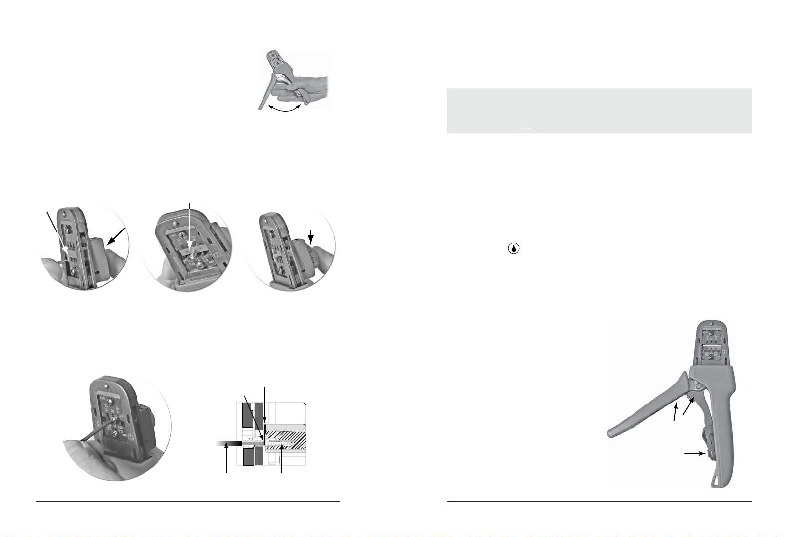
Figure 5 Figure 5a
OPERATION
Open the tool by squeezing the handles together.At the end of the
closing stroke, the ratchet mechanism will release the handles and
the hand tool will spring open. (See Figure 1)
Crimping Terminals
1. Select the desired terminal listed in the preceding charts.
2. HandlesofthetoolsmustbeinthefullyopenpositionasinFigure
1. With the locator attached, push the locator button on the back
of the hand tool to bring the locator forward through the tooling.
(See Figure 2)
3. While holding the locator button in, load the terminal into the
proper nest opening in the locator based on the wire gauge or
terminal type markings on the hand tooling. (See Figure 3)
7. Crimptheterminalbysqueezingthetoolhandlesuntiltheratchetmechanismcyclehasbeencompleted.
Release the handles to open the jaws.
8. Remove the crimped terminal from the terminal locator by pulling on the wire.
9. Visually inspect the crimped terminal for proper crimp location.
RatchetingHandleSqueeze
handlestogetherandrelease
handlewillspringopen
Figure 1
4. Release the locator button, allowing the locator to return to the crimping position. (See Figure 4)
5. Close the tool handle until the first ratchet position engages.
6. Insert the properly stripped wire through the terminal and against the wire stop. (See Figure 5 & 5a)
Figure 2 Figure 3 Figure 4
Maintenance
It is recommended that each operator of the tool be made aware of, and responsible for, the following
maintenance steps:
1. Remove dust, moisture, and other contaminants with a clean brush, or soft, lint free cloth.
2. Do not use any abrasive materials that could damage the tool.
3. Make certain all pins; pivot points and bearing surfaces are protected with a thin coat of high
quality machine oil (See Figure 6).Do notoil excessively. Lightoil(suchas30weightautomotive
oil) used at the oil points, every 5,000 crimps or 3 months, will significantly enhance the tool life.
4. Wipeexcess oilfrom handtool, particularly from crimping area.Oil transferredfrom thecrimping area
onto certain terminations may affect the electrical characteristics of an application.
5. When tool is not in use, keep the handles closed to prevent objects from becoming lodged in the
crimping dies, and store the tool in a clean, dry area.
Wirestop is part
ofthelocator
Wireagainstthe
wirestop
Wire Terminal
Note: Acrimp height chart is provided with this manual as Reference Only. Due to the wide range of
wires, strands, insulation diameters, and durometers available, actual crimp height measurements
may vary slightly.An occasional, destructive, pull force test should be performed to check hand tool
crimp. Pull Force value Must exceed the minimum pull force specifications listed.
LubricationPoints
(usea light oil every 3
monthsor5,000crimps)
Figure 6
Releaselocator
buttonwithcontact
inserted
Terminalloadedintolocator
LocatorPushed
thrutool Locatorbutton
pushedin


