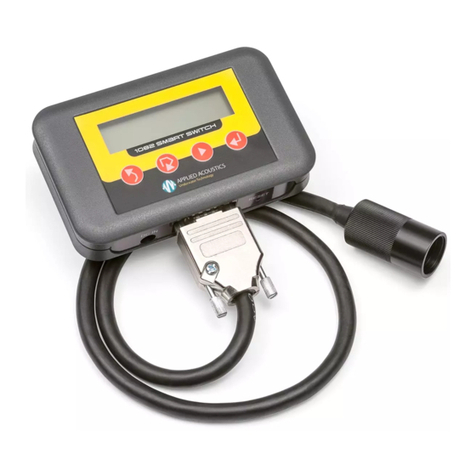
APPLIED ACOUSTICS 1082 User manual

1082 Smart Switch
Firmware Version 1.12
Operation Manual

1082 Smart Switch Operation Manual
CHA-1082-8000/11
__________________________________________________________________________________________________________
__________________________________________________________________________________________________________
Page 2of 48
THIS PAGE IS INTENTIONALLY LEFT BLANK

1082 Smart Switch Operation Manual
CHA-1082-8000/11
__________________________________________________________________________________________________________
__________________________________________________________________________________________________________
Page 3of 48
Revision History
Issue Change
No. Reason for change Date
11 1852
Additions for 1100 Series Beacons and Sigma2, refer to DCR
note. 15/08/17
10 1501
Addition to Section 3.4.1 Identified Beacon Model and
Configuration Message, refer to DCR note. 22/07/14
9 1480
Addition to Section 3.5.1 Channel, refer to DCR note.
Other minor amendments. 13/06/14
8 1335 Minor amendments to Sections. 29/05/13
7 1330
Addition to Section 3.8.3 Fast Charge Termination, refer to DCR
note.
Other minor amendments. 02/05/13

1082 Smart Switch Operation Manual
CHA-1082-8000/11
__________________________________________________________________________________________________________
__________________________________________________________________________________________________________
Page 4of 48
Table of Contents
REVISION HISTORY......................................................................................................................................... 3
1. INTRODUCTION TO THE 1082 SMART SWITCH...................................................................................... 6
2. GETTING STARTED..................................................................................................................................... 7
2.1 USER INTERFACE ....................................................................................................................................... 7
2.2 CONNECTOR PANEL.................................................................................................................................... 8
2.3 INTERNAL BATTERY .................................................................................................................................... 8
3. SMART SWITCH OPERATION.................................................................................................................... 9
3.1 CONNECTING TO A BEACON ........................................................................................................................ 9
3.2 SERIAL COMMUNICATION ............................................................................................................................ 9
3.3 MAIN MENU OPTIONS ............................................................................................................................... 10
3.4 FAST ID BEACON...................................................................................................................................... 11
3.4.1 IDENTIFIED BEACON MODEL AND CONFIGURATION MESSAGE................................................................... 12
3.5 BEACON CONFIGURATION ......................................................................................................................... 14
3.5.1 CHANNEL.............................................................................................................................................. 16
3.5.1.1 AAE CHANNEL................................................................................................................................... 17
3.5.1.2 SIGMA2QUICKSET ............................................................................................................................. 18
3.5.1.3 SIGMA2CHANNEL .............................................................................................................................. 19
3.5.1.4 IXB CHANNEL .................................................................................................................................... 21
3.5.1.5 SWB QUICKSET................................................................................................................................. 23
3.5.1.6 SWB CHANNEL.................................................................................................................................. 24
3.5.2 BATTERY............................................................................................................................................... 25
3.5.3 DEPTH STATUS ..................................................................................................................................... 26
3.5.4 SERIAL NUMBER.................................................................................................................................... 26
3.5.5 MCU FIRMWARE VERSION..................................................................................................................... 27
3.5.6 DSP FIRMWARE VERSION...................................................................................................................... 27
3.6 RESPONDER TEST.................................................................................................................................... 28
3.7 TRICKLE CHARGE..................................................................................................................................... 29
3.8 FAST CHARGE.......................................................................................................................................... 30
3.8.1 FAST CHARGE ACTIVATION .................................................................................................................... 31
3.8.2 FAST CHARGE STATUS .......................................................................................................................... 32
3.8.3 FAST CHARGE TERMINATION.................................................................................................................. 33
3.9 SMART SWITCH CONFIGURATION............................................................................................................... 36
3.9.1 FIRMWARE VERSION.............................................................................................................................. 36
3.9.2 BACKLIGHT............................................................................................................................................ 37
4. FIRMWARE UPGRADE.............................................................................................................................. 37
5. BATTERY REPLACEMENT ....................................................................................................................... 37
6. PRODUCT RECYCLING / DISPOSAL....................................................................................................... 37
7. SPARES..................................................................................................................................................... 38
8. FAULT FINDING........................................................................................................................................ 38
9. SPECIFICATION........................................................................................................................................ 39
10. TRANSPORTATION BY AIR.................................................................................................................... 41
11. APPENDIX A CONNECTOR DETAILS.................................................................................................... 42
12. APPENDIX B QUICK START GUIDE....................................................................................................... 44
13. APPENDIX C FIRMWARE UPDATE INSTRUCTIONS............................................................................ 45

1082 Smart Switch Operation Manual
CHA-1082-8000/11
__________________________________________________________________________________________________________
__________________________________________________________________________________________________________
Page 5of 48
Thank you for choosing Applied Acoustic Engineering as one of your subsea equipment suppliers.
We hope you experience many years of reliable operational use from our products.
If you do encounter any technical issues with any of our products then please don’t hesitate to
contact our Technical Team via the following methods.
Tel: +44 (0)1493 440355
Fax: +44 (0)1493 440720
Applied Acoustic Engineering Ltd has made every effort to ensure that the information contained in this
manual is correct at time of print. However our policy of continual product improvement means that we
cannot assume liability for any errors which may occur.
These written instructions must be followed fully for reliable and safe operation of the equipment that
this manual refers to. Applied Acoustic Engineering Ltd cannot be held responsible for any issues
arising from the improper use or maintenance of equipment referred to in this manual or failure of the
operator to adhere to the instructions laid out in this manual. The user must be familiar with the
contents of this manual before use or operation.

1082 Smart Switch Operation Manual
CHA-1082-8000/11
__________________________________________________________________________________________________________
__________________________________________________________________________________________________________
Page 6of 48
1. Introduction to the 1082 Smart Switch
The AAE 1082 Smart Switch is a pocket size solution to configuration, testing and charging of AAE
1000 / 1100 Series beacon ranges.
Main features are: -
AAE 1000 / 1100 Series beacon configuration, including channel and depth telemetry
transmission selection.
AAE 1000 / 1100 Series beacon fast charge activation and monitoring.
Compatible AAE beacon trickle charging.
Compatible AAE beacon responder mode testing.
Internal rechargeable battery.
Firmware field upgradeable.
The 1082 Smart Switch has limited compatibility with other AAE beacon ranges. Refer Section 3
Smart Switch Operation for details.
On delivery, check the following is included: -
1082 Smart Switch.
30VDC power supply unit (100-250VAC mains input).
Mains lead (IEC).
Beacon Connection Cable (9-way ‘D’ plug to MCIL5F 5-way socket).
RS232 serial cable (9-way ‘D’ plug to 9-way ‘D’ socket).
Please check contents for transit damage. If any is found, do not use the equipment and return it to
your supplier.

1082 Smart Switch Operation Manual
CHA-1082-8000/11
__________________________________________________________________________________________________________
__________________________________________________________________________________________________________
Page 7of 48
Standing by
Fast ID Beacon
2. Getting Started
2.1 User Interface
The Smart Switch user interface comprises a 2-way backlit L.C.D. and four stylised selection keys
on the face of the unit. The Smart Switch does not include a power switch the unit is ‘always on’.
After two minutes of no user activity, i.e. no key presses, the Smart Switch will revert to very low
power standby with a blank display. In standby, pressing any selection key will ‘wake’ the Smart
Switch to its state prior to standby. The L.C.D. backlight is enabled for a brief period when any
selection key is pressed. The backlight can be disabled if required. Refer Section 3.9 Smart Switch
Configuration for details.
Fig. 1
The L.C.D. top line displays information or instructions for the user together with icons indicating
Smart Switch operating status: -
The L.C.D. bottom line displays the current menu item for selection or selected menu item
instructions. Icons representing the four selection buttons are displayed to the left and to the right
of the menu item. Icons to the left represent navigation options. Icons to the right represent
selection options (if available).
NEXT
UP SHIFT SELECT
Smart Switch internal battery charge
Serial communication inactive
Attempting serial communication with beacon
Serial communication active with beacon
Trickle charge or fast charge active
MENU ITEM /
INSTRUCTION
NAVIGATION
OPTIONS
INFORMATION /
INSTRUCTION ICONS
SELECTION
OPTIONS

1082 Smart Switch Operation Manual
CHA-1082-8000/11
__________________________________________________________________________________________________________
__________________________________________________________________________________________________________
Page 8of 48
Standing by
Fast ID Beacon
LOW BATTERY!
PLUG IN DC PSU
DC IN RESET
2.2 Connector Panel
A connector panel includes a DC input socket for the included 30VDC power supply unit, a 9-way
‘D’ socket for RS232 serial communication and beacon charging, and a reset button concealed
against accidental operation. Refer Section 10 Appendix for details.
Fig. 2
2.3 Internal Battery
The Smart Switch is powered from an internal rechargeable NiMH battery pack. With the Smart
Switch ‘awake’ and operational, the L.C.D. displays a battery icon at all times, representing the
current internal battery charge.
Fig. 3
Operational life is typically 2 days with constant use and with the backlight enabled. Standby life is
typically 5 months.
The Smart Switch internal battery is trickle charged at 40mA when the included 30VDC power
supply unit is inserted. When inserted, the Smart Switch is powered directly from the power supply
unit.
When the internal battery is near exhausted, the Smart Switch will constantly display a low battery
warning, as Fig. 4.
Fig. 4
The Smart Switch will be non-operable until the internal battery has been partially charged. Insert
the included 30VDC power supply unit. After a period of trickle charging, the Smart Switch will
reset and become operable.
DC INPUT
SOCKET 9-WAY ‘D’
SOCKET RESET
BUTTON
BATTERY FULL CHARGE
BATTERY LOW CHARGE
9-WAY ‘D’
SOCKET

1082 Smart Switch Operation Manual
CHA-1082-8000/11
__________________________________________________________________________________________________________
__________________________________________________________________________________________________________
Page 9of 48
3. Smart Switch Operation
3.1 Connecting to a Beacon
Your Smart Switch arrives supplied with a Beacon Connection Cable for connection to compatible
AAE beacons. Connect the cable between the Smart Switch connector panel 9-way ‘D’ socket and
compatible AAE beacon 5-way MCBH5M bulkhead plug.
When trickle charging or fast charging a connected beacon, it is recommended the Beacon
Connection Cable be locked securely to the beacon and to the Smart Switch. Refer Section 3.7
Trickle Charge and Section 3.8 Fast Charge.
3.2 Serial Communication
The Smart Switch and a connected 1000 / 1100 Series beacon support RS232 serial
communication at 9600 baud only. Refer Section 8 Specification for serial communication
specification.
NOTE: - Serial communication is only possible when a connected beacon is switched ON
NOTE: - Serial communication is not possible when a connected beacon is fast charging. Serial
communication is possible when a connected beacon is trickle charging.
The Smart Switch and a connected beacon communicate in an AAE defined command format,
including error checking of serial messages.
The Smart Switch will display a “Selected!” or “Refreshed!” message if a serial message from a
connected beacon indicates it processed a user selection correctly.
The Smart Switch will display a “Failed!” message if a serial message from a connected beacon
indicates it did not successfully process a user selection.
The Smart Switch will display a “Comms error!” message if a serial message from a connected
beacon fails error checking.

1082 Smart Switch Operation Manual
CHA-1082-8000/11
__________________________________________________________________________________________________________
__________________________________________________________________________________________________________
Page 10 of 48
Standing by
Fast ID Beacon
Standing by
Responder Test
Standing by
Beacon Config
Standing by
Trickle Charge
Standing by
Fast Charge
Standing by
Smart Switch
3.3 Main Menu Options
The Smart Switch menu structure has a top tier of 6 main menu options. Press for next main
menu option. Press to select a main menu option: -
Fig. 5
Change or inspect a connected 1000 / 1100 Series
beacon configuration. Includes beacon channel, beacon
depth telemetry status, beacon battery voltage, etc.
Test responder function of a connected compatible AAE
beacon.
Trickle charge a connected compatible AAE beacon.
Requires included 30VDC power supply unit.
3.4
3.5
3.6
3.7
3.8
3.9
Fast charge a connected 1000 / 1100 Series beacon.
Requires included 30VDC power supply unit.
Smart Switch configuration.
Quickly identify a connected 1000 / 1100 Series beacon
model and channel.

1082 Smart Switch Operation Manual
CHA-1082-8000/11
__________________________________________________________________________________________________________
__________________________________________________________________________________________________________
Page 11 of 48
Standing by
Fast ID Beacon
Searching. . .
Fast ID Beacon
MDL=1019D
Fast ID Beacon
3.4 Fast ID Beacon
Quickly identifies a connected beacon model and configuration.
NOTE: - This action is not required prior to configuring a connected beacon. Refer Section 3.5 for
further information.
Press to initiate. The Smart Switch will attempt serial communication with a connected beacon,
indicated by a “Searching...” message to the user.
If a connected beacon is ‘found’, the identified beacon model and channel configuration will be
displayed as a scrolling message to the user. Once communication has been established with a
connected beacon, the Smart Switch will maintain communication with the beacon. If no beacon is
found after a fixed number of attempts, the Smart Switch will stop communication and revert to
“Standing by”.
Fig. 6
NOTE: - Fig.6 beacon model for example only.
Serial communication inactive.
Attempting serial communication
with beacon.
Serial communication active
with beacon.

1082 Smart Switch Operation Manual
CHA-1082-8000/11
__________________________________________________________________________________________________________
__________________________________________________________________________________________________________
Page 12 of 48
3.4.1 Identified Beacon Model and Configuration Message
An identified beacon model and configuration is displayed as a scrolling message to the user. This
message is composed from the following: -
Beacon Model
“MDL=1019D” Beacon model, 1019D in this example.
Enabled Options (only displayed for beacons with MCU firmware revision 4.00 onward)
“OPT=1,3” Options 1 and 3 are enabled in this example. Contact Applied Acoustics for
details.
Configuration
“CFG=AAE” AAE defined “channel” configuration (including Sigma1™).
“CFG=SIGMA2” AAE Sigma2™ configuration.
“CFG=IXB” iXBlue (IXB) compatible configuration.
“CFG=SWB” Sonardyne Wideband™ (SWB) compatible configuration.
Depending on configuration, the message is completed from the following: -
AAE Defined “Channel” Configuration
“CH=01” AAE “channel”, 01 in this example.
AAE Sigma2 Configuration
“QS=1” Sigma2 “Quickset” configuration, 1 in this example.
“WUT=0” Wake-Up Tone (WUT), 0 in this example.
“IC=00” Interrogate Code (IC), 00 in this example.
“RC=00” Reply Code (RC), 00 in this example.
“TATX=0100ms” Turn-Around-Time Extension (TATX), 100ms in this example.

1082 Smart Switch Operation Manual
CHA-1082-8000/11
__________________________________________________________________________________________________________
__________________________________________________________________________________________________________
Page 13 of 48
iXBlue (IXB) Compatible Configuration
“IF=19.5kHz” Interrogate Frequency (IF), 19.5kHz in this example.
“RC=00” Reply Code, 00 in this example.
“TAT=020ms” Turn-Around-Time (TAT), 20ms in this example.
Sonardyne Wideband™ (SWB) Compatible Configuration
“QS=A1” “Quickset” if configuration matches, A1 in this example.
“IC=CIF” Interrogate Channel (IC), CIF in this example.
“ACA=0101” Acoustic Command Address (ACA), 0101 in this example.
“TAT=062.5ms” Turn-Around-Time (TAT), 62.5ms in this example.
Example
“MDL=1019D CFG=AAE CH=01”
NOTE: - Refer AAE beacon manual for AAE “channel” listings.
Sonardyne Wideband™ is a registered trademark of Sonardyne International Ltd
ADP Number 0880985001

1082 Smart Switch Operation Manual
CHA-1082-8000/11
__________________________________________________________________________________________________________
__________________________________________________________________________________________________________
Page 14 of 48
3.5 Beacon Configuration
Contains further sub menu options for beacon configuration: -
Fig. 7
3.5.3
3.5.2
3.5.1
3.5.4
3.5.5
Select beacon channel configuration.
Check or select beacon depth
telemetry transmission status.
Check beacon battery voltage.
Check beacon serial number.
Check beacon MCU firmware
version.
Check beacon DSP firmware
version.
3.5.6

1082 Smart Switch Operation Manual
CHA-1082-8000/11
__________________________________________________________________________________________________________
__________________________________________________________________________________________________________
Page 15 of 48
Press to return to top tier menu option “Beacon Config”. Press for next sub menu option.
Press to select a sub menu option.
On selection of a sub menu option except “Channel”, if the Smart Switch is not currently
communicating with a connected beacon, i.e. is “Standing by”, the Smart Switch will first attempt
serial communication with a connected beacon, indicated by a “Searching...” message to the user.
If a connected beacon is ‘found’, the beacon model and configuration will be identified and the
selected sub menu options display updated accordingly. Once communication has been
established with a connected beacon, the Smart Switch will maintain communication with the
beacon. If no beacon is ‘found’ after a fixed number of attempts, the Smart Switch will stop
communication and revert to “Standing by”.

1082 Smart Switch Operation Manual
CHA-1082-8000/11
__________________________________________________________________________________________________________
__________________________________________________________________________________________________________
Page 16 of 48
3.5.1 Channel
Contains further sub menu options for channel configuration: -
Fig. 8
Press to return to previous tier menu option “Channel”. Press for next sub menu option.
Press to select a sub menu option.
Select Sonardyne Wideband™
(SWB) compatible configuration.
Select Sonardyne Wideband™
(SWB) compatible “Quickset”
scheme configuration.
Select AAE “channel” combination
configuration.
3.5.1.3
3.5.1.2
3.5.1.1
Select iXBlue (IXB) compatible
configuration.
3.5.1.4
3.5.1.5
3.5.1.6
Select AAE Sigma2™ “Quickset”
scheme configuration.
Select AAE Sigma2™ configuration.

1082 Smart Switch Operation Manual
CHA-1082-8000/11
__________________________________________________________________________________________________________
__________________________________________________________________________________________________________
Page 17 of 48
to select AA
Select 00
Standing by
AAE Channel
On selection of a sub menu option, if the Smart Switch is not currently communicating with a
connected beacon, i.e. is “Standing by”, the Smart Switch will first attempt serial communication
with a connected beacon, indicated by a “Searching...” message to the user. If a connected beacon
is ‘found’, the beacon model and configuration will be identified and the selected sub menu options
display updated accordingly. Once communication has been established with a connected beacon,
the Smart Switch will maintain communication with the beacon. If no beacon is ‘found’ after a fixed
number of attempts, the Smart Switch will stop communication and revert to “Standing by”.
3.5.1.1 AAE Channel
A user selection with flashing cursor highlighting one digit is displayed: -
Fig. 9
Press to return to the previous tier sub menu option “AAE Channel”. Press to change the
highlighted hexadecimal digit. Press to shift the flashing cursor to highlight the next digit of
the user selection. Press to select the “channel”. The Smart Switch will display a “Waiting...”
message followed by either a “Selected!” message on confirmation from a connected beacon that it
has configured successfully, or a “Failed!” message instructing the user to retry selecting.
After a “Selected!” message, the Smart Switch will automatically return to the previous tier sub
menu option “AAE Channel” and re-establish communication with a connected beacon. The user
can then verify configuration from the identified beacon model and configuration message. Refer
Section 3.4.1.
NOTE: - Refer beacon manual for AAE “channel” listings.
NOTE: - For unavailable AAE “channels”, on selection the Smart Switch will display “Unavailable!”
message.
Change digit.
Shift flashing cursor.
Select “channel”.

1082 Smart Switch Operation Manual
CHA-1082-8000/11
__________________________________________________________________________________________________________
__________________________________________________________________________________________________________
Page 18 of 48
3.5.1.2 Sigma2 Quickset
A user selection for AAE Sigma2™ “Quickset“ scheme is displayed: -
Fig. 10
Press to return to the previous tier sub menu option “SIGMA2 Qkset”. Press to change the
“Quickset” scheme 1 through 8. Press to select the “Quickset” scheme. The Smart Switch will
display a “Waiting...” message followed by either a “Selected!” message on confirmation from a
connected beacon that it has configured successfully, or a “Failed!” message for the user to retry
selection.
After a “Selected!” message, the Smart Switch will automatically return to the previous tier sub
menu option “SIGMA2 Qkset” and re-establish communication with a connected beacon. The user
can then verify configuration from the identified beacon model and configuration message. Refer
Section 3.4.1.
NOTE: - For 1000 series beacons that are not AAE Sigma2™ compatible, on selection the Smart
Switch will display “Unavailable!” message.
Change “Quickset” scheme.
Select “Quickset” scheme.

1082 Smart Switch Operation Manual
CHA-1082-8000/11
__________________________________________________________________________________________________________
__________________________________________________________________________________________________________
Page 19 of 48
3.5.1.3 Sigma2 Channel
Sigma2 Channel configuration consists of confirming a Wake-Up Tone (WUT), Interrogate Code
(IC), Reply Code (RC) and Turn-Around-Time Extension (TATX) in sequence before selecting the
confirmed configuration: -
Fig. 11
First, a user selection for Wake-Up Tone (WUT) is displayed. Press to return to the previous
tier sub menu option “SIGMA2 Chnl”. Press to change the Wake-Up Tone (WUT) 0 through 7.
Press to confirm the Wake-Up Tone (WUT). The Smart Switch will display a “Confirmed!”
message.
Change Wake-Up Tone (WUT)
Confirm Wake-Up Tone (WUT)
Change Interrogate Code (IC)
Confirm Interrogate Code (IC)
Change digit
Shift flashing cursor
Change digit
Shift flashing cursor
Confirm Reply Code (RC)
Confirm Turn-Around-Time Extension (TATX)
Select configuration

1082 Smart Switch Operation Manual
CHA-1082-8000/11
__________________________________________________________________________________________________________
__________________________________________________________________________________________________________
Page 20 of 48
Next, a user selection for Interrogate Code (IC) is displayed. Press to return to the previous tier
sub menu option “SIGMA2 Chnl”. Press to change the Interrogate Code (IC) 00 through 15.
Press to confirm the Interrogate Code (IC). The Smart Switch will display a “Confirmed!”
message.
Next, a user selection for Reply Code (RC) with flashing cursor highlighting one digit is displayed.
Press to return to the previous tier sub menu option “SIGMA2 Chnl”. Valid Reply Codes (RC)
are between 00 and 63. Press to change the highlighted decimal digit. Press to shift the
flashing cursor to highlight the next digit of the user selection. Press to confirm the Reply Code
(RC). The Smart Switch will display a “Confirmed!” message if the Reply Code is valid or
“Unavailable!” if outside limits 00 to 63.
Next, a user selection for Turn-Around-Time Extension (TATX) with flashing cursor highlighting one
digit is displayed. Press to return to the previous tier sub menu option “SIGMA2 Chnl”. Valid
Turn-Around-Time Extensions (TATX) are between 0ms (0000ms displayed) and 9999ms in 1ms
steps. Press to change the highlighted decimal digit. Press to shift the flashing cursor to
highlight the next digit of the user selection. Press to confirm the Turn-Around-Time Extension
(TATX). The Smart Switch will display a “Confirmed!” message.
Finally, select configuration is displayed, together with a scrolling message reviewing user
confirmed Wake-Up Tone (WUT), Interrogate Code (IC), Reply Code (RC) and Turn-Around-Time
Extension (TATX). Press to return to the previous tier sub menu option “SIGMA2 Chnl”.
Press to select the configuration. The Smart Switch will display a “Waiting...” message followed
by either a “Selected!” message on confirmation from a connected beacon that it has configured
successfully, or a “Failed!” message for the user to retry selection.
After a “Selected!” message, the Smart Switch will automatically return to the previous tier sub
menu option “SIGMA2 Chnl” and re-establish communication with a connected beacon. The user
can then verify configuration from the identified beacon model and configuration message. Refer
Section 3.4.1.
NOTE: - For 1000 series beacons, on selection the Smart Switch will display “Unavailable!” message.
Other manuals for 1082
1
Table of contents
Other APPLIED ACOUSTICS Switch manuals