Applied Photonics LIBS-6 User manual

© 1998 -2015 Applied Photonics LtdPage2 of 31
Contents Page
1.Introduction3
2.Safety3
2.1Laser radiation3
2.2Noteon thelaser safetywindowmaterialused in themodular sample chambers6
2.3Electrical6
3.Generaldescription7
3.1Overview7
3.2Laser beamexpander and plasmalightcollectionoptics9
3.3Attaching the LIBS module toa laser10
3.4Modular sample chambers12
3.4.1SC-2C modular sample chamber13
3.4.2SC-2Lmodular sample chamber15
3.5QuantelUltra ICE 450laser power supply and Interlock Override Keyswitch19
3.6Imaging camera and associated components21
3.7Low-voltage electricalconnections22
3.8Assemblyofsystembased onLIBS-8, Ultra laser and SC-2Lsample chamber22
4.Operating procedure24
4.1Introduction24
4.2Importantnote onback-reflections oflaser radiation24
4.3Step-by-Step guide to operating the LIBS equipment25
5.Shut-downprocedure28
6.Operating LIBS-6 and LIBS-8 modules in “openbeam” configuration28
7.Maintenance andinspection29
8.Shipping and storage29
9.Trouble-shooting / fault finding30
Appendices
A1CertificateofConformity31

© 1998 -2015 Applied Photonics LtdPage3 of 31
1Introduction
The LIBS-6 and LIBS-8 integratedLaser-Induced BreakdownSpectroscopy(LIBS) modules are designed
tobeahighlyversatileproductforuse byresearchscientists, applicationengineers andOEMs.
Essentiallya“LIBSsystembuilding block”, theLIBS-6 andLIBS-8 modules maybeusedtogether witha
varietyofQ-switched Nd:YAGlasers andopticalspectrometers to formacustomised, modular LIBS
systemtailored to suittherequirementsofaspecificapplicationorexperimentalresearchproject.The
LIBS modulesremove theneed fortheresearchscientistorapplicationengineer to designandconstruct
theirownlaser focussing optics andplasmalightcollectionopticsbycombining thesefeatures into a
compact,integrated andeasytouse device. Anoptionalimaging kitmaybe added to theLIBS module,
increasingfurther itsfunctionalityandversatility.
ThisUser’sManualprovidesthenecessaryinformationneeded to configure theintegrated LIBS modules
andhow touse themsafely. Itis assumed thatthe user willbefamiliar withthe safetyissues arising from
theuse ofhigh-power lasers andwillhave preferablybeentrained in thesafeuse ofhigh-power (Class 4)
laser products.
2Safety
2.1Laserradiation
TheLIBS-6 andLIBS-8 integrated LIBS modulesare designed foruse withahigh-power Q-switched
Nd:YAGlaser (Class 4) andsoitisimperativetheequipmentisoperated only bysuitablytrainedand
experienced personswhoare fullyaware ofthe hazards inherenttothistype ofhigh-power laser
equipment.Itisimperativealsothat,priortousingthe equipment,anappropriateriskassessmentis
conducted in suchawayastotakeaccountoftheproposed use oftheequipment,theenvironmentin
whichtheequipmentistobeoperated, andhowitsuse mayaffectpeoplewhoare notdirectly involved
withthe use ofthe equipment.
Exampleof a laserwarningproduct label
TheLIBS-6 andLIBS-8 integrated LIBS modulesare designed to meetthelaser safetyrequirementsof
therelevantEuropeanstandards (BS EN 60825) andUSAstandards (ANSI Z136.1 –2007). Although
these productsmaybe supplied withasamplechamber whichprovidesadequatecontainment ofthelaser
radiationto Class1AccessibleEmissionLimits, itispossiblefortheuser to operatetheLIBS modules
without thesamplechamber (ie. operationin“openbeam”modeasmayberequiredforcertaintypes of
experiment). Accordinglywhenfitted to anappropriatelaser, itisnecessarytoconsider theLIBS
modules to be Class 4LaserProducts andso,bydefinition,theequipmentposes arisk ofpersonal
injury(eye, skin injury)andposes afire risk. As withallClass4laser products, appropriatesafety
precautionsmustbetakenasidentified viaasuitablerisk assessmentconducted bytheuser in
consultationwitha suitablyqualified and experienced Laser SafetyOfficer.

© 1998 -2015 Applied Photonics LtdPage4 of 31
Themostsignificanthazard relatingto exposure ofpersonneltothelaser radiationiseyeinjurysince
directorscattered laser radiationproduced bytheequipmentcancause serious andpermanentinjuryto
theeyes including blindness -suchinjurymaybeinstantaneous. Precautions mustbetakento avoid
exposure ofpersonnelto hazardous levelsoflaser radiation.Suchprecautionsmayincludethesetting up
ofatemporaryorpermanentlaser controlled area (eg. alaser laboratory). Other measuresmayalso be
necessary,as determined byappropriateandthoroughassessmentoftherisks (ie. arisk assessment)
conducted bythe personnelresponsibleforthesafeuse ofthelaser equipment.Consultthemanual
supplied withthelaser for further guidance onthe safe use ofthelaser.
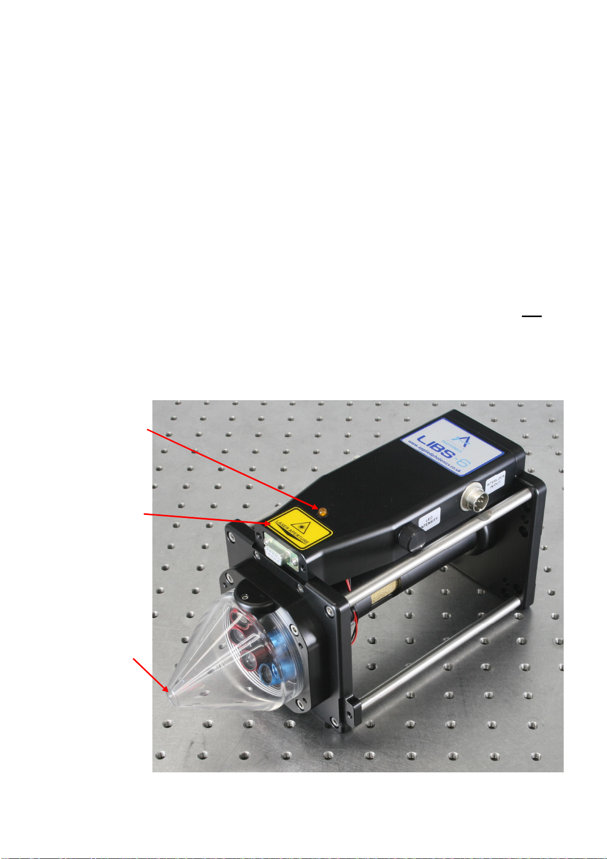
Thedoorofthesamplechamberisequipped withadualelectricalinterlock switchwhichisdesigned to
preventactivationofthelaser unless thedoorisfullyclosed. Thedoor interlock switchiselectrically
connected tothe“Interlock In/Out”portontheLIBS moduleviathe9-pin connectorlocated directly
abovethelaser aperture.The“Interlock In/Out”portconnectswiththeSpectroModule-6 (usingthe
suppliedlead) whichinturnisconnected totheinterlock circuits ofthelaser power supply.Thelaser
safetyinterface betweenthe SpectroModule-6 andthe laser power supply depends onthe make andmodel
oflaser being used. Throughoutthis User’s Manual,it is assumed thata QuantelUltra laser withICE 450
powersupplyisbeing used.
Removalofthesamplechamber fromthe LIBS module, ordisconnectionoftheInterlock In/Outlead,
willalsoactivatetheinterlock (ie. preventactivationofthe laser). The SpectroModule-6 is equippedwith
anInterlock Override facility(a keyswitch)whichallows the interlock tobedisabled sothattheLIBS
systemmaybe used withoutasamplechamber (ie. “openbeam”mode). In view ofthis, theLIBS
modules must be categorised as aClass4laserproduct since, bydesign, theproductmaybe used in
suchawaythatthelaser beamisnot contained (ie. “openbeam”mode ofoperation).If,however, the
samplechamberiscorrectly fitted totheLIBS moduleandtheInterlock Overridekeyswitchisswitched
offandthekeyremoved, thenthelaser radiationisadequately contained toClass1AccessibleEmission
Limits bythe designofthe hardware.
IMPORTANT
•READandUNDERSTAND boththisUser’s Manualandtheinstructions provided bythe
manufacturer ofthelaser before operatingtheintegrated LIBS module(LIBS-6 orLIBS-8) and
associated laser equipment.
•ENSURE thatanappropriaterisk assessmenthas beenconducted toestablishwhether ornotthe
laser safetywindows fitted tothemodular sample chambersprovide adequateprotectionagainst
exposure tolaser radiation forthe specific laseryou intend to use with the LIBSequipment.
For advice onthismatter, consult your Laser SafetyOfficer and/or Applied Photonics Ltd.
•ONLY suitablyqualified andauthorised persons should activate the Interlock Override keyswitch.
Thekeyshouldbe removed fromthekeyswitchandheldbytheLaser SafetyOfficer whenthis
feature is not required.
•ALWAYS use appropriatelaser safetyprotectiveeyewear whenoperatingthe LIBS modules and
associated laser equipmentin “open-beam”configuration–youshouldseek advice fromyour
Laser SafetyOfficer onthismatter.
•ALWAYS switchthelaser offwhennot in use andremove the keyfromthe keyswitchofthelaser
powersupplyto preventunauthorised activation.

© 1998 -2015 Applied Photonics LtdPage5 of 31
•ALWAYS thoroughly inspecttheLIBS moduleandassociated laser equipmentfordamage prior
touse. Particular attentionshouldbe givento thelaser safetywindows andthelaser safety
interlock system, whichshouldbe testedeachtimethe equipmentis used.
•NEVER allowunauthorised and/oruntrained personsoperatetheLIBS moduleandassociated
laser equipment.
•NEVER operatetheLIBS moduleandassociated laser equipmentin areas where explosivegas
mixtures maybe present.
•NEVER operatethe LIBS module andassociated laser equipmentwithanyaccess cover, panel, or
protective window removed.
•NEVER place inside thesample chamber flammableliquidsor anyother materialwhichmaygive
rise toflammable/explosive gas mixtures. Activationofthelaser under these conditionscould
resultin anexplosionleading tosevere personalinjuryand/orfire hazard. Remember thatthe
laser-induced plasmais a source ofignition.
•NEVER pointtheLIBS moduleandassociated laser equipmentat aperson(evenwithlaser
switched off), especiallytowards the eyes, evenifthe personis wearing laser safetyeyewear. The
lasershouldbe considered “active” unless thelaserpowersupplyisdeactivated and the
safety shutterfitted to thelaserhead is switched tothe CLOSED position.
•NOTE thatneither theopaque blackDelrinnozzleaperture northetransparentacrylicnozzle
aperture provide anyprotectionto theuser against exposure todirectorscattered laser radiation.
Thefunctionofthe nozzle aperture is described later in this User’s Manual.
Imageof LIBS-6 moduleshowing locationof laserwarning indicatorlight,laser apertureand warninglabel
Laserwarning
indicatorlight
Laseraperture
warning label
Laseraperture

© 1998 -2015 Applied Photonics LtdPage6 of 31
2.2Note on the lasersafety window materialused in themodularsample chambers
Thelaser safetywindow materialfitted to the sample chamber is ratedas follows:
Laser
Wavelength
(nm)
USA Standard
ANSI Z 136.1– 2000 UK &European Standard
BSEN 207:1999
Optical
Density Protection LevelR
(Q-switched laser)
1064 OD 6 L6
355 OD 5 L5
266 OD 3 L3
RL6at 1064 nmindicates aprotectionlevelofmaximumspectraltransmittance of10-6 at 1064 nmfora
pulsed laser ofpulselength10-9 – 10-7 seconds (ie.a Q-switched laser).
Thelaser safetywindows used inAppliedPhotonicsLtd’srangeofmodular samplechambersprovide
adequateprotectionagainstscattered laser lightofwavelength1064nm,355 nmand266 nmsuchthat
Class1AccessibleEmissionLimits are metif thesamplechamber isused correctly andlaser pulse
energiesare not excessivelyhigh(ie. typicallylessthan250mJwitha5-10ns pulse length). Note that
the protectivewindows are NOT suitable for use witha532 nmlaser. Giventhatthe LIBS-6 andLIBS-8
modulesmaybeused withavarietyoflasers, itistheresponsibilityoftheuser to conductarisk
assessmentto establishwhether ornotthelasersafetywindows provide adequateprotectionforthe
particular laser being used. Ifinanydoubt,youshouldconsultyour Laser SafetyOfficer and/orApplied
Photonics Ltd for advice onthismatter.
Warning –the Applied Photonics Ltd modularsamplechambersare designed specificallyforuse
with ourLIBS-6 /LIBS-8 integrated LIBSmodulesand ourLIBSCAN range ofproducts and
shouldnot be usedwith any otherlaserdevice orproduct. Ifin doubt, seek advice from the
manufacturer, Applied Photonics Ltd.
2.3Electrical
TheLIBS-6 andLIBS-8 integrated LIBS modulescontain electricalcircuitsoperatingat12 VDC ata
maximumcurrentof2.5 Amps. Accordingly,theypose noelectricshock risk. Thelaserheadand
associated power supply,however, contain electricalcircuitsoperatingatpotentiallylethalvoltage and
currentlevels. Consultthemanufacturer’sUser Manualsupplied withthelaser forfurther guidance on
the safe use ofthelaser.

© 1998 -2015 Applied Photonics LtdPage7 of 31
3General description
3.1Overview
Themain components oftheLIBS-6 integrated LIBS moduleare illustrated in thefollowing figures. The
LIBS-8 moduleisessentiallyidenticalto theLIBS-6 moduleexceptthatithaseightplasmalight
collectionchannels rather thansix.

© 1998 -2015 Applied Photonics LtdPage8 of 31
The LIBS modules provide the following features:
•Plasma light collectionlensarrayhavingarelativelylargedepth-of-field toallow efficient lightcollection even when
plasma position varies by±5 mm alongopticaxis of laserbeam.
•3-lenslaserbeam expanderwithadjustablefocus (adjustment offocal planemadebyrotating thebrass beam
expander lensholder via thecut-wayin the laserbeamtube –adjustment rangeof approx.15mm).
•Adjustablenozzleaperturewhichprovidesaconvenientmeansof settingthedistance tothesamplesurface
(adjustment rangeof approx. 15 mm).The nozzle aperture maybe removed ifthis feature is not required.
•Gas-purgeport(accepts 4mm flexiblenylon tube)which maybeusedtofeedinertgas (eg. argon, helium, nitrogen)
tothesamplesurface.Toensurepurgegas isdirectedtothe sample,itis necessarytofit the nozzle aperture.
•OptionalminiatureCCD colourvideo camerawith arrayof dimmablehigh-brightness whiteLEDs forilluminating
samplesurface.
•Lasersafetyinterlock withkeyswitchoperated overridefacility(via theSpectroModule-6 spectrometer).
•Compatiblewith theApplied Photonics Ltd rangeof modular samplechambers.
Laser
warning
light
Transparent
nozzle
aperture
Plasmalight
collection
lens holder
Threaded
ring
Front
bulkhead Camera
housing
High-
intensity
LEDs
Optics
array
Gas-purge
port
Electrical connection
(tosample chamber)
High-
intensityLED
dimmer
control
Laser
interlock
connection
Tie-bar
Laser beamtube
Lock
screw
Fibre-optic
cable
Beam
expander
Rear
bulkhead
Electronics enclosure
Cut-awaytoallow
adjustment of laser focus

© 1998 -2015 Applied Photonics LtdPage9 of 31
Front view ofLIBS-6 moduleshowingplasmalight collection lensarray,
CCD camera,LED lights,laser aperture andgaspurgeoutlet
TheabovediagramsillustratetheLIBS-6 module. Throughout theremainder ofthisUser’sManual, for
the purposes ofsimplicity, onlythe LIBS-6 module together witha QuantelBig SkyUltra laser andeither
the SC-2C or thelarger SC-2Lmodular sample chambers are described.
3.2Laserbeamexpanderand plasmalight collection optics
Theopticalconfigurationused intheintegrated LIBS modulesisillustrated schematicallyinthe
followingdiagram.Thelaser beamexpander consistsofthreelensesandisused to provide atightly
focussed laser beamat nominally90 mmfromthe aperture ofthebeamexpander (80 mm fortheLIBS-6
beamexpander). The opticaldesignisspecific to themake and modeloflaser which theLIBS module is
tobeused with–thisisspecified atthetimeoforderingoftheLIBS module. Thebrass tubular piece
whichhouses thebeamexpander lensesisthreaded sothatrotatingitcauses thefocalplane ofthelaser
beamto move. Thedesignallowsforapproximately ±7.5 mm ofadjustment,as illustrated in the
followingdiagrams. Theplasmalightcollectionopticsare angledatapprox.15.7 degrees (17.4 degrees
for the LIBS-6 module) andare designed to collect lightfromthe regionin space defined in thefollowing
diagram.Thetransparentaperture nozzleisthreaded sothatrotationcauses ittomovealongtheoptic
axisofthelaser beam–range oftravelisapproximately ±7.5 mm (itmaybe removed fromthebodyof
theLIBS modulebyunscrewing further). Themainpurpose ofthetransparentaperture nozzleisto
provide aconvenientmeansofsettingthedistance to thesamplesurface. Thenozzleaperturealso
provides containmentofthepurge gas toensure thesamplesurface andlaser-induced plasmaregionare
effectivelypurged ofatmosphericair, andprovides physicalprotectionforthelaser andplasmalight
collectionoptics (andimaging camera iffitted).
Miniature CCD
camera
(optional feature)
Circulararrayofhigh-
brightness whiteLEDlights
(optional feature)
Circulararrayofsix lens
holders –used tocollect
plasma light.Thebluelens
holders areforcollectionof
UV-VIS while the red lens
holders areforcollectionof
VIS-NIR. LIBS-8 versionhas
4 UV-VIS (blue) and4 VIS-
NIR(red) lensholders.
Laserwarning
indicator light Electricalconnection
tosamplechamber
Laserbeam expander
and outputaperture
Grubscrew forlocking
aperture nozzle(do not
over-tighten)
Gas purgeoutlet

© 1998 -2015 Applied Photonics LtdPage10of 31
3.3Attaching the LIBSmodule to a laser
TheLIBS modulesare suitableforuse withvirtuallyanycommercially-availableQ-switched Nd:YAG
laser whichhas operatingcharacteristics appropriateforLIBS. Inorder toattacheither theLIBS-6 or
LIBS-8 moduletoalaser head, itisnecessarytouse anappropriateadaptor platform.Atthetime of
writing ofthis User’s Manual,Applied Photonics Ltd supplies adaptor platformsforthefollowing lasers:
LaserProduct Adaptor Platform
Quantel Brilliant andBrilliantB AP-Brilliant
Quantel (Big Sky) Ultra CFR rangeof lasers AP-Ultra
Quantel (Big Sky) CFR200 rangeof lasers AP-CFR200
Quantel (Big Sky) CFR400 rangeof lasers AP-CFR400
Shouldyour laser not belisted above, contactApplied Photonics Ltdgiving detailsofthemakeand
modelofyour laser toenquire aboutavailabilityofa suitable adaptor platform.
Close-up viewoflaser beam focus andfield-
of-viewofplasmalightcollectionoptics
±7.5mm
±7.5mm
Adjustment rangeoffocal
plane of laser beam
(approx.±7.5 mm)
Adjustment rangeof
transparent aperturenozzle
(approx.±7.5 mm)
Transparent
aperturenozzle
Brassholder
containinglaserbeam
expanderlenses
Threadedsection
Threadedsection
LaserBeam LaserBeam
Fibre-opticcable
tospectrometer
Fibre-opticcable
tospectrometer

© 1998 -2015 Applied Photonics LtdPage11of 31
Themethod ofassemblyofthe adaptorplatformandlaser head isillustratedin thefollowing figures.
LIBS-6 modulefitted toQuantel Big SkyUltralaserheadusingAP-Ultraadaptorplatform
Quantel Big SkyUltra
CFRlaserhead
M4 x 12
Hex CapHd Screws
Qty4
AP-Ultra
adaptor platform
No6 UNC x ¾”
Hex C/S Hd Screws
Qty3
Lasersafety
shutter

© 1998 -2015 Applied Photonics LtdPage12of 31
3.4Modularsample chambers
Arange ofmodular samplechambers isavailableforuse withtheLIBS-6 /LIBS-8 modules(see table
below). These samplechambers are alsosuitable foruse withour LIBSCANrange ofproducts.Two
types (SC-2C and SC-2L) are described in more detailin the remainder ofthis User’s Manual.
SC-1 SC-2C SC-2M SC-2L
Singleaxistranslationstage,20
mmtravelperstage(manual
control).
Approx.overalldimensions: 110 x
120 x210 mm, approx. 2.0 kg
2-axistranslationstage,20 mm
travelperstage(manual control).
Approx.overalldimensions: 110 x
120 x260 mm, approx. 2.5 kg
2-axistranslationstage, 20 mm
travelperstage(manual control)
Fumeextract port. Internal LED
light.
Approx.overalldimensions: 160
x160 x260 mm, approx. 4.0 kg
3-axistranslationstage, 50 mm
travelperstage(manual control).
Fumeextractport. Internal LED
light.
Approx. overall dimensions: 280 x
250 x330 mm, 15 kg
SC-2XL XYZ-750 XYZ-2500 SC-LQ1
3-axis translationstage, 50 mm
travelperstage(manual control).
Fumeextractport.InternalLED
light.
Approx.overall dimensions:330 x
360 x430 mm, approx. 20 kg
3-axis translationstage, 75 mm
travelperstage(computer-
controlled). Fumeextractport.
Internal LED light.
Approx.overall dimensions:330 x
360 x480 mm, approx. 24 kg
3-axis translationstage, X& Y
travel = 250 mm, Z travel = 100
mm.Fumeextract port. Internal
LED light.
Approx.overall dimensions:470 x
770 x730 mm, approx. 56 kg
Modular samplechamber
designed toanalyseliquids.
Liquiddrainport inbaseof
chamber. Note: Thissample
chamber is currentlybeing
redesigned
Current rangeof modular samplechambersmanufactured byApplied Photonics Ltd
WARNING
Theaboverange ofmodular samplechambers are designed specificallyforuse withtheLIBS-6 /LIBS-8
integrated LIBS modulesortheLIBSCANrangeofmodular LIBS systems. The specifications forthe
laser safetywindows are as follows:
Laser
Wavelength
(nm)
USA Standard
ANSI Z 136.1– 2000 UK &European Standard
BSEN 207:1999
Optical
Density Protection LevelR
(Q-switched laser)
1064 OD 6 L6
355 OD 5 L5
266 OD 3 L3
RL6at 1064 nmindicates aprotectionlevelofmaximumspectraltransmittance of10-6 at 1064 nmfora
pulsed laser ofpulselength10-9 – 10-7 seconds (ie.a Q-switched laser).
Since theLIBS-6 /LIBS-8 integrated LIBS modulesmaybeused withvarious laser devices, itisthe
responsibilityoftheuser toestablishwhether theprotectionoffered bythelaser safetywindows is
adequateforthelaser being used. Ifin doubt,seek advice fromasuitablyqualified Laser SafetyOfficer
orcontactApplied Photonics Ltd before operatingthe laser equipment.

© 1998 -2015 Applied Photonics LtdPage13of 31
3.4.1SC-2C modularsample chamber
Ageneralview oftheSC-2C modular samplechamber isgivenin thefollowing figure. Thesample
chamber isequipped withabreadboard platewhichisattached toamanualtwo-axistranslationstage
(approx.20 mm travelper stage). Thebreadboard platehas anarrayofM6 tapped (blind) holes on25
mmcentres andwhichmaybeused to facilitatetheattachment ofasampleholder etc. Movement ofthe
breadboard isachieved byadjustmentoftheknobsonthesideandtopofthesamplechamber, as
illustratedbelow.
View ofSC-2C modular samplechamber
The sample chamber is equipped witha number offeatures as illustrated in the following figures.
CAD view of SC-2C modular samplechamber
Doorwith
magneticcatch
anddual electrical
interlocks
Adjustment knob for
x-axistranslation
stage
Lasersafetywindow
Adjustment knob
fory-axis
translation stage
Electricalconnection
toLIBS module
Doorwith
magneticcatch
anddual electrical
interlocks

© 1998 -2015 Applied Photonics LtdPage14of 31
CAD view of SC-2C modular samplechamber
TheSC-2C modular samplechamber isdesignedtofittotheLIBS moduleusing four M5 screws as
illustrated in thefollowing figures. Before fittingthesamplechamber totheLIBS module, ensure that
thebreadboard plateispositioned sufficiently low soas not tomake contactwiththeaperture nozzleof
theLIBS module(use they-axisadjustmentknobtolower thebreadboard plate). Be carefultofitthe
sample chamber squarelytothe LIBS module soas nottocause damage tothe electricalconnectors.
CAD views ofSC-2C modular samplechamber illustrating method of attachment toLIBS-6 module
SecureSC-2C samplechamberto
theLIBS-6 moduleusing thefour
M5 cap head screws
Adjustment knob
fory-axis
translation stage
Adjustment knob for
x-axistranslation
stage
Attachment screws
forfittingsample
chambertoLIBS
module
Doorwith
magneticcatch
anddual electrical
interlocks
Breadboard plate(with
arrayofM6 tappedholes
on25mm centres)

© 1998 -2015 Applied Photonics LtdPage15of 31
CAD views ofSC-2C modular samplechamber attachedto LIBS-6 module
3.4.2SC-2L modularsample chamber
Ageneralview oftheSC-2Lmodular samplechamber isgiveninthefollowingfigure. Thesample
chamber isequipped withabreadboard platewhichisattached to amanualthree-axistranslationstage
(50 mmtravelper stage).The breadboard plate has anarrayofM6 tapped (blind) holes on25 mm centres
andwhichmaybe used tofacilitatetheattachment ofasampleholder etc. Movementofthebreadboard
is achieved byadjustmentofthe knobs onthe sides and top ofthe sample chamber, as illustratedbelow.
View ofSC-2Lmodularsamplechamber
Doorwith
magneticcatch
anddual electrical
interlocks
Adjustment knob
fory-axis
translation stage
Lasersafety
windows
Adjustment knob
forx-axistranslation
stage
Adjustment knob
forz-axis
translation stage

© 1998 -2015 Applied Photonics LtdPage16of 31
The sample chamber is equipped witha number offeatures as illustrated in the following figures.
CAD views ofSC-2Lmodular samplechamber
CAD view of SC-2Lmodularsamplechamber
Magneticcatch
fordoor
Electricaldoor
interlock switch
Fumeextract
nozzle
Electricaldoor
interlock switch
Breadboard plate(with
arrayofM6 tappedholes
on25mm centres)
Z-axis
adjustmentknob
X-axis
adjustmentknob
Y-axis
adjustmentknob
Gooseneck
LED light
Feet suitablefor
attachmentto ametricor
imperialopticaltable

© 1998 -2015 Applied Photonics LtdPage17of 31
CAD view of rear panel of SC-2Lmodularsamplechamber
TheLIBS-8 andLIBS-6 modulesare designed to fittothetopofthesamplechamber using four M5
screws as illustrated inthefollowing figures. Before fittingtheLIBS moduletothesamplechamber,
ensure thatthebreadboard plateispositioned sufficiently lowso as not to make contact withtheaperture
nozzleoftheLIBS module. Be carefultofittheLIBS modulesquarelyto thesamplechamber so as not
to cause damage tothe electricalconnectors.
CAD view of SC-2Lmodularsamplechamberillustrating method of attachmentof LIBS-6 module
SecureLIBS-6 moduleto
SC-2Lsamplechamber
usingthefourM5cap
headscrews
SecureLIBS-6 moduleto
SC-2Lsamplechamber
usingthefourM5cap
headscrews
Label forlaser
safetywindows
Fumeextraction port –for
optionalconnection to an
externalair extractionunit
(1/2”BSPP thread)

© 1998 -2015 Applied Photonics LtdPage18of 31
CAD view of LIBS-6 modulewith Ultralaser fittedtoSC-2L modular samplechamber
Breadboard
sampletable
Ultralaser
head
head
SC-2Lmodular
samplechamber
AP-Ultra
adaptor plate
LIBS-6
module

© 1998 -2015 Applied Photonics LtdPage19of 31
Close-up viewofinsideof SC-2Lsamplechamber withLIBS-6 modulefitted
and showingalaser-induced plasmaon ametallicsample
3.5QuantelUltra ICE 450 laserpowersupply and InterlockOverride Keyswitch
See theQuantel’sinstructionsforacompletedescriptionoftheICE 450 laser power supplyandcooling
groupunit.TheelectricalconnectionsbetweentheICE 450power supply andtheSpectroModule-6are
illustratedschematicallyin thefollowing diagram.
WARNING ItisnecessarytofittheBNC clamping piece(after connectingtheinterlock BNC
connectors) in orderforthe LIBS systemtomeetClass 1 Laser Productstandards.
Schematicdiagramillustrating interlock, Q-SwitchOUTandRS232 electricalconnectionstoICE450laser powersupply
Interlock OUT
BNC port
Q-Switch
OUT
BNC port
Interlock IN
BNC port
BNC clamping piece
(used topreventunauthoriseddisconnection of
lasersafety
interlock BNC
connectors)
RS232 serial port
(labelled 1O1O1)
Fumeextract
nozzle
Gooseneck
LED light
Breadboard sample
table(witharrayof
M6 tappedholes on
25 mmcentres) Sample
Laser
plasma

© 1998 -2015 Applied Photonics LtdPage20of 31
The Interlock Overridekeyswitchlocated onthe controlpanelofthe SpectroModule-6 is used to override
thelaser safetyinterlock whentheLIBS-6 orLIBS-8 moduleisrequired to beusedin“open beam”
configuration(ie. withoutasamplechamber). To override theinterlock, thekeyswitchshouldbe turned
“on”byturningclock-wise asindicated in theimage below. Theorange /yellowLED indicatortothe
leftofthekeywitch(labelled Class4Warning) willflashcontinuously whenthekeyswitchisactivated
andthelaser isin “active” mode. Whenthekeyswitchissetto“off”, theLED willbeextinguished
indicatingthatthelaser safetyinterlock isoperating. Thekeyshouldbe removed fromtheInterlock
Override keyswitchtopreventunauthorised activationoftheinterlock override.
WARNING WhentheInterlock Override keyswitchisactivated, theLIBS systembecomes aClass 4
Laser Product, henceappropriatesafetyprocedures andprecautions MUST be adopted whenoperating
the LIBS systemin thismode.
Image illustratingInterlock Overridekeyswitchon theSpectroModule-6 control panel
LaserInterlock
OverrideKeyswitch
and warning
indicator LED
Other manuals for LIBS-6
1
This manual suits for next models
1
Table of contents