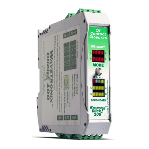
Wavetronix Click 111 Guide

1 of 23WX-501-0552 • 01.22
Using the Click 111
The Click 111 provides a contact closure interface to the Swarco controller that is used in Russian intersection
systems. A custom rack was designed by Swarco to support the Autoscope Phoenix camera contact closure
cards, and the Click 111 was designed to be a plug-in replacement to the Phoenix card. The physical size and
electrical outputs were designed based on specifications for the above mentioned Swarco system.
Physical Features
The following sections describe the physical features of the Click 111 card.
Mode
Switch
Menu
LEDs
RS-485
Connectors
Bus 2
RS-485
Connectors
Bus 1
Detection
LEDs
Rack Connector
DIP Switches
On
Off
On
Off
On
Off
On
Off
16 Contact
Closures
Click 111
PWRMFTDRD
Detection
1 2 3 4
1–4
5–8
9–12
13–16
Menu
Mode
Data: RS-485 Bus 1Control: RS-485 Bus 2
1 2 3 4 5 6 7 8
Switch 1: Baud Rates
Bus 1 Bus 2
1 2 3 4 5 6 7 8
Bus 1 Bus 2
Switch 2: Base Channel
1 2 3 4 5 6 7 8
Switch 3
1 2 3 4 5 6 7 8
Switch 4
On (1)
O (0)
5678
1 2 3 4 Bus 1
Bus 2
0 0 0 0
SW
0001 9600
0010 19200
0011 38400
0 1 0 0 57600
All others 9600
5678
1234
0 0 0 0
SW
0001 1
0010 3
0011 5
0100 7
0101 9
0 1 1 0 11
0 1 1 1 13
1 0 0 0 15
5678
1234
1 0 0 1
17
1 0 1 0 19
1 0 1 1 21
1 1 0 0 23
1 1 0 1 25
1 1 1 0 27
1 1 1 1 29
1 2 Bus1 Bus 2
3 4
S3: Channel Allocation
S2: Base ChannelS2: Base ChannelS1: Baud Rates
0 0 0 0
SW
0 0 0 1 16
0 0 1 0 14
0 0 1 1 12
0 1 0 0 10
0101 8
0110 6
0111 4
1000 2
0
2
4
6
7
8
S3: Data Enable
Cong: 0=SW, 1=HW
Bus 1: 0=Enable, 1=Dis.
Bus 2: 0=Enable, 1=Dis.
1
2
3
S4: Polarity
Cong: 0=SW, 1=HW
Ch: 0=Low, 1=High
Fault: 0=Low, 1=High
4
5
6
S4: Fault
Cong: 0=SW, 1=HW
0=Enable, 1=Disable
State: 0=Call, 1=No Call
6
8
10
12
14
1 0 0 1 0 16
All others 8 8
Ch. Alloc. Data En. Polarity Fault
Bus 1
Bus 2
Bus 1
Bus 2
Communication Ports
The Click 111 contains two independent serial communications ports, each of which can be connected to a sensor
(so two sensors can talk to each card). Each port is made up of two RJ-11 connectors, which make it simple to
daisy-chain multiple Click 111 cards together and create a RS-485 bus. The two RJ-11 RS-485 data buses can be
connected to a SmartSensor through a Click surge protection module, or through a serial data converter.
The buses are labeled as Bus 1 and Bus 2, though as both buses are identical it does not matter which is used
0517

2 of 23WX-501-0552 • 01.22
for which sensor. Be aware that this means there is no dedicated port for configuration, meaning that in order
to configure the device, you must change the wiring of your cabinet or use a single bus for both data and
configuration; in this case, data reporting will be temporarily halted during configuration. Be aware that if data isn’t
received on a Click 111 bus for ten seconds, that bus will go into a fault state.
LEDs
The faceplate of the Click 111 has six banks of LEDs.
Mode
Menu
RD TD MF PWR
1 2 3 4
Detection
1—4
5—8
9—12
13—16
The yellow LEDs in the top bank are used for navigating the front panel menu, which will be discussed later, and
have no other function. They are level 2 indicators and will be used to navigate within selected menu options.
The second bank, with four dierent colors of LEDs, is used both for navigating the front panel menu (they are
level 1 indicators used to select menu options) and for indicating the operating state of the device, as follows:
■ Yellow (RD) – Lights up when the Click 111 is receiving data on any port.
■ Green (TD) – Lights up when the device is transmitting data on any port.
■ Blue (MF) – This LED indicates whether the device is in a fault state (MF standing for master fault). If this LED is
lit up, the device is not in a fault state. If it is extinguished, one or both of the buses is in a fault state (the buses
can enter fault states independently of each other).
■ Red (PWR) – Lights up when the device has power.
The lowest four banks are for detection indication. Each LED corresponds to one channel (see the numbers next to the
LEDs for the number assignations), and when a call is placed on that channel, the LED lights up until the call ends.
Push-button
The faceplate of the Click 111 features a push-button labeled Mode. It’s used to cycle through and select menu and
configuration options.
DIP Switches
Just behind the faceplate of the Click 111, on the circuit board, is a set of DIP switches. These switches are used to
configure the Click 111 in Hardware mode.
All settings are also configurable via Software mode (front panel menu, or Click Supervisor). See the DIP Switches
section for more information.

3 of 23WX-501-0552 • 01.22
Installation and Wiring
Before you install and wire your Click 111, it’s important to understand how the buses and channels work. As
mentioned above, the Click 111 has two RS-485 buses, each of which can be connected to one sensor. Sensors
can be connected to these buses via the RJ-11 jacks on the faceplate; each bus has two RJ-11 jacks. It’s also fine to
connect a single sensor to the Click 111, but for the most part we’ll assume that two sensors will be used.
Also as mentioned above, the Click 111 is a 16-channel card: it can output 16 channels of contact closures to the
Swarco controller. These 16 channels are distributed between the two RS-485 buses. By default, they are evenly
distributed: bus 1 has eight output channels assigned to it, and bus 2 has the other eight output channels assigned
to it. (This would mean that each sensor can get eight channels’ worth of data to the Swarco controller.)
However, using configuration options on the Click 111, you can change the distribution of the channels. It must
always be in increments of two, allowing the following combinations:
Sensor 1 Sensor 2
16 0
14 2
12 4
10 6
8 8
6 10
4 12
2 14
0 16
Note. Changing the allocation of the output channels will be covered later.
So as long as one of these options suits your needs for output channels, using a single Click 111 as outlined below
will work just fine.
1. If you’re using hardware configuration, set all DIP switches before installing Click 111 devices (this will be
covered in the DIP Switches section).
2. Insert the card into the rack.
3. Connect a patch cable from one of the RJ-11 jacks labeled Bus 1 on the faceplate of the device to the surge
protector (Click 200, 222 or 223) being used for one of your two sensors.
4. Connect a second patch cable to one of the RJ-11 jacks labeled Bus 2 to the surge protector being used for
your second sensor.
But what do you do if both of your sensors need more than eight channels, and therefore none of the options in the
bulleted list above suit your needs? In that case, your easiest option will be to use one Click 111 card per sensor.
1. If you’re using hardware configuration, set all DIP switches before installing Click 111 devices (this will be
covered in the DIP Switches section).
2. Insert two cards into the rack.
3. Connect a patch cable from one of the RJ-11 jacks on the faceplate of the first Click 111 to the surge protector
(Click 200, 222 or 223) being used for one of your two sensors.
4. Connect a second patch cable to one of the RJ-11 jacks on the faceplate of the second Click 111 to the surge
protector being used for your second sensor.

4 of 23WX-501-0552 • 01.22
And finally, what do you do if one of your sensors needs more than 16 output channels? In that case, you’ll need to use
multiple Click 111 cards and daisy-chain them together. For each sensor that has this particular problem, do the following:
1. If you’re using hardware configuration, set all DIP switches before installing Click 111 devices (this will be
covered in the DIP Switches section).
2. Insert two cards into the rack.
3. Connect a patch cable from one of the RJ-11 jacks labeled Bus 1 on the faceplate of the first Click 111 to the
surge protector (Click 200, 222 or 223) being used for your sensor.
4. Connect a second, short patch cable from the other Bus 1 jack to one of the Bus 1 jacks on the faceplate of the
second Click 111.
One of these options, or a combination thereof, should give you all the output channels you need.
For your information, below is the pinout for the 64-pin backplane connector on the the back of the Click 111.

5 of 23WX-501-0552 • 01.22
Description Pin
-DC (common) B1
-DC (common) B2
No connection B3
No connection B4
No connection B5
No connection B6
No connection B7
No connection B8
No connection B9
Channel 2, normally open B10
-DC (common) B11
No connection B12
Channel 6, normally open B13
Chassis ground B14
Channel 10, normally open B15
-DC (common) B16
Channel 12, normally open B17
Channel 14, normally open B18
-DC (common) B19
No connection B20
No connection B21
No connection B22
No connection B23
Channel 4, normally open B24
No connection B25
No connection B26
No connection B27
No connection B28
No connection B29
+DC (12–24 VDC) B30
No connection B31
-DC (common) B32
Pin Description
A1 No connection
A2 No connection
A3 Channel 1, normally open
A4 No connection
A5 No connection
A6 No connection
A7 Fault Status Out
A8 No connection
A9 -DC (common)
A10 No connection
A11 -DC (common)
A12 Channel 5, normally open
A13 No connection
A14 -DC (common)
A15 Channel 9, normally open
A16 Channel 11, normally open
A17 Channel 3, normally open
A18 Channel 13, normally open
A19 No connection
A20 Channel 7, normally open
A21 Channel 15, normally open
A22 Channel 16, normally open
A23 -DC (common)
A24 No connection
A25 No connection
A26 No connection
A27 No connection
A28 No connection
A29 No connection
A30 No connection
A31 Channel 8, normally open
A32 No connection
A1
Preparing the SmartSensor
In addition to wiring the SmartSensor to the Click 111, you must also make sure that the SmartSensor is configured
correctly. Because the Click 111 device receives serial datagrams from the sensor, the sensor must be configured
to report data properly for each application. This may include loop emulation settings and/or output channel
configuration.

6 of 23WX-501-0552 • 01.22
Fault State
The Click 111 receives datagrams from the connected SmartSensor, and it’s looking for datagrams containing
detection data that’s intended for one of its output channels. If a bus does not receive such a datagram for ten
seconds, it will go into a fault state. (The fault timeout can be changed using Click Supervisor software, as will be
discussed later.) Each data bus can go into a fault state independently. The state of the output channels, when
they are in fault, can be configured as either a call or a no call.
If either of the buses go into a fault state then the master fault will be asserted. The card has one master fault
indicator (the blue LED on the faceplate of the device) and an associated output on the back connector. You can
disable failsafe for the whole card if you desire.
Configuration
The Click 111 can be configured in three ways: DIP switches, the front panel menu, and Click Supervisor.
These three dierent configuration methods can configure dierent sets of options; some of these parameters
can be set using multiple configuration methods, and some of them can only be set using one particular method.
The table below lists how each parameter may be accessed and configured.
DIP Switch Front Panel Menu Click Supervisor
Baud Rate Ye s Ye s Ye s
Base Channel Ye s Ye s Ye s
Channel Allocation Ye s Ye s Ye s
Data Enable Ye s Ye s Ye s
Channel Output Polarity Ye s Ye s Ye s
Fault Output Polarity Ye s Ye s Ye s
Fault Enable Ye s Ye s Ye s
Fault State Ye s Ye s Ye s
Autobaud No Ye s No
Reset to Defaults No Ye s Ye s
Description No No Ye s
Location No No Ye s
Device ID No No Ye s
Fault Detect Time No No Ye s
To use this configuration
feature:
Hardware Configuration
Mode
Software Configuration
Mode
Software Configuration
Mode
The final row on the table refers to configuration modes. The DIP switches can be used to choose between
Hardware and Software modes. If the switches are set to Hardware mode, the DIP switches will be used to
change configuration options. If the switches are set to Software mode, the front panel menu and Click Supervisor
will be used to change configuration options. This will be discussed in greater detail in the DIP Switches section
below.
Note. Any setting which has been configured via the DIP switches will be read-only in Click Supervisor and the
front panel menu.

7 of 23WX-501-0552 • 01.22
DIP Switches
The DIP switches are located on the circuit board behind the faceplate.
Note. When a Click 111 is delivered, all DIP switches will be in the o position.
The side of the faceplate contains information on configuring using the DIP switches, as shown in the figure below.
The Click 111 features four DIP switches labeled S1, S2, S3 and S4 on the label and in the picture above. These
switches are used to configure six dierent configurable parameters:
■ Baud rate (for buses 1 and 2)
■ Base channel (for buses 1 and 2)
■ Channel allocation
■ Data enable
■ Polarity
■ Fault
Each parameter has a way to choose between Hardware/Software modes. If Software mode is selected, the
parameter must be configured using the front panel menu or Click Supervisor. If Hardware mode is selected, the
parameter can be configured using the switches. In this case, the setting can be viewed but not changed via Click
Supervisor and the front panel menu.
Note. Certain older Click 111 devices may have slightly dierent labels; be aware that anywhere the label diers
from the text in this document, the document is correct.
Baud Rate
The baud rates for the two RS-485 buses, bus 1 and bus 2 (see the faceplate of the device for which RJ-11 jacks
are for each bus), may be independently configured using the switches on the first DIP switch, labeled S1.
Note. This parameter can also be changed using the front panel menu or Click Supervisor.

8 of 23WX-501-0552 • 01.22
The switch patterns for the two parameters are identical, but bus 1 is configured using switches 1–4 (S1:1–4) while
bus 2 is configured using switches 5–8 (S1:5–8).
S1: Bus 1 Baud Rate
1 2 3 4 Value
O O O O Software mode
O O O On 9600 bps
O O On O 19200 bps
O O On On 38400 bps
O On O O 57600 bps
All others 9600 bps
S2: Bus 2 Baud Rate
5 6 7 8 Value
O O O O Software mode
O O O On 9600 bps
O O On O 19200 bps
O O On On 38400 bps
O On O O 57600 bps
All others 9600 bps
As these tables show, if the switches are in any configuration besides the ones laid out in the first few rows of
these tables, that bus will default to 9600 bps.
If any of the switches are on (flipped up), Hardware mode is selected, meaning the baud rate will be configured
using the DIP switches, and Click Supervisor and the front panel menu will be able to display the current setting,
but not change it. If all switches are o (down), Software mode is selected and only Click Supervisor and the front
panel menu will be able to both display and change the current setting.
Base Channel
This parameter selects how the Click 111 maps the incoming sensor outputs to the card’s outputs. The setting
determines the starting sensor channel that will be mapped to the associated bus’s output channel 1.
Example. If you have this parameter set to 5 for bus 2, then sensor channel 5 will be mapped to output channel
1 on bus 2. And then the card will count up from there: if the bus has four channels allocated to it, then sensor
channel 6 will be mapped to output 2, sensor channel 7 will be mapped to output 3, and sensor channel 8 will be
mapped to output 4.
Note. This parameter can also be changed using the front panel menu or Click Supervisor.
The switch patterns for the two parameters are identical, but bus 1 is configured using switches 1–4 (S2:1–4) while
bus 2 is configured using switches 5–8 (S2:5–8).

9 of 23WX-501-0552 • 01.22
S1: Bus 1 Base Channel
1 2 3 4 Base Channel
O O O O Software mode
O O O On 1
O O On O 3
O O On On 5
O On O O 7
O On O On 9
O On On O 11
O On On On 13
On O O O 15
On O O On 17
On O On O 19
On O On On 21
On On O O 23
On On O On 25
On On On O 27
On On On On 29
S2: Bus 2 Base Channel
5 6 7 8 Base Channel
O O O O Software mode
O O O On 1
O O On O 3
O O On On 5
O On O O 7
O On O On 9
O On On O 11
O On On On 13
On O O O 15
On O O On 17
On O On O 19
On O On On 21
On On O O 23
On On O On 25
On On On O 27
On On On On 29
If any of the switches are on (flipped up), Hardware mode is selected, meaning the base channel will be
configured using the DIP switches, and Click Supervisor and the front panel menu will be able to display
the current setting, but not change it. If all switches are o (down), Software mode is selected and only Click
Supervisor and the front panel menu will be able to both display and change the current setting.
Channel Allocation
The next set of switches is used in channel allocation. This parameter is configured on the third DIP switch,
labeled S3, using switches 1–4 (S3:1–4).
Note. This parameter can also be changed using the front panel menu or Click Supervisor.
As was discussed earlier, there are sixteen output channels on the Click 111 that can be distributed in various ways
betweeen the two buses (see Table 1 and the preceding text for more information). This parameter allows you to
choose how many of those sixteen channels each bus should have.
The channels must be allocated in increments of two. So bus 1 could have 16 channels and bus 2 have 0, or bus 1
have 14 and bus 2 have 2, and so on.
S3: Channel Allocation
1 2 3 4 Bus 1 Bus 2
O O O O Software mode Software mode
O O O On 16 0
O O On O 14 2
O O On On 12 4
O On O O 10 6
O On O On 8 8

10 of 23WX-501-0552 • 01.22
O On On O 6 10
O On On On 4 12
On O O O 2 14
On O O On 0 16
All others 8 8
If any of the switches are on (flipped up), Hardware mode is selected, meaning the channel allocation will
be configured using the DIP switches, and Click Supervisor and the front panel menu will be able to display
the current setting, but not change it. If all switches are o (down), Software mode is selected and only Click
Supervisor and the front panel menu will be able to both display and change the current setting.
Data Enable
Also on this switch is the data enable parameter. This is configured on the third DIP switch, labeled S3, using
switches 6–8 (S3:6–8).
Note. This parameter can also be changed using the front panel menu or Click Supervisor.
This group of DIP switches determines whether the data buses are enabled to receive contact closure data. Each
bus can be independently enabled or disabled.
This parameter may be useful if you know a bus will not be receiving any data—for instance, if you’re only using
one sensor with your Click 111. If a bus is disabled from receiving data, then its associated channels will not go into
a fault state, even if that bus is not receiving any data.
Note. If you’ve disabled a bus from receiving data, you can still use it to configure the card using Click Supervisor.
S3: Data Enable
6 7 8 State
O – – Software mode
On – – Hardware mode
– O – Bus 1 disabled
– On – Bus 1 enabled
– – O Bus 2 disabled
– – On Bus 2 enabled
Dashes in the table indicate that the state of those switches don’t aect that particular setting.
If switch 6 is on (flipped up), Hardware mode is selected, meaning that the data enable parameter will be
configured using the DIP switches, and Click Supervisor and the front panel menu will be able to display the
current setting, but not change it. If switch 6 is o (down), Software mode is selected and only Click Supervisor
and the front panel menu will be able to both display and change the current setting.
Warning. If you don’t have switch 6 on (flipped up) to set it to Hardware mode, anything you set on switches 7 and
8 will be ignored by the Click 111.

11 of 23WX-501-0552 • 01.22
Polarity
The next parameter the DIP switches can set is polarity. This is configured on the fourth DIP switch, labeled S4,
using switches 1–3 (S4:1–3).
Note. This parameter can also be changed using the front panel menu or Click Supervisor.
This parameter sets whether a call on an output channel is indicated by high voltage or low voltage. It can be set
for both the channel outputs and the master fault output. This setting does not aect how the LEDs on the front
panel work.
S4: Polarity
1 2 3 State
O – – Software mode
On – – Hardware mode
– O – Channel outputs: call = high
– On – Channel outputs: call = low
– – O Master fault outputs: call = high
– – On Master fault outputs: call = low
If switch 1 is on (flipped up), Hardware mode is selected, meaning that the data enable parameter will be
configured using the DIP switches, and Click Supervisor and the front panel menu will be able to display the
current setting, but not change it. If switch 1 is o (down), Software mode is selected and only Click Supervisor and
the front panel menu will be able to both display and change the current setting.
Warning. If you don’t have switch 1 on (flipped up) to set it to Hardware mode, anything you set on switches 2 and
3 will be ignored by the Click 111.
Fault
The last parameter the DIP switches can set is fault settings. These are configured on the fourth DIP switch,
labeled S4, using switches 4–6 (S4:4–6).
Note. These parameters can also be changed using the front panel menu or Click Supervisor.
These switches configure two options for the fault function:
■ Global fault enable/disable for the entire card – If this switch is on, then no faults will be indicated.
■ Fault state: call or no call – This configures whether a fault produces a call or a no-call on output channels
whose bus has gone into failsafe. If this switch is o, then when a bus goes into fault, the channel outputs will be
represented by a call (which may be a high voltage or a low voltage depending on the card’s polarity setting). If
this switch is on, then a bus fault will cause the corresponding channels to go into a no-call state.
S4: Fault
4 5 6 State
O – – Software mode
On – – Hardware mode
– O – Fault state disabled
– On – Fault state enabled
– – O Fault state = call
– – On Fault state = no call

12 of 23WX-501-0552 • 01.22
If switch 4 is on (flipped up), Hardware mode is selected, meaning that the data enable parameter will be
configured using the DIP switches, and Click Supervisor and the front panel menu will be able to display the
current setting, but not change it. If switch 4 is o (down), Software mode is selected and only Click Supervisor
and the front panel menu will be able to both display and change the current setting.
Warning. If you don’t have switch 4 on (flipped up) to set it to Hardware mode, anything you set on switches 5
and 6 will be ignored by the Click 111.
Front Panel Menu
The front panel of the device features a push-button and six banks of LEDs for on-device configuration and monitoring.
The lower four banks of LEDs, labeled Detection, light up when there is a call on their associated channel.
The two upper banks of LEDs, labeled Menu, and the first push-button, labeled Mode Switch, are used for navigating
through Menu mode. This section will cover how to use these features and the menu to configure the Click 111.
The multicolored bank of LEDs will be referred to as Level 1 and is used is selecting menu options. The yellow
bank will be referred to as Level 2 and is used in configuring the menu options.
Mode
Menu
RD TD MF PWR
1 2 3 4
Detection
1—4
5—8
9—12
13—16
Note. The multicolored LEDs also function as activity/status indicators. These functions, outlined in the Physical
Features section, are only executed when the device is not in Menu mode. In this case, the yellow bank of LEDs
(Level 2) remains o.
Navigating through the Menu
The mode switch push-button is used to enter Menu mode. The following outlines the basic steps you perform to
use the menu:
1. Press and hold the mode switch to enter Menu mode. The Level 1 LEDs will start to light up to indicate that
the device is cycling through all menu options (specifics on these menu options, and which LEDs and LED
combinations represent them, will be covered later in this section).
2. Release the mode switch when you reach the desired menu option. (Pressing and holding again will resume
cycling through menu options.)
3. Quickly press and release the mode switch to select the current menu option. Once it’s selected, the Level 2
LEDs will start to let you configure the options for the selected menu option.
4. Press and hold the mode switch to cycle through the submenu. The Level 2 LEDs will light up to indicate that
the device is cycling though all configuration options (specifics on these configuration options, and which LEDs

13 of 23WX-501-0552 • 01.22
and LED combinations represent them, will be covered later).
5. Release the mode switch once the desired configuration option is reached.
6. Quickly press and release the mode switch to select the current configuration option. The device will exit Menu
mode, and either the selected function will run or the selected configuration will be set and saved to the device.
Inactivity of one minute on the mode switch will exit menu mode and resume normal operation.
Front Panel Menu Options
The following figure shows the menu and configuration options available from the front panel menu. This label is
also printed on the side of the Click 111 (on the opposite side from the DIP switches).
As shown above, the menu options are displayed on the Level 1 LEDs and the configuration parameters are
displayed on the Level 2 LEDs.
If a configuration parameter has been set using the DIP switches (meaning that parameter is currently set to
Hardware mode), you cannot change it using the front panel menu. After selecting that particular menu option
from the Level 1 LEDs, the Level 2 LEDs will display the configuration option set in the DIP switches and will not
allow you to switch from that option. The only way to exit at this point is to press the push-button once.
Note. Certain older Click 111 devices may have slightly dierent labels; be aware that anywhere the label diers
from the text in this document, the document is correct.
Bus Data Enable
The first parameter on the menu label is bus data enable. To select this parameter, release the push-button when
the yellow LED in the comes on.

14 of 23WX-501-0552 • 01.22
Note. This parameter can also be changed using the DIP switches or Click Supervisor.
This group of DIP switches determines whether the data buses are enabled to receive contact closure data. Each
bus can be independently enabled or disabled.
This parameter may be useful if you know a bus will not be receiving any data—for instance, if you’re only using
one sensor with your Click 111. If a bus is disabled from receiving data, then its associated channels will not go into
a fault state, even if that bus is not receiving any data.
Note. If you’ve disabled a bus from receiving data, you can still use it to configure the card using Click Supervisor.
A disabled output will never enter the detection state, and will never indicate a fault condition. Any combination
of outputs can be enabled. Due to limited space on the side label, not all combinations of enabled and disabled
channels are listed (see the table below).
Level 1 LEDs Bus Data Enable
Level 2 LEDs
Bus 1 & 2 Data Disabled
Bus 1 Data Enabled, Bus 2 Data Disabled
Bus 1 Data Disabled, Bus 2 Data Enabled
Bus 1 & 2 Data Enabled (Default) LED o
Cancel and exit menu LED on
See the Navigating through the Menu and the Menu Operation Example sections for how to configure this parameter.
Because this parameter can also be set by the DIP switches, you may need to ensure that the DIP switches are
set to Software configuration mode; if they are set to Hardware, the front panel menu will be able to display but
not change these settings.
Autobaud
The second option on the front panel menu label is the autobaud function. This option is indicated by the green
LED coming on solid.
Note. The autobaud function can only be accessed here, on the front panel menu.
This function initiates an autobaud on the RS-485 buses (you will select which bus to autobaud on the Level
2 LEDs). An autobaud will stop data reporting on the selected port and attempt to communicate with the
SmartSensor at all supported baud rates.
Level 1 LEDs Autobaud
Level 2 LEDs
Autobaud on bus 1
Autobaud on bus 2 LED o
Cancel and exit menu LED on
See the Navigating through the Menu and the Menu Operation Example sections for how to configure this parameter.

15 of 23WX-501-0552 • 01.22
If the Click 111 is successful in communicating with a SmartSensor, it will display the baud rate found, using the
same Level 2 LED system used in selecting the baud rate (covered in the Baud Rate section and the table below).
After a short time of displaying the autobaud results, the menu will return to normal operation.
If the autobaud fails, all four Level 2 LEDs will flash once, and then the menu will return to normal operation.
Note. If the baud rate of either of the RS-485 buses was configured using the DIP switches (so that parameter is
set to Hardware mode), the Level 2 LED configuration options for that bus will not be displayed (the LED option
will never come on). If both RS-485 buses are configured using the DIP switches, the Level 1 LED menu option for
autobaud will not be displayed (the green LED option will never come on).
Baud Rate (Bus 1 and 2)
The next parameters we’ll talk about allow you to manually set the baud rate of the two RS-485 buses. Bus 1 comes up
first, with the green and yellow LEDs coming on together; bus 2 comes up second, with the blue LED glowing solid.
Note. This parameter can also be changed using the DIP switches or Click Supervisor.
Level 1 LEDs Baud rate for bus 1
Baud rate for bus 1
Level 2 LEDs
9600 bps (default)
19200 bps
38400 bps
57600 bps LED o
Cancel and exit menu LED on
Navigating through the Menu and the Menu Operation Example sections for how to configure this parameter.
Because this parameter can also be set by the DIP switches, you may need to ensure that the DIP switches are
set to Software configuration mode; if they are set to Hardware, the front panel menu will be able to display but
not change these settings.
Base Channel
The next parameter on the front panel menu label is the base channel. This can be set independently for the two
buses. To select this parameter for bus 1, release the push-button when the yellow and blue LEDs both come on
solid; for bus 2, release the push-button when the green and blue LEDs both come on solid.
Note. This parameter can also be changed using the DIP switches or Click Supervisor.
This parameter selects how the Click 111 maps the incoming sensor outputs to the card’s outputs. The setting
determines the starting sensor channel that will be mapped to the associated bus channel 1 output.
Example. If you have this parameter set to 3 for bus 1, then sensor channel 3 will be mapped to output channel
1 on bus 1. And then the card will count up from there: if the bus has four channels allocated to it, then sensor
channel 4 will be mapped to output 2, sensor channel 5 will be mapped to output 3, and sensor channel 6 will be
mapped to output 4.

16 of 23WX-501-0552 • 01.22
Level 1 LEDs Base channel for bus 1
Base channel for bus 2
Level 2 LEDs
Channel 1
Channel 3
Channel 5
Channel 7
Channel 9
Channel 11
Channel 13
Channel 15
Channel 17
Channel 19
Channel 21
Channel 23
Channel 25
Channel 27 LED o
Cancel and exit menu LED on
See the Navigating through the Menu and the Menu Operation Example sections for how to configure this parameter.
Because this parameter can also be set by the DIP switches, you may need to ensure that the DIP switches are
set to Software configuration mode; if they are set to Hardware, the front panel menu will be able to display but
not change these settings.
Channel Allocation
The next parameter on the front panel menu label is channel allocation. To select this parameter, release the push-
button when the yellow, green and blue LEDs all come on solid.
Note. This parameter can also be changed using the DIP switches or Click Supervisor.
As mentioned earlier, the Click 111 device has sixteen output channels that can be distributed in various ways betweeen
the two buses. This parameter allows you to choose how many of those sixteen channels each bus should have.
The channels must be allocated in increments of two. So bus 1 could have 16 channels and bus 2 have 0, or bus 1
have 14 and bus 2 have 2, and so on.

17 of 23WX-501-0552 • 01.22
Level 1 LEDs Bus 1 Bus 2
Level 2 LEDs
16 channels 0 channels
14 channels 2 channels
12 channels 4 channels
10 channels 6 channels
8 channels 8 channels
6 channels 10 channels
4 channels 12 channels
2 channels 14 channels LED o
0 channels 16 channels LED on
See the Navigating through the Menu and the Menu Operation Example sections for how to configure this parameter.
Because this parameter can also be set by the DIP switches, you may need to ensure that the DIP switches are
set to Software configuration mode; if they are set to Hardware, the front panel menu will be able to display but
not change these settings.
Channel Ouput Polarity
The next parameter on the front panel menu label is channel output polarity. To select this parameter, release the
push-button when the red LED comes on solid.
Note. This parameter can also be changed using the DIP switches or Click Supervisor.
This parameter lets you choose the polarity of the calls placed by the Click 111. A call can be indicated by either
high voltage or low voltage, depending on how you configure the device. The Channel Output Polarity parameter
aects both buses.
Level 1 LEDs Channel Output Polarity
Level 2 LEDs
High asserted
Low asserted LED o
Cancel and exit menu LED on
See the Navigating through the Menu and the Menu Operation Example sections for how to configure this parameter.
Because this parameter can also be set by the DIP switches, you may need to ensure that the DIP switches are
set to Software configuration mode; if they are set to Hardware, the front panel menu will be able to display but
not change these settings.
Fault Ouput Polarity
The next parameter on the front panel menu label is fault output polarity. To select this parameter, release the
push-button when the yellow and red LEDs come on solid.
Note. This parameter can also be changed using the DIP switches or Click Supervisor.

18 of 23WX-501-0552 • 01.22
This parameter is much like channel output polarity, except that it aects the polarity of calls sent not based on
detection but based on the Click 111 going into a fault state. When the device goes into a fault state it will send a call
on the master fault output; this parameter allows you to choose whether that call is high voltage or low voltage.
Level 1 LEDs Fault Output Polarity
Level 2 LEDs
High asserted
Low asserted LED o
Cancel and exit menu LED on
See the Navigating through the Menu and the Menu Operation Example sections for how to configure this parameter.
Because this parameter can also be set by the DIP switches, you may need to ensure that the DIP switches are
set to Software configuration mode; if they are set to Hardware, the front panel menu will be able to display but
not change these settings.
Fault Enable
The next parameter on the front panel menu label is fault enable. To select this parameter, release the push-button
when the green and red LEDs come on solid.
Note. This parameter can also be changed using the DIP switches or Click Supervisor.
This parameter lets you choose whether the device will go into a fault state at all. If faults are disabled, the device
will never go into a fault state.
Level 1 LEDs Fault Enable
Level 2 LEDs
Faults enabled (default)
Faults disabled LED o
Cancel and exit menu LED on
See the Navigating through the Menu and the Menu Operation Example sections for how to configure this parameter.
Because this parameter can also be set by the DIP switches, you may need to ensure that the DIP switches are
set to Software configuration mode; if they are set to Hardware, the front panel menu will be able to display but
not change these settings.
Fault State
The next parameter on the front panel menu label is fault state. To select this parameter, release the push-button
when the yellow, green and red LEDs come on solid.
Note. This parameter can also be changed using the DIP switches or Click Supervisor.
This parameter lets you choose what happens when the device goes into a fault state: whether that means a call
is placed or no call is placed on the channel outputs whose bus has gone into a fault state.

19 of 23WX-501-0552 • 01.22
Level 1 LEDs Fault State
Level 2 LEDs
Call (default)
No call LED o
Cancel and exit menu LED on
See the Navigating through the Menu and the Menu Operation Example sections for how to configure this parameter.
Because this parameter can also be set by the DIP switches, you may need to ensure that the DIP switches are
set to Software configuration mode; if they are set to Hardware, the front panel menu will be able to display but
not change these settings.
Reset to Default Settings
The final option that comes up in the menu is Reset to Default Settings. To select this function, release the mode
switch when the red LED starts flashing.
Note. This parameter can only be configured using the DIP switches.
This function will restore all configuration settings to factory defaults, even those parameters not configured using
the front panel menu.
Level 1 LEDs Reset to Default Settings
Reset to default settings LED o
Cancel and exit menu LED on
See the Navigating through the Menu and the Menu Operation Example sections for how to view this parameter.
After the Click 111 has reset to factory defaults, it will check the DIP switches; if any of them are set to Hardware
mode, it will apply those settings to the parameter in question. If resetting to factory defaults doesn’t change
certain settings the way you expected it to, check the DIP switches to see if they are causing settings to be
changed to something other than the default.
Click Supervisor
Click Supervisor is the only way to configure non-data path type parameters such as the description, location, and
device ID, as well as the failsafe timeout parameter.
Note. Some of the parameters mentioned below can only be configured in Click Supervisor. Others can be
configured by the front panel menu and/or the DIP switches. In the case of the DIP switches, if that parameter is
set to Hardware mode, it will be grayed out in Click Supervisor, meaning you can view but not change the setting.
If you would like to set it using Click Supervisor, you will have to flip those switches on the device.
The Click 111 can be configured using the Expert driver (see the figure below).

20 of 23WX-501-0552 • 01.22
After you have made configuration changes on the driver and saved it to the Click device, the word “current” will
appear after it to indicate the driver is currently loaded onto the device.
The Backups option can be used to read configurations that have previously been saved to a file.
Expert Driver
The Expert driver contains two tabs, System and Diagnostics; the System tab is then subdivided further.
The System > General tab lets you change general information about your device. The tab has the following
parameters (see the figure and table below):
Note. This parameter can only be configured using Click Supervisor.
Setting Description
Module Allows you to enter a name and description of the device.
Driver Names the driver you are currently working with.
Description Shows a description of the device being configured. This is only for your information and does not
aect the operation of the device.
Location Displays the location of the device being configured. This is only for your information and does
not aect the operation of the device.
Serial Number Displays the serial number of your device. This information cannot be changed.
Table of contents
Other Wavetronix Industrial Electrical manuals
Popular Industrial Electrical manuals by other brands

Wisi
Wisi COMPACT LR 54 E2000 operating instructions

Murata
Murata GRM188R61E475ME11 Series Reference sheet

Murata
Murata GRM32ED71A476KE15 Series Reference sheet

Baldor
Baldor BC145 Installation and operating manual

Murata
Murata GRM155C80J105KE15 Series Reference sheet

Ingersoll-Rand
Ingersoll-Rand 9/230 Operation and maintenance manual