Aputure NOVA P300c User manual

Product Manual
English
NOVA P300c

-1-
Thank you for purchasing Aputure® NOVA P300c.
The Aputure NOVA P300c is a color panel lamp with wide
color gamut.
Detailed product manual can be found on www.aputure.com .
Foreword
IMPORTANT SAFETY INSTRUCTIONS
Bsica safety precautions should always be followed while
using the unit, as bellowing:
1. Please read and understand these instructions before using
it.
2. Close supervision is necessary when the fixture is used or
near to children, Please don’t put it unattended while
normally operating
3. Care must be taken of burning could occur from touching
hot surface.
4. Don’t operate the fixture if a cord is damaged or the fixture
has been dropped or damaged - until it has been examined
by qualified service personnel.
5. Position any power cables such that they will not be tripped
over, pulled, and don’t touch them with hot surfaces.
6. If an extension cord is necessary, a cord with an amperage
rating at least equal to that of the fixture should be used.
Cords rated for less amperage than the fixture may
overheat.
7. Always unplug the lighting fixture from the electrical outlet
before cleaning and servicing, or when not in use. Never
yank the cord to remove the plug from the outlet.

-2-
8. Let the lighting fixture cool completely before storing.
9. To reduce the risk of electric shock, don’t immerse this
fixture in water or any other liquid.
10. To reduce the risk of electric shock, don’t disassemble
this fixture. Contact Aputure Customer Service or take it
to qualified service personnel when service or repair
work is required. Incorrect reassembly may cause electric
shock when the lighting fixture is in use.
11. Use an accessory attachment not be recommended by
the manufacturer may increase the risk of fire, electric
shock, or injury to any person operating the fixture.
12. Power this fixture by connecting it to a grounded outlet.
13. Please don’t place the LED lighting fixture near any liquid
or other flammable object.
14. Only use a dry microfiber cloth to clean the product.
15. Please don’t operate the fixture in damp environment or
exist risk of short circuit or electrical shock
16. Please contact authorized service personnel while repair
is necessary . The malfunctions caused by unauthorized
disassemble are not covered under the warranty but pay
for maintenance.
17. We recommend only using the original Aputure cable
accessory. Please note that our warranty for this product
does not apply to any repair required due to any
malfunctions of unauthorized Aputure accessories,
although you may request such repairs for a fee.
18. This product is certified by RoHS, CE, KC, PSE, and FCC.
Please operate the product in full compliance with the
operation standards. Please note that this warranty does
not apply to repairs arising from malfunctions, although
you may request such repairs on a chargeable basis.

-3-
FCC Compliance Statement
19. The instructions and information in this manual are
based on thorough, controlled company testing
procedures. Further notice will not be given if the design
or specifications change.
SAVE THESE INSTRUCTIONS
This device complies with Part 15 of the FCC Rules. Operation is subject to the
following two conditions:
(1) This device may not cause harmful interference.
(2) This device must accept any interference received, including interference that may
cause undesired operation.
Warning:
Changes or modifications not expressly approved by the party responsible
for compliance could void the user's authority to operate the equipment.
NOTE:
This equipment has been tested and found to comply with the limits for a Class
B digital device, pursuant to Part 15 of the FCC Rules. These limits are designed to
provide reasonable protection against harmful interference in a residential installation.
This equipment generates, uses, and can radiate radio frequency energy and, if not
installed and used in accordance with the instructions, may cause harmful interference
to radio communications. However, there is no guarantee that interference will not
occur in a particular installation. If this equipment does cause harmful interference to
radio or television reception, which can be determined by turning the equipment off
and on, the user is encouraged to try reorient or relocate the receiving antenna.
Increase the separation between the equipment and receiver.
Connect the equipment into an outlet on a circuit different from that to which the
receiver is connected.
Consult the dealer or an experienced radio/TV technician for help.
This device has been evaluated to meet general RF exposure requirements.
RF Warning Statement:
-4-
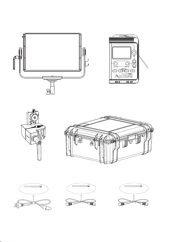
Components List
Please make sure all accessories listed below are completed before using.
If not, please contact with your sellers immediately.
Nova P300c
Lamp Head (1 pc)
Control Box
(1 pc)
Lightning Clamp
(1 pc) Nova P300c Custom Hard Shell
(Available in Kit/Sold Separately) (1pc)
Paracord
Strap(1 pc)
5-Pin Male-to-Female
XLR Head Cable (3m) (1 pc)
Neutrik® powerCON AC
Power Cable (6m) (1 pc)
Cable Tie Cable Tie
5-Pin Male-to-Female
XLR Head Cable (0.6m) (1 pc)
Cable Tie

-5-
Product Details
2. Controller box
1. Light
Paracord Strap Plate
Green-Magenta / Saturation
/ Tertiary Control Knob
USB Port
CCT / Hue / Secondary
Control Knob
Dual Junior/Baby Pin
Small text underneath:
(1-1/18in. / 28mm
| 5/8in / 16mm)
T-Handle Storage Hole
Control Box Input
Smaller Text:
(5-pin Male XLR)
Neutrik® powerCON
AC Power Input
Battery Input
Smaller text:
(3-Pin Male XLR)
T-Handle
/ Baby Pin
Mounting Screw
Disk Brake
Handle
Yoke
Fixed Diffusion
Panel
Cable Relief Hook
Carrying Handle
/Floor Stand
Quick-Release
"Lightning Clamp"
Receiver
Menu Button
Preset Buttons
Light Mode
Button
Intensity /
Main Control Knob
OLED Display
"Lightning Clamp"
Quick-Release Plate
Power Button
Accessory
Slot
-6-
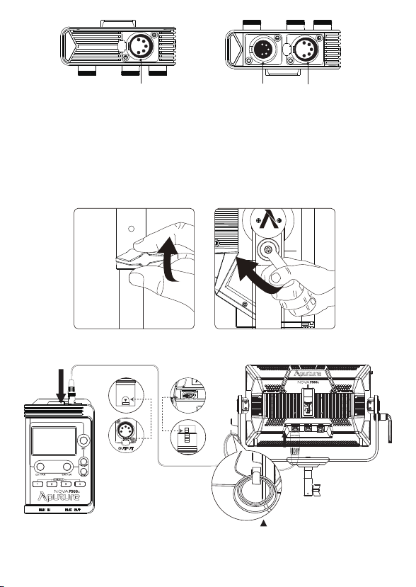
Installations
1. Setting Up Your Light
* Hang the cable from the head cable
relief hook to manage and reduce
tension on the cable.
** Disconnect the XLR head cable by pushing down on the locking tabs on the female XLR connectors, then
remove the cable.
2. Connect the light to the control box
Baby Pin (5/8in. / 16mm)
Mount the lamp head onto a light stand, then fix it in place by tightening the T-Handle
on the mounting column. Then loosen/tighten the handbrake locking mechanism on
the yoke to adjust the tilt of the fixture.
Junior Pin
Remove the T-Handle from the Junior Pin and screw it into the T-Handle Storage Hole
on the yoke. Place the light into the Junior Pin Receiver on the stand, and tighten down
the T-Handle on the receiver.
Connect the light to the control box with a 5-Pin Male-to-Female XLR cable (3m or 0.6m)
as shown below.
DMX IN Port DMX OUT Port
5-Pin Female XLR Control Box Input
PUSH
PUSH
XLR Locking Tab
XLR Locking SlotXLR Locking Slot
XLR Locking Tab
PUSH
PUSH
12
3
4
5
-7-
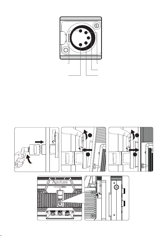
* The lamp controller interface schematic is shown in the pictures below:
Ground Signal Pin-A
Signal Pin-B
18V
Power-Ground
3. Instructions for the Lightning Clamp
1) Clamp the Lightning Clamp onto a light stand.
2) To attach the control box, rotate the release lever to unlock the
quick-release baseplate, then mount the control box onto the Lightning
Clamp (the release lever will automatically spring back).
3) To remove the control box, grasp it firmly, then unlock the quick-release
plate by turning the release lever, and detach the control box.
4) For the Lightning Clamp Receiver on the back of the lamp head,the using
method of fixing is similar with the Lightning Clamp.
1
2
1
2
-8-
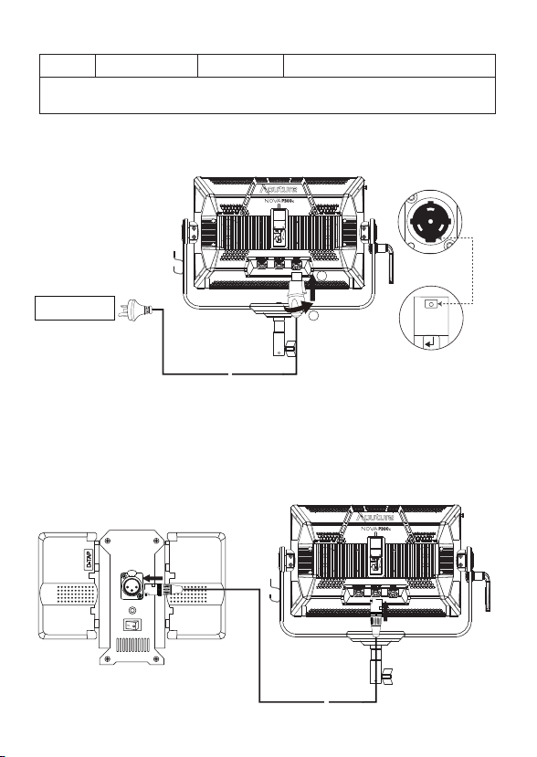
1) Powered by AC
4. Powering up the Light
To disconnect the Neutrik® powerCON cable, pull back on the yellow release
tab on the cable connector, and rotate the connector counterclockwise.
Neutrik® powerCON
Male Connector
Neutrik® powerCON Female
Locking Connector
1
2
AC 100V-240V
~
~
PUSH
Sizes (L*W*H)
Weight
* The Quick-Release "Lightning Clamp" can clamp onto square or round pipe with a
diameter between 2-5cm or 0.79-1.97in.
670g / 1.48lbs 10.35x8.74x12.5cm / 4.07x3.44x4.92in
Specifications
2) Powered by Battery
You can also power this light via DC 24V-48V Power from a 3-pin XLR. This
can be done via our an Aputure Battery Power Station that supports 48V
output, or other power stations or block batteries that are capable of
outputting the same voltage.
Power Supply Box
PUSH
~
~
-9-
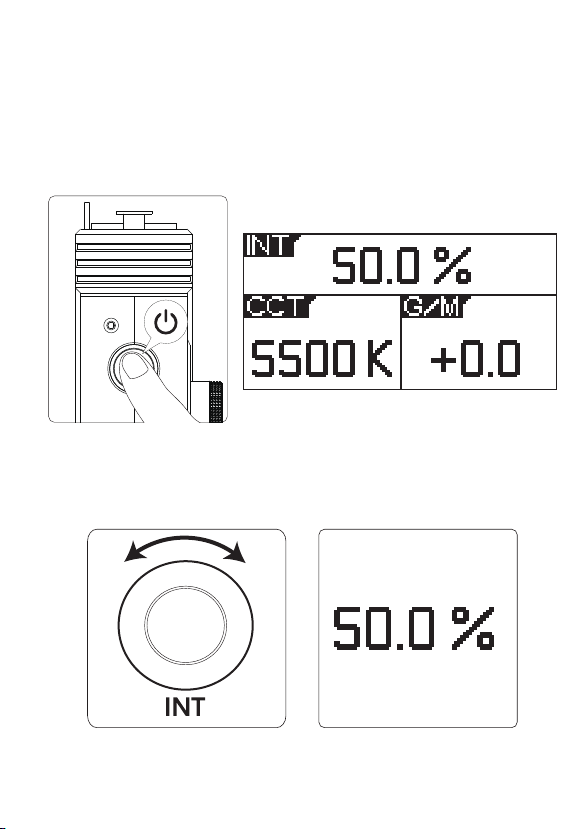
1. Turning on the Light
Operation Instructions
After connecting the lamp head to an appropriate power source, connect
the lamp head and control box with one of the included 5-Pin
Male-to-Female XLR Head Cables. Press the power button on the side of the
control box to turn the light on and off.
2.1. Rotate the Intensity (INT) Control Knob to adjust the intensity of the
light from 0-100%.
2. Manual Control
-+
Table of contents
Popular Outdoor Light manuals by other brands

Kichler Lighting
Kichler Lighting HELEN 37536 instructions

Thorn
Thorn OXANE L installation instructions

esotec
esotec Solar Globe Light multicolor 20 operating instructions

mitzi
mitzi HL200201 ELLIS Assembly and mounting instructions

HEPER
HEPER TILA S AFX 3 Module Installation & maintenance instructions

Designplan
Designplan TRON 180 installation instructions


BEGA
BEGA 84 253 Installation and technical information

HEPER
HEPER LW8034.003-US Installation & maintenance instructions

HEPER
HEPER MINIMO Installation & maintenance instructions

LIGMAN
LIGMAN BAMBOO 3 installation manual

Maretti
Maretti TUBE CUBE WALL 14.4998.04 quick start guide

Maxim Lighting
Maxim Lighting Carriage House VX 40428WGOB installation instructions