Aqua-Chem Cleaver-Brooks CB Series Guide

SAFETY PRECAUTIONS AND
ABBREVIATIONS
Safety Precautions
It is essential to read and understand the following safety
precautions before attempting to operate the equipment.
Failure to follow these precautions may result in damage to
equipment, serious personal injury, or death. A complete
understanding of this manual is required before attempting to
start-up, operate or maintain the equipment. The equipment
should be operated only by personnel who have a working
knowledge and understanding of the equipment.
The following symbols are used throughout this manual:
!DANGER
WARNING
This symbol indicates a potentially
hazardous situation which, if not
avoided, could result in serious
personal injury, or death.
!DANGER
CAUTION
This symbol indicates a potentially hazard-
ous situation which, if not avoided, could re-
sult in damage to the equipment.
Note: This symbol indicates information
that is vital to the operation of this
equipment.
Abbreviations
Following is an explanation of the abbreviations, acronyms,
and symbols used in this manual.
AC
Alternating Current
AR Automatic Reset
ASME American Society of Mechanical Engineers
ASTM American Society of Testing and Materials
BHP Boiler Horsepower
BTU British Thermal Unit
°
C Degrees Celsius
CFH Cubic Feet per Hour
Cu Ft Cubic Feet
DC Direct Current
°
F Degrees Fahrenheit
FM Factory Mutual
FS Flame Safeguard
ft Feet
GPM Gallons per Minute
Hd Head
HT Height
HTB High Turndown Burner
HZ Hertz
In H
2
O Inches of Water
IRI Industrial Risk Insurance
Lb Pound
LWCO Low-Water Cut-Off
M Million
MFD Micro-Farad
MR Manual Reset
NEC National Electric Code
No. Number
pH Measure of the degree of acid or base of a
solution
P/N Part Number
PPM Parts Per Million
PR Program Relay
psi Pounds Per Square Inch
SAE Society of Automotive Engineers
scfh Standard Cubic Feet per Hour
T Temperature
TC Temperature Control
TI Temperature Gauge

MODEL CB, CB-LE
PACKAGED BOILER
Operation, Service, and Parts Manual
125 through 200 HP
Fuel: Light Oil, Heavy Oil Gas or Combination
Please direct purchase orders for replacement manuals to your local Cleaver-Brooks authorized representative
Manual Part No. 750-184
8/98 Printed in U.S.A.
Cleaver-Brooks 1998
NOTE: If you have a CB-HAWK
Boiler Management Control
System, refer to CB-HAWK Installation, Operating and Service
Manual No. 750-133 during initial start up, and when referenc-
ing Chapters 5, 6, and 7 in this manual.

i
TO:
Owners, Operators and/or Maintenance Personnel
This operating manual presents information that will help to properly operate and care for the equipment. Study its contents
carefully. The unit will provide good service and continued operation if proper operating and maintenance instructions are fol-
lowed. No attempt should be made to operate the unit until the principles of operation and all of the components are thoroughly
understood. Failure to follow all applicable instructions and warnings may result in severe personal injury or death.
It is the responsibility of the owner to train and advise not only his or her personnel, but the contractors' personnel who are ser-
vicing, repairing or operating the equipment, in all safety aspects.
Cleaver-Brooks equipment is designed and engineered to give long life and excellent service on the job. The electrical and me-
chanical devices supplied as part of the unit were chosen because of their known ability to perform; however, proper operating
techniques and maintenance procedures must be followed at all times. Although these components afford a high degree of pro-
tection and safety, operation of equipment is not to be considered free from all dangers and hazards inherent in handling and
firing of fuel.
Any "automatic" features included in the design do not relieve the attendant of any responsibility. Such features merely free
him of certain repetitive chores and give him more time to devote to the proper upkeep of equipment.
It is solely the operator’s responsibility to properly operate and maintain the equipment. No amount of written instructions can
replace intelligent thinking and reasoning and this manual is not intended to relieve the operating personnel of the responsibility
for proper operation. On the other hand, a thorough understanding of this manual is required before attempting to operate, main-
tain, service, or repair this equipment.
Because of state, local, or other applicable codes, there are a variety of electric controls and safety devices which vary consid-
erably from one boiler to another. This manual contains information designed to show how a basic burner operates.
Operating controls will normally function for long periods of time and we have found that some operators become lax in their
daily or monthly testing, assuming that normal operation will continue indefinitely. Malfunctions of controls lead to uneconom-
ical operation and damage and, in most cases, these conditions can be traced directly to carelessness and deficiencies in testing
and maintenance.
It is recommended that a boiler room log or record be maintained. Recording of daily, weekly, monthly and yearly maintenance
activities and recording of any unusual operation will serve as a valuable guide to any necessary investigation.
Most instances of major boiler damage are the result of operation with low water. We cannot emphasize too strongly the need
for the operator to periodically check his low water controls and to follow good maintenance and testing practices. Cross-con-
necting piping to low water devices must be internally inspected periodically to guard against any stoppages which could ob-
struct the free flow of water to the low water devices. Float bowls of these controls must be inspected frequently to check for
the presence of foreign substances that would impede float ball movement.
The waterside condition of the pressure vessel is of extreme importance. Waterside surfaces should be inspected frequently to
check for the presence of any mud, sludge, scale or corrosion.
The services of a qualified water treating company or a water consultant to recommend the proper boiler water treating practices
are essential.
The operation of this equipment by the owner and his or her operating personnel must comply with all requirements or regula-
tions of his insurance company and/or other authority having jurisdiction. In the event of any conflict or inconsistency between
such requirements and the warnings or instructions contained herein, please contact Cleaver-Brooks before proceeding.
DO NOT OPERATE, SERVICE, OR REPAIRTHIS EQUIPMENT UNLESSYOU FULLY UNDERSTAND ALL
APPLICABLE SECTIONS OFTHIS MANUAL.
DO NOT ALLOW OTHERSTO OPERATE, SERVICE, OR REPAIRTHIS EQUIPMENT UNLESSTHEY FULLY
UNDERSTAND ALL APPLICABLE SECTIONS OFTHIS MANUAL.
FAILURE TO FOLLOW ALL APPLICABLE WARNINGS AND INSTRUCTIONS MAY RESULT IN SEVERE
PERSONAL INJURY OR DEATH.
!
DANGER
WARNING

TABLE OF CONTENTS
Chapter 1
Basics of Firetube Operation
A. General. . . . . . . . . . . . . . . . . . . . . . . . . . . . . . . . . . . . . . . . . . . . . . . . . . . . . . . . . . . . . . . . . . . . . . . . 1-1
B. The Boiler. . . . . . . . . . . . . . . . . . . . . . . . . . . . . . . . . . . . . . . . . . . . . . . . . . . . . . . . . . . . . . . . . . . . . . 1-2
C. Construction. . . . . . . . . . . . . . . . . . . . . . . . . . . . . . . . . . . . . . . . . . . . . . . . . . . . . . . . . . . . . . . . . . . . 1-3
D. Steam Controls (All Fuels) . . . . . . . . . . . . . . . . . . . . . . . . . . . . . . . . . . . . . . . . . . . . . . . . . . . . . . . . 1-5
E. Hot Water Controls (All Fuels). . . . . . . . . . . . . . . . . . . . . . . . . . . . . . . . . . . . . . . . . . . . . . . . . . . . . . 1-7
F. Induced Flue Gas Recirculation Components (CB-LE) . . . . . . . . . . . . . . . . . . . . . . . . . . . . . . . . . . . 1-9
Chapter 2
Burner Operation and Control
A. The Burner . . . . . . . . . . . . . . . . . . . . . . . . . . . . . . . . . . . . . . . . . . . . . . . . . . . . . . . . . . . . . . . . . . . . . 2-1
B. Control And Component Function. . . . . . . . . . . . . . . . . . . . . . . . . . . . . . . . . . . . . . . . . . . . . . . . . . . 2-4
C. Components Common To All Boilers . . . . . . . . . . . . . . . . . . . . . . . . . . . . . . . . . . . . . . . . . . . . . . . . 2-4
D. Controls For Gas Firing . . . . . . . . . . . . . . . . . . . . . . . . . . . . . . . . . . . . . . . . . . . . . . . . . . . . . . . . . . . 2-5
E. Controls Common To Oil-Fired Boiler
(Including Combination). . . . . . . . . . . . . . . . . . . . . . . . . . . . . . . . . . . . . . . . . . . . . . . . . . . . . . . . . . . 2-8
F. Additional Controls For Heavy Oil. . . . . . . . . . . . . . . . . . . . . . . . . . . . . . . . . . . . . . . . . . . . . . . . . . 2-11
G. Controls For Combination Burners Only. . . . . . . . . . . . . . . . . . . . . . . . . . . . . . . . . . . . . . . . . . . . . 2-12
H. CombustionAir . . . . . . . . . . . . . . . . . . . . . . . . . . . . . . . . . . . . . . . . . . . . . . . . . . . . . . . . . . . . . . . . 2-12
I. Automatic Ignition. . . . . . . . . . . . . . . . . . . . . . . . . . . . . . . . . . . . . . . . . . . . . . . . . . . . . . . . . . . . . . . 2-13
J. Atomizing Air . . . . . . . . . . . . . . . . . . . . . . . . . . . . . . . . . . . . . . . . . . . . . . . . . . . . . . . . . . . . . . . . . . 2-13
K. Oil Fuel Flow - Light Oil. . . . . . . . . . . . . . . . . . . . . . . . . . . . . . . . . . . . . . . . . . . . . . . . . . . . . . . . . 2-13
L. Oil Fuel Flow - Heavy Oil . . . . . . . . . . . . . . . . . . . . . . . . . . . . . . . . . . . . . . . . . . . . . . . . . . . . . . . . 2-16
M. Gas Fuel Flow . . . . . . . . . . . . . . . . . . . . . . . . . . . . . . . . . . . . . . . . . . . . . . . . . . . . . . . . . . . . . . . . . 2-16
N. Modulating Firing . . . . . . . . . . . . . . . . . . . . . . . . . . . . . . . . . . . . . . . . . . . . . . . . . . . . . . . . . . . . . . 2-16
Chapter 3
Waterside Care And Requirements
A. General. . . . . . . . . . . . . . . . . . . . . . . . . . . . . . . . . . . . . . . . . . . . . . . . . . . . . . . . . . . . . . . . . . . . . . . . 3-1
B. Water Requirements . . . . . . . . . . . . . . . . . . . . . . . . . . . . . . . . . . . . . . . . . . . . . . . . . . . . . . . . . . . . . . 3-1
C. Water Treatment . . . . . . . . . . . . . . . . . . . . . . . . . . . . . . . . . . . . . . . . . . . . . . . . . . . . . . . . . . . . . . . . . 3-5
D. Cleaning. . . . . . . . . . . . . . . . . . . . . . . . . . . . . . . . . . . . . . . . . . . . . . . . . . . . . . . . . . . . . . . . . . . . . . . 3-5
E. Boil-out Of A New Unit. . . . . . . . . . . . . . . . . . . . . . . . . . . . . . . . . . . . . . . . . . . . . . . . . . . . . . . . . . . 3-6
F. Washing Out . . . . . . . . . . . . . . . . . . . . . . . . . . . . . . . . . . . . . . . . . . . . . . . . . . . . . . . . . . . . . . . . . . . . 3-7
G. Blowdown Steam Boiler . . . . . . . . . . . . . . . . . . . . . . . . . . . . . . . . . . . . . . . . . . . . . . . . . . . . . . . . . . 3-7
H. Periodic Inspection. . . . . . . . . . . . . . . . . . . . . . . . . . . . . . . . . . . . . . . . . . . . . . . . . . . . . . . . . . . . . . . 3-9
I. Preparation For Extended Lay-up . . . . . . . . . . . . . . . . . . . . . . . . . . . . . . . . . . . . . . . . . . . . . . . . . . . . 3-9
ii

TABLE OF CONTENTS(continued)
Chapter 4
Sequence Of Operation
A. General. . . . . . . . . . . . . . . . . . . . . . . . . . . . . . . . . . . . . . . . . . . . . . . . . . . . . . . . . . . . . . . . . . . . . . . . 4-1
B. Circuit And Interlock Controls. . . . . . . . . . . . . . . . . . . . . . . . . . . . . . . . . . . . . . . . . . . . . . . . . . . . . . 4-1
C. Sequence Of Operation - Oil Or Gas . . . . . . . . . . . . . . . . . . . . . . . . . . . . . . . . . . . . . . . . . . . . . . . . . 4-2
D. Flame Loss Sequence. . . . . . . . . . . . . . . . . . . . . . . . . . . . . . . . . . . . . . . . . . . . . . . . . . . . . . . . . . . . . 4-3
Chapter 5
Starting And Operating Instructions
A. General Preparation for Start-up - All Fuels . . . . . . . . . . . . . . . . . . . . . . . . . . . . . . . . . . . . . . . . . . . 5-1
B. Control Settings-Steam and Hot Water . . . . . . . . . . . . . . . . . . . . . . . . . . . . . . . . . . . . . . . . . . . . . . . 5-2
C. Gas Pilot . . . . . . . . . . . . . . . . . . . . . . . . . . . . . . . . . . . . . . . . . . . . . . . . . . . . . . . . . . . . . . . . . . . . . . 5-3
D. Atomizing Air. . . . . . . . . . . . . . . . . . . . . . . . . . . . . . . . . . . . . . . . . . . . . . . . . . . . . . . . . . . . . . . . . . . 5-3
E. Firing Preparations for No. 2 Oil (Series 100-200) . . . . . . . . . . . . . . . . . . . . . . . . . . . . . . . . . . . . . . 5-4
F. Firing Preparations for No. 6 Oil (Series 400-600) . . . . . . . . . . . . . . . . . . . . . . . . . . . . . . . . . . . . . . 5-6
G. Firing Preparations for Gas (Series 200-400-700). . . . . . . . . . . . . . . . . . . . . . . . . . . . . . . . . . . . . . . 5-7
H. Induced Flue Gas Recirculation Set Up. . . . . . . . . . . . . . . . . . . . . . . . . . . . . . . . . . . . . . . . . . . . . . . 5-8
I. Start-up, Operating and Shutdown - All Fuels . . . . . . . . . . . . . . . . . . . . . . . . . . . . . . . . . . . . . . . . . 5-10
J. Control Operational Tests and Checks . . . . . . . . . . . . . . . . . . . . . . . . . . . . . . . . . . . . . . . . . . . . . . . 5-11
Chapter 6
Adjustment Procedures
A. General. . . . . . . . . . . . . . . . . . . . . . . . . . . . . . . . . . . . . . . . . . . . . . . . . . . . . . . . . . . . . . . . . . . . . . . . 6-1
B. Linkage - Modulating Motor & Air Damper . . . . . . . . . . . . . . . . . . . . . . . . . . . . . . . . . . . . . . . . . . . 6-2
C. Modulating Motor . . . . . . . . . . . . . . . . . . . . . . . . . . . . . . . . . . . . . . . . . . . . . . . . . . . . . . . . . . . . . . . 6-3
D. Modulating Motor Switches Low Fire and High Fire . . . . . . . . . . . . . . . . . . . . . . . . . . . . . . . . . . . . 6-3
E. Burner Operating Controls General . . . . . . . . . . . . . . . . . . . . . . . . . . . . . . . . . . . . . . . . . . . . . . . . . . 6-4
F. Modulating Pressure Controls (Steam). . . . . . . . . . . . . . . . . . . . . . . . . . . . . . . . . . . . . . . . . . . . . . . . 6-6
G. Operating Limit Pressure Control (Steam) . . . . . . . . . . . . . . . . . . . . . . . . . . . . . . . . . . . . . . . . . . . . 6-6
H. High Limit Pressure Control - (Steam) . . . . . . . . . . . . . . . . . . . . . . . . . . . . . . . . . . . . . . . . . . . . . . . 6-6
I. Modulating Temperature Control - (Hot Water) . . . . . . . . . . . . . . . . . . . . . . . . . . . . . . . . . . . . . . . . . 6-6
J. Operating Limit Temperature Control - (Hot Water) . . . . . . . . . . . . . . . . . . . . . . . . . . . . . . . . . . . . . 6-7
K. High Limit Temperature Control - (Hot Water). . . . . . . . . . . . . . . . . . . . . . . . . . . . . . . . . . . . . . . . . 6-7
L. Low-Water Cutoff Devices. . . . . . . . . . . . . . . . . . . . . . . . . . . . . . . . . . . . . . . . . . . . . . . . . . . . . . . . . 6-7
M. CombustionAir Proving Switch . . . . . . . . . . . . . . . . . . . . . . . . . . . . . . . . . . . . . . . . . . . . . . . . . . . . 6-7
N. Atomizing Air Proving Switch. . . . . . . . . . . . . . . . . . . . . . . . . . . . . . . . . . . . . . . . . . . . . . . . . . . . . . 6-7
O. Gas Pilot Flame Adjustment . . . . . . . . . . . . . . . . . . . . . . . . . . . . . . . . . . . . . . . . . . . . . . . . . . . . . . . 6-8
P. Gas Pressure and Flow Information . . . . . . . . . . . . . . . . . . . . . . . . . . . . . . . . . . . . . . . . . . . . . . . . . . 6-9
Q. Gas Fuel CombustionAdjustment . . . . . . . . . . . . . . . . . . . . . . . . . . . . . . . . . . . . . . . . . . . . . . . . . . 6-11
R. Low-Gas Pressure Switch . . . . . . . . . . . . . . . . . . . . . . . . . . . . . . . . . . . . . . . . . . . . . . . . . . . . . . . . 6-13
S. High-Gas Pressure Switch . . . . . . . . . . . . . . . . . . . . . . . . . . . . . . . . . . . . . . . . . . . . . . . . . . . . . . . . 6-14
T. Fuel Oil Pressure and Temperature - General. . . . . . . . . . . . . . . . . . . . . . . . . . . . . . . . . . . . . . . . . . 6-14
U. Fuel Oil CombustionAdjustment . . . . . . . . . . . . . . . . . . . . . . . . . . . . . . . . . . . . . . . . . . . . . . . . . . 6-17
iii

TABLE OF CONTENTS (continued)
Chapter 6 (continued)
Adjustment Procedures
V. Burner Drawer Adjustments. . . . . . . . . . . . . . . . . . . . . . . . . . . . . . . . . . . . . . . . . . . . . . . . . . . . . . . 6-18
W. Oil Drawer Switch. . . . . . . . . . . . . . . . . . . . . . . . . . . . . . . . . . . . . . . . . . . . . . . . . . . . . . . . . . . . . . 6-18
X. Low-Oil-Temperature Switch . . . . . . . . . . . . . . . . . . . . . . . . . . . . . . . . . . . . . . . . . . . . . . . . . . . . . 6-18
Y. High-Oil-Temperature Switch . . . . . . . . . . . . . . . . . . . . . . . . . . . . . . . . . . . . . . . . . . . . . . . . . . . . . 6-18
Z. Low-Oil-Pressure Switch . . . . . . . . . . . . . . . . . . . . . . . . . . . . . . . . . . . . . . . . . . . . . . . . . . . . . . . . . 6-19
AA. Electric Oil Heater Thermostat . . . . . . . . . . . . . . . . . . . . . . . . . . . . . . . . . . . . . . . . . . . . . . . . . . . 6-19
BB. Steam Oil Heater Thermostat . . . . . . . . . . . . . . . . . . . . . . . . . . . . . . . . . . . . . . . . . . . . . . . . . . . . 6-19
CC. Hot Water Oil Heater Thermostat . . . . . . . . . . . . . . . . . . . . . . . . . . . . . . . . . . . . . . . . . . . . . . . . . 6-19
DD. Steam Heater Pressure Regulator . . . . . . . . . . . . . . . . . . . . . . . . . . . . . . . . . . . . . . . . . . . . . . . . . 6-19
Chapter 7
Trouble Shooting
. . . . . . . . . . . . . . . . . . . . . . . . . . . . . . . . . . . . . . . . . . . . . . . . . . . . . . . . . . . . . 7-1
Chapter 8
Inspection And Maintenance
A. General. . . . . . . . . . . . . . . . . . . . . . . . . . . . . . . . . . . . . . . . . . . . . . . . . . . . . . . . . . . . . . . . . . . . . . . . 8-1
B. Fireside Cleaning . . . . . . . . . . . . . . . . . . . . . . . . . . . . . . . . . . . . . . . . . . . . . . . . . . . . . . . . . . . . . . . . 8-2
C. Water Level Controls and Waterside . . . . . . . . . . . . . . . . . . . . . . . . . . . . . . . . . . . . . . . . . . . . . . . . . 8-2
D. Water Gauge Glass. . . . . . . . . . . . . . . . . . . . . . . . . . . . . . . . . . . . . . . . . . . . . . . . . . . . . . . . . . . . . . . 8-3
E. Electrical Controls . . . . . . . . . . . . . . . . . . . . . . . . . . . . . . . . . . . . . . . . . . . . . . . . . . . . . . . . . . . . . . . 8-3
F. Flame Safety Control . . . . . . . . . . . . . . . . . . . . . . . . . . . . . . . . . . . . . . . . . . . . . . . . . . . . . . . . . . . . . 8-4
G. Oil Burner Maintenance. . . . . . . . . . . . . . . . . . . . . . . . . . . . . . . . . . . . . . . . . . . . . . . . . . . . . . . . . . . 8-5
H. Gas Burner Maintenance . . . . . . . . . . . . . . . . . . . . . . . . . . . . . . . . . . . . . . . . . . . . . . . . . . . . . . . . . . 8-7
I. Motorized Gas Valve . . . . . . . . . . . . . . . . . . . . . . . . . . . . . . . . . . . . . . . . . . . . . . . . . . . . . . . . . . . . . . 8-7
J. Solenoid Valves . . . . . . . . . . . . . . . . . . . . . . . . . . . . . . . . . . . . . . . . . . . . . . . . . . . . . . . . . . . . . . . . . . 8-7
K. Air Control Damper, Linkage and Cam Spring . . . . . . . . . . . . . . . . . . . . . . . . . . . . . . . . . . . . . . . . . 8-7
L. Forced Draft Fan. . . . . . . . . . . . . . . . . . . . . . . . . . . . . . . . . . . . . . . . . . . . . . . . . . . . . . . . . . . . . . . . . 8-8
M. CB-LE Fan/Motor Cassette Removal . . . . . . . . . . . . . . . . . . . . . . . . . . . . . . . . . . . . . . . . . . . . . . . . 8-9
N. CB-LE Inspection and Adjustment . . . . . . . . . . . . . . . . . . . . . . . . . . . . . . . . . . . . . . . . . . . . . . . . . 8-10
O. CB-LE Airbox Gasket Installation. . . . . . . . . . . . . . . . . . . . . . . . . . . . . . . . . . . . . . . . . . . . . . . . . . 8-12
P. CB-LE Fan/Motor Cassette Installation . . . . . . . . . . . . . . . . . . . . . . . . . . . . . . . . . . . . . . . . . . . . . . 8-12
Q. Safety Valves . . . . . . . . . . . . . . . . . . . . . . . . . . . . . . . . . . . . . . . . . . . . . . . . . . . . . . . . . . . . . . . . . . 8-19
R. Fuel Oil Valves. . . . . . . . . . . . . . . . . . . . . . . . . . . . . . . . . . . . . . . . . . . . . . . . . . . . . . . . . . . . . . . . . 8-19
S. Air Pump and Components. . . . . . . . . . . . . . . . . . . . . . . . . . . . . . . . . . . . . . . . . . . . . . . . . . . . . . . . 8-20
T. Head Inspection and Maintenance . . . . . . . . . . . . . . . . . . . . . . . . . . . . . . . . . . . . . . . . . . . . . . . . . . 8-23
U. Refractory. . . . . . . . . . . . . . . . . . . . . . . . . . . . . . . . . . . . . . . . . . . . . . . . . . . . . . . . . . . . . . . . . . . . . 8-25
V. Sealing and Closing Inner Door and Front Head . . . . . . . . . . . . . . . . . . . . . . . . . . . . . . . . . . . . . . . 8-27
W. Lubrication . . . . . . . . . . . . . . . . . . . . . . . . . . . . . . . . . . . . . . . . . . . . . . . . . . . . . . . . . . . . . . . . . . . 8-31
X. Oil Heaters—Electric, Steam, Hot Water. . . . . . . . . . . . . . . . . . . . . . . . . . . . . . . . . . . . . . . . . . . . . 8-32
Y. Combustion. . . . . . . . . . . . . . . . . . . . . . . . . . . . . . . . . . . . . . . . . . . . . . . . . . . . . . . . . . . . . . . . . . . . 8-32
Z. Air Pump Belt. . . . . . . . . . . . . . . . . . . . . . . . . . . . . . . . . . . . . . . . . . . . . . . . . . . . . . . . . . . . . . . . . . 8-32
iv

Chapter 9
Customer Service And Parts
Front Door, Inner Door. . . . . . . . . . . . . . . . . . . . . . . . . . . . . . . . . . . . . . . . . . . . . . . . . . . . . . . . . . . . . . 3-5
Rear Head . . . . . . . . . . . . . . . . . . . . . . . . . . . . . . . . . . . . . . . . . . . . . . . . . . . . . . . . . . . . . . . . . . . . . . . . . . 6
Dry Oven & Liner Tile . . . . . . . . . . . . . . . . . . . . . . . . . . . . . . . . . . . . . . . . . . . . . . . . . . . . . . . . . . . . . . 7, 8
Impellers . . . . . . . . . . . . . . . . . . . . . . . . . . . . . . . . . . . . . . . . . . . . . . . . . . . . . . . . . . . . . . . . . . . . . . . . .9,10
Jackshafts, Mod Motor, Air Damper Linkage. . . . . . . . . . . . . . . . . . . . . . . . . . . . . . . . . . . . . . . . . . . 11-15
Burner Drawer . . . . . . . . . . . . . . . . . . . . . . . . . . . . . . . . . . . . . . . . . . . . . . . . . . . . . . . . . . . . . . . . . . 16, 17
Burner Housing. . . . . . . . . . . . . . . . . . . . . . . . . . . . . . . . . . . . . . . . . . . . . . . . . . . . . . . . . . . . . . . . . . 18, 19
Flame Control . . . . . . . . . . . . . . . . . . . . . . . . . . . . . . . . . . . . . . . . . . . . . . . . . . . . . . . . . . . . . . . . . . . 20, 21
Entrance Box & Fuses . . . . . . . . . . . . . . . . . . . . . . . . . . . . . . . . . . . . . . . . . . . . . . . . . . . . . . . . . . . . 22, 23
Front Head Electrical . . . . . . . . . . . . . . . . . . . . . . . . . . . . . . . . . . . . . . . . . . . . . . . . . . . . . . . . . . . . . 24, 25
Electric Oil Heater . . . . . . . . . . . . . . . . . . . . . . . . . . . . . . . . . . . . . . . . . . . . . . . . . . . . . . . . . . . . . . . 26, 27
Oil Emission Steam Electric Heater . . . . . . . . . . . . . . . . . . . . . . . . . . . . . . . . . . . . . . . . . . . . . . . . . . 28-30
Air Compressor /Air Line Piping . . . . . . . . . . . . . . . . . . . . . . . . . . . . . . . . . . . . . . . . . . . . . . . . . . . . 31-34
Light Oil / Air Piping Front Head. . . . . . . . . . . . . . . . . . . . . . . . . . . . . . . . . . . . . . . . . . . . . . . . . . . . 35, 36
Gas Trains . . . . . . . . . . . . . . . . . . . . . . . . . . . . . . . . . . . . . . . . . . . . . . . . . . . . . . . . . . . . . . . . . . . . . . 37, 38
Pressure Controls . . . . . . . . . . . . . . . . . . . . . . . . . . . . . . . . . . . . . . . . . . . . . . . . . . . . . . . . . . . . . . . . . . . 39
Temperature Controls . . . . . . . . . . . . . . . . . . . . . . . . . . . . . . . . . . . . . . . . . . . . . . . . . . . . . . . . . . . . . 40, 41
Water Column . . . . . . . . . . . . . . . . . . . . . . . . . . . . . . . . . . . . . . . . . . . . . . . . . . . . . . . . . . . . . . . . . . . 42, 43
v
Notes

750-184 1-1
CHAPTER 1
Basics of Firetube Operation
A. GENERAL
Firetube boilers are available for low or high pressure steam,
or for hot water applications. Firetube boilers are typically
used for applications ranging from 15 to 800 horsepower. A
firetube boiler is a cylindrical vessel, with horizontal tubes
passing through and connected to the front and rear tube
sheets. The vessel contains the water and absorbs the energy
generated from the flame. The front door and rear door
provide the seal to contain the hot combustion gasses. Baffles
designed into the doors serve to redirect the combustion
gasses through the various firetube passages. The flame
originates in the furnace. As the combustion gasses travel
down the furnace and through the various firetube channels,
heat from the flame and combustion gasses is transferred to
the water. Transferred energy develops into the required
steam or hot water. The primary purpose of the boiler is to
supply energy to the facility’s operations - for heat,
manufacturing process, laundry, kitchen, etc. The nature of
the facility’s operation will dictate whether a steam or hot
water boiler should be used.
Note: If your boiler is equipped with a CB-
HAWK
boiler management control
system, refer to CB-HAWK Installation,
Operating and Servicing Manual No. 750-
133 for information regarding controls
discussed in Chapter 1.
Figure: 1-1 Firetube Cut Away(Typical)
A. General . . . . . . . . . . . . . . . . . . . . . . . . . . . . . . . . . . 1-1
B. The Boiler. . . . . . . . . . . . . . . . . . . . . . . . . . . . . . . . 1-2
C. Construction . . . . . . . . . . . . . . . . . . . . . . . . . . . . . . 1-3
D. Steam Controls (All Fuels). . . . . . . . . . . . . . . . . . . 1-5
E. Hot Water Controls (All Fuels). . . . . . . . . . . . . . . . 1-7
F. Induced Flue Gas Recirculation Components. . . . . 1-9

Chapter 1 Basics of Firetube Operation
1-2 750-184
The general information in this manual applies directly to
Cleaver-Brooks Model CB Boilers in sizes ranging from 125
through 200 boiler horsepower for the following fuels:
Series 100 Light Oil (No. 2)
Series 200 Light Oil (No. 2) Or Gas
Series 400 Heavy Oil (No. 6) Or Gas
Series 600 Heavy Oil (No. 6) Only
Series 700 Gas Only
Note: Although the Series 400 or 600 burner
is designed and designated to burn No. 6
oil, the burner will handle grades 4 and 5
equally well, with some possible
adjustments. While the manual contains
pertinent information on No. 6 fuel oil, all
references to No. 6 fuel should be
considered applicable to all grades of heavy
oil.
The LE Option, available on Cleaver-Brooks Firetube
Boilers, reduces Nitrogen Oxide (NOx) emissions, a major
precursor to ozone pollution (smog). Carbon Monoxide (CO)
emissions also tend to be lower, due to increased turbulence
caused by the addition of the flue gases into the combustion
air stream, thereby improving combustion.
Note: For information on IFGR when firing
heavy oil, review the Operation and
Maintenance manual for Heavy Oil Isolation
750-171
The LE Option is used on Cleaver-Brooks Model CB Firetube
boilers firing either natural gas and/or light oil, and is
compatible with both hot water and steam systems.
The IFGR system mixes a portion of the relatively cool flue
gas from the exit of the fourth-pass tubes with the incoming
combustion air to reduce the furnace flame temperature,
thereby reducing NOx emissions. In this approach, the
combustion air fan handles both the combustion air and the
recirculated flue gases. Accordingly, this method is called
Induced Flue Gas Recirculation (IFGR), because the flue gas
is “induced” into the fan inlet.
The LE Option, with its various levels of IFGR systems, can
affect the selection of the combustion air fan, motor, burner,
and other components. Several different system
configurations are available, depending on the requirements
for NOx emissions and the fuels used. All systems use
similar primary components, but may have different linkage
controls, IFGR damper, fan, and motor sizes.
Always order genuine Cleaver-Brooks parts from your local
Cleaver-Brooks authorized representative.
The boiler and related equipment installation are to be in
compliance with the standards of the National Board of Fire
Underwriters. Installation should also conform to state and
local codes governing such equipment. Prior to installation,
the proper authorities having jurisdiction are to be consulted,
permits obtained, etc. All boilers in the above series comply,
when equipped with optional equipment, to Industrial Risk
Insurers (IRI), Factory Mutual (FM), or other insuring
underwriters requirements.
B.THE BOILER
The Model CB boiler is a packaged firetube boiler of welded
steel construction and consists of a pressure vessel, burner,
burner controls, forced draft fan, damper, air pump,
refractory, and appropriate boiler trim.
The horsepower rating of the boiler is indicated by the
numbers following the fuel series. Thus, CB700-200
indicates a gas-fired 200 hp boiler.
The firetube construction provides some characteristics that
differentiate it from other boiler types. Because of its vessel
size, the firetube contains a large amount of water, allowing
it to respond to load changes with minimum variation in
steam pressure.
Firetube boilers are rated in boiler horsepower (BHP), which
should not be confused with other horsepower measure-
ments.
Hot water is commonly used in heating applications with the
boiler supplying water to the system at 180
°
F to 220
°
F. The
operating pressure for hot water heating systems usually is
30 psig to 125 psig.
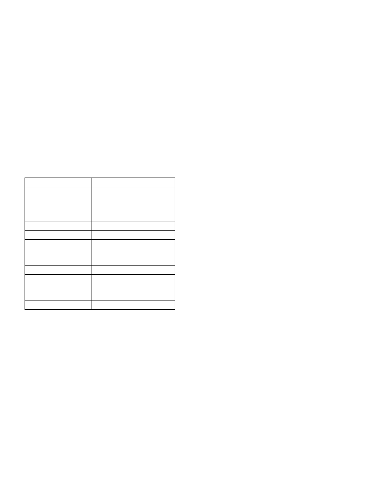
Rated Capacity 125 through 200hp
Operating Pressure Steam15-250 psig, orhigherif
specified
Hot Water 30-250 psig or
higher if specified
Fuel Oil or Gas or Combination
Ignition Automatic
Firing Full Modulation Through
Operating Ranges
Burner (Oil) (Low Pressure) Air Atomizing
Burner (Gas) Non-premix – Orificed Type
Air Damper Rotary Type
(Electrically Modulated)
Steam Trim ASME Code
Water Trim ASME Code

Basics of Firetube Operation Chapter 1
750-184 1-3
Steam boilers are designed for low pressure or high pressure
applications. Low pressure boilers are limited to 15 psig
design, and are typically used for heating applications. High
pressure boilers are typically used for process loads and can
have a design pressure of 75 to 350 psig.
Steam and hot water boilers are defined according to design
pressure and operating pressure. Design pressure is the max-
imum pressure used in the design of the boiler for the pur-
pose of calculating the minimum permissible thickness or
physical characteristics of the pressure vessel parts of the
boiler. Typically, the safety valves are set at or below design
pressure. Operating pressure is the pressure of the boiler at
which it normally operates. The operating pressure usually is
maintained at a suitable level below the setting of the pres-
sure relieving valve(s) to prevent their frequent opening dur-
ing normal operation.
The type of service that your boiler is required to provide has
an important bearing on the amount of waterside care it will
require.
!DANGER
CAUTION
Waterside care is of prime importance. For
specific information or assistance with your
water treatment requirements, contact your
Cleaver-Brooks service and parts represen-
tative. Failure to follow these instructions
could result in equipment damage
Feedwater equipment should be checked and ready for use.
Be sure that all valves, piping, boiler feed pumps, and
receivers are installed in accordance with prevailing codes
and practices.
Water requirements for both steam and hot water boilers are
essential to boiler life and length of service. Constant
attention to water requirements will pay dividends in the form
of longer life, less down-time, and prevention of costly
repairs. Care taken in placing the pressure vessel into initial
service is vital. The waterside of new boilers and new or
remodeled steam or hot water systems may contain oil, grease
or other foreign matter. A method of boiling out the vessel to
remove accumulations is described in Chapter 3.
The operator should be familiar with Chapter 3 before
attempting to place the unit into operation.
C. CONSTRUCTION
Steam boilers designed for 15 psig and hot water boilers
designed for 250
°
F at 125 psi or less are constructed in
accordance with Section IV, Power Boilers, of ASME Code.
Steam boilers designed for operating pressures exceeding 15
psig are constructed in accordance with Section 1, Power
Boilers, of the ASME Code. Hot water boilers designed for
operating temperatures above 250
°
F or 125 psi are likewise
built toASME Code.

Chapter 1 Basics of Firetube Operation
1-4 750-184
Figure: 1-2 Typical Steam Boiler - Light Oil or Gas Fired (CB)
VENT
VALVE
WATER COLUMN
WATER GLASS
DRAINVALVE
LOWWATER CUT-OFF
AND PUMP CONTROL
OPERATING PRESSURE,
HIGH LIMIT PRESSURE
AND MODULATING
PRESSURE CONTROLS
COMBUSTION AIR
PROVIDING SWITCH
CONTROL PANEL
ATOMIZING
PROVIDING
STEAM PRESSURE
GAUGE
FORCED DRAFT
FAN MOTOR
FUEL OIL
CONTROLLER
FLAME
SWITCH
AIR
DETECTOR
ATOMIZING AIR
PRESSURE
GAUGE
FLEXIBLE
OIL LINE
FLEXIBLE
AIR LINE
MODULATING
MOTOR
OIL SOLENOID
VALVES
IGNITION
TRANSFORMER
OIL
SUPPLY LINE
NOZZLE
HOLDER
OIL PIPING
TERMINAL BLOCK
OIL RETURN LINE
OIL BURNER
PRESSURE
AIR PUMP
MODULE
OIL STRAINER
GAUGE
AUXILIARY
LOWWATER CUTOFF
ATOMIZING AIR
OILTANK
MAIN GASTRAIN
PILOT GASTRAIN
MAIN GAS
BUTTERFLY VALVE
STACKTEMPERTURE
GAUGE

Basics of Firetube Operation Chapter 1
750-184 1-5
Figure: 1-3 Steam Controls
Figure: 1-5 LowWater Cut Off Pump Control
(Cutaway)
D. STEAM CONTROLS (ALL FUELS)
1. Operating Limit Pressure Control (Figure 1-3): Breaks a
circuit to stop burner operation on a rise of boiler
pressure at a selected setting. It is adjusted to stop or start
the burner at a preselected pressure setting.
2. High Limit Pressure Control (Figure 1-3): Breaks a
circuit to stop burner operation on a rise of pressure
above a selected setting. It is adjusted to stop the burner
at a preselected pressure above the operating limit
control setting. The high limit pressure control is
normally equipped with a manual reset.
3. Modulating Pressure Control (Figure 1-3): Senses
changing boiler pressures and transmits the information
to the modulating motor to change the burner firing rate
when the manual-automatic switch is set on “automatic.”
4. Low-Water Cutoff and Pump Control (Figure 1-4):
Float-operated control responds to the water level in the
boiler. It performs two distinct functions:
•Stops firing of the burner if water level lowers below the
safe operating point. Energizes the low-water light in the
control panel; also causes low-water alarm bell (optional
equipment) to ring. Code requirements of some models
require a manual reset type of low-water cutoff.
•Starts and stops the feedwater pump (if used) to maintain
water at the proper operating level (Figure 1-5).
!DANGER
CAUTION
Determine that the main and auxiliary low
water cutoffs and pump control are level af-
ter installation and throughout the equip-
ment’s operating life. Failure to follow these
instructions could result in equipment dam-
age.
1.
OPERATING
LIMIT
CONTROL
2.
HIGH
LIMIT
CONTROL
3.
MODULATING
CONTROL
12 3
Figure: 1-4 Low Water Cut Off (LWCO)

Chapter 1 Basics of Firetube Operation
1-6 750-184
5. Water Column Assembly (Figure 1-6): Houses the low-
water cutoff and pump control and includes the water
gauge glass, gauge glass shutoff cocks.
6. Water Column DrainValve (Figure 1-6): Provided so that
the water column and its piping can be flushed regularly
to assist in maintaining cross-connecting piping and in
keeping the float bowl clean and free of sediment. A
similar drain valve is furnished with auxiliary low-water
cutoff for the same purpose.
7. Water Gauge Glass DrainValve (Figure 1-7): Provided to
flush the gauge glass.
8. Vent Valve (Figure 1-7): Allows the boiler to be vented
during filling, and facilitates routine boiler inspection as
required by ASME Code.
9. Stack Temperature Gauge (Figure 1-7): Indicates flue gas
outlet temperature.
Figure: 1-6 Water Column Assembly
Figure: 1-7 LWCO and Gauge Glass
VENT
VALVE
FLUE
GAS
OUTLET
TEMP
.
GAUGE
DRAIN
VALVE
GAUGE GLASS
DRAIN VALVE
10. Auxiliary Low-water Cutoff (Figure 1-8): Breaks the
circuit to stop burner operation in the event boiler water
drops below the master low-water cutoff point. Manual
reset type requires manual resetting in order to start the
burner after a low-water condition.
Figure: 1-8 Auxiliary LowWater Cut Off

Basics of Firetube Operation Chapter 1
750-184 1-7
11. Safety Valve(s) (Figure 1-9): Prevent buildup over the
design pressure of the pressure vessel. The size, rating
and number of valves on a boiler is determined by the
ASME Boiler Code. The safety valves and the discharge
piping are to be installed to conform to the ASME code
requirements. The installation of a valve is of primary
importance to its service life. A valve must be mounted
in a vertical position so that discharge piping and code-
required drains can be properly piped to prevent buildup
of back pressure and accumulation of foreign material
around the valve seat area. Apply only a moderate
amount of pipe compound to male threads and avoid
overtightening, which can distort the seats. Use only flat-
jawed wrenches on the flats provided. When installing a
flange-connected valve, use a new gasket and draw the
mounting bolts down evenly. Do not install or remove
side outlet valves by using a pipe or wrench in the outlet.
!DANGER
WARNING
Only properly certified personnel such as
the safety valve manufacturer’s certified
representative can adjust or repair the
boiler safety valves. Failure to follow these
instructions could result in serious
personal injury or death
E. HOT WATER CONTROLS (ALL
FUELS)
1. Water Temperature Gauge (Figure 1-11): Indicates the
boiler internal water temperature.
2. Operating Limit Temperature Control (Figure 1-12):
Breaks a circuit to stop burner operation on a rise of
boiler temperature at a selected setting. It is adjusted to
stop or start the burner at a preselected operating
temperature.
3. High Limit Temperature Control (Figure 1-12): Breaks a
circuit to stop burner operation on a rise of temperature
at a selected setting. It is adjusted to stop burner at a
preselected temperature above the operating control
setting. The high limit temperature control normally is
equipped with a manual reset.
4. Modulating Temperature Control (Figure 1-12): Senses
changing boiler water temperature and transmits the
information to the modulating motor to change the
Figure: 1-9 Safety Valves
Figure: 1-11 WaterTemperature Gauge
DISCHARGE OPENING
MUST BE EQUAL TO OR LARGER
THAN INLET
VENT PIPE
MUST NOT
TOUCH DRIP
PAN EXTEN-
SION
SUPPORT FROM BUILDING
CONSTRUCTION
VENT
DRIP PAN
EXTENSION
DRIP PAN
AND ELBOW
DRIP PAN
DRAIN
VENT PIPE
OPEN DRAIN
TO WASTE
BOILER SHELL
SAFETY VALVE
DRAIN
WATER LEVEL
NOTICE: BACK-PRESSURE OF STEAM
EXHAUST SYSTEM MUST BE LESS THAN 6%
OF SAFETY VALVE SETTING.
Figure: 1-10 Recommended Piping For Steam
ReliefValve (Not furnished by Cleaver-Brooks)
TO STEAM
1 1/2”
MIN
.

Chapter 1 Basics of Firetube Operation
1-8 750-184
burner firing rate when the manual-automatic switch is
set on “automatic.”
5. Low-Water Cutoff (Figure 1-13): Breaks the circuit to
stop burner operation if the water level in the boiler drops
below safe operating point, activating low-water light
and optional alarm bell if burner is so equipped.
6. Auxiliary Low-Water Cutoff (Figure 1-14) (Optional):
Breaks the circuit to stop burner operation if the water
level in the boiler drops below the master low-water
cutoff point.
7. Safety Valve(s) (Figure 1-9): Relieves the boiler of
pressure higher than the design pressure or a lower
pressure, if designated. Relief valves and their discharge
piping are to be installed to conform to ASME Code
requirements.
!DANGER
WARNING
Only properly certified personnel such as
the relief valve manufacturer’s certified
representative can adjust or repair the
boiler relief valves. Failure to follow these
instructions could result in serious
personal injury or death.
Figure: 1-12 Hot Water Controls
Figure: 1-13 Low Water Cutoff (LWCO Hot Water)
Figure: 1-14 Auxiliary Low-Water Cutoff

Basics of Firetube Operation Chapter 1
750-184 1-9
F. IFGR COMPONENTS (CB-LE)
1. Flue Gas Transfer Port, IFGR Damper, and Flange Collar
(Figure 1-15). The flue gas transfer port is a tube that
allows the flue gases to travel from the exit of the fourth-
pass tubes to the entrance of the combustion air fan.
The IFGR damper controls the volume of flue gas induced
into the combustion air stream. The damper is located in
the flue gas transfer port and is positioned by the control
linkage.
2. IFGR Damper Linkage (Figure 1-16). The IFGR damper
is positioned by the control linkage. The linkage could
consist of a single arm, or it could consist of several arms
driven from the jackshaft to provide modulating control
(see Figure 1-16).
3. Over-Travel Mechanism (Figures 1-15 and 1-16). The
over-travel mechanism has two functions. It allows the
linkage to pass through the front door, and it allows
jackshaft rotation to exceed (over travel) IFGR linkage
movement. A set of springs allows the linkage to stay in a
fixed position while the jackshaft rotates.
4. Fuel Change-Over Linkage (Figure 1-16). When a boiler
is equipped to fire either gas or oil (dual-fuel boilers), and
the required NOx levels are below 60 ppm on natural gas,
a dual-linkage arrangement is used to provide the different
recirculation rates required for each fuel. Two jackshaft
drive arms are provided, one for oil and one for gas. The
linkage is manually connected to the appropriate arm,
based on the fuel being used.
On dual-fuel boilers with two jackshaft drive arms, as
defined above, a proximity switch is used to prove that the
correct linkage connection is made. (Refer to the wiring
diagram provided with the boiler.)
5. Fan/Motor Cassette. The fan and motor assemblies are
designed as a cassette so that they can be removed from the
front of the boiler, without opening the front door. The
front door davit arm can be used to remove the assembly.
Figure: 1-15 Induced Flue Gas Recirculation System, General Arrangement
COMBUSTION AIR INLET
FRONT DOOR
CASSETTE MOUNTING BOLTS
AIRBOX GASKET
CASSETTE LIFTING EYES
FAN/MOTOR CASSETTE
FLANGE COLLAR
COMBUSTION AIR FAN
OVER-TRAVEL MECHANISM
IFGR DAMPER LINKAGE
QUICK DISCONNECT LINKAGE
JACKSHAFT ARM
BURNER DRAWER
BURNER DRAWER SUPPORTS
INNER PLATE CLAMPS
FRONT DOOR BOLTS
FLUE OUTLET
AIRBOX
FLUE GASTRANSFER
PORTWITH IFGR DAMPER
FOURTH-PASSTUBES
DAMPER DRIVE ARM
THROAT AND LINERTILE
FURNACE
GAS SPUDS
BURNER HOUSING
FLUE GAS FLOW
COMBUSTION AIR FLOW
BACKPLATE GASKET
WINDBOX
INSULATED PARTITION
REAR BURNER DRAWER GASKET
INSULATION
(20-30 PPM NOx SYSTEMS)

Chapter 1 Basics of Firetube Operation
1-10 750-184
6. Burner Drawer (Figure 1-15). The gas spudding pattern
for the IFGR system may be different than that of a non-
IFGR CB Burner of the same horsepower (HP) model
designation.
7. Combustion Air Inlet (Figure 1-15). The combustion air
inlets are located at the top of the front door. Air enters
from the rear of the air inlet shrouds, which reduces the
sound level and captures heat from the boiler and stack
flue outlet.
8. Front Door Insulation (Figure 1-15). If NO
x
emissions
are below 60 PPM, the front door is insulated inside to
control temperature build up. The insulation is held in
place with wire mesh.
SINGLE FUEL ARRANGEMENT
IFGR DAMPER CONTROL
JACKSHAFT
GAS JACKSHAFT DRIVE ARM
DUAL FUEL ARRANGEMENT
30
°
*
60
°
*
OVER-TRAVEL MECHANISM
JACKSHAFT LINKAGE ROD
QUICK-DISCONNECT LINKAGE
OIL JACKSHAFT DRIVE ARM
PROXIMITY SWITCH JACKSHAFT ARM
*
NOMINAL: ACTUAL POSITION VARIES
NOx REQUIREMENTWITH
Figure: 1-16 IFGR Damper Linkage
AND 60 PPM SYSTEM
(Except 60 ppm)

750-184 2-1
CHAPTER 2
Burner Operation and Control
A.THE BURNER
The oil burner is of the low pressure, air atomizing (nozzle)
type. The gas burner is of the non-premix orifice type. The
burners are ignited by spark ignited gas pilot. The pilot is of
the interrupted type and is extinguished after main flame is
established.
Note: A Series 100 boiler is usually
equipped with a light oil pilot, although a
gas pilot is also available.
Burners equipped to burn oil and gas (combination burners)
include equipment for each distinct fuel. Since the burner
uses only one type of fuel at a time, a gas/oil selector switch
is incorporated.
Regardless of which fuel is used, the burner operates with full
modulation (within its rated operating range). The burner
returns to minimum firing position for ignition. High-
pressure boilers (above 15 psi) can be wired for both low-
pressure and high-pressure modulation, which enables the
boiler to operate at lower pressure during off-load hours, but
at a somewhat reduced steam output, dependent upon lower
steam pressure and steam nozzle sizing.
The flame safeguard and program relay include a flame
detector to supervise both oil and gas flames, and to shut the
burner down in the event of loss of flame. The programming
portion of the control provides a pre-purging period, proving
of the pilot and main flame, and a period of continued blower
operation to postpurge the boiler of all unburned fuel vapor.
Other safety controls shut down the burner under low-water
conditions, excess steam pressure, or water temperature.
Safety interlock controls include combustion and atomizing
air proving switches and, depending upon the fuel and
insurance carrier requirements, controls that prove the
presence of adequate fuel pressure, plus temperature proving
controls when heated fuel oil is used.
The sequence of burner operation from startup through
shutdown is governed by the program relay in conjunction
with the operating, limit and interlock devices. The devices
are wired into the circuitry to provide safe operation and
protect against incorrect operating techniques.
All CB boilers have the burner assembly attached to the front
head. The entire head may be swung open for inspection and
maintenance.
Combustion air is provided by a centrifugal blower located in
the front head (Figure 2-5, 2-7 & 2-8). Combustion air flow
diagrams for both the CB-LE and the standard CB boiler are
shown in figure 2-2 and figure 2-3. Combustion air delivery
to the burner is under the control of the modulating motor
(Figure 2-4). The motor also regulates the flow of fuel
through a linkage system connected to the gas butterfly valve
and/or oil through a cam-operated metering valve. Fuel input
and air are thus properly proportioned for most efficient
combustion.
Filtered primary air for atomizing fuel oil is furnished
independently of combustion air by an air pump. The
standard 60” firetube boiler is equipped with the belt driven
air pump (Figure 2-5). The 60” CB-LE uses the frame
mounted air pump (Figure 2-6).
AIR
DAMPER OPEN
AIR
DAMPER
CLOSED
A. The Burner . . . . . . . . . . . . . . . . . . . . . . . . . . . . . . . 2-1
B. Control And Component Function . . . . . . . . . . . . . 2-4
C. Components Common To All Boilers. . . . . . . . . . . 2-4
D. Controls For Gas Firing . . . . . . . . . . . . . . . . . . . . . 2-5
E. Controls Common To Oil-fired Boiler
(Including Combination) . . . . . . . . . . . . . . . . . . . . . 2-8
F. Additional Controls For Heavy Oil . . . . . . . . . . . . 2-11
G. Controls For Combination Burners Only . . . . . . .2-12
H. CombustionAir. . . . . . . . . . . . . . . . . . . . . . . . . . .2-12
I. Automatic Ignition . . . . . . . . . . . . . . . . . . . . . . . . .2-13
J. Atomizing Air. . . . . . . . . . . . . . . . . . . . . . . . . . . . .2-13
K. Oil Fuel Flow - Light Oil . . . . . . . . . . . . . . . . . . .2-13
L. Oil Fuel Flow - Heavy Oil. . . . . . . . . . . . . . . . . . .2-16
M. Gas Fuel Flow. . . . . . . . . . . . . . . . . . . . . . . . . . . .2-16
N. Modulating Firing . . . . . . . . . . . . . . . . . . . . . . . . .2-16
Figure: 2-1 Burner Drawer

Chapter 2 Burner Operation and Control
2-2 750-184
The burner control circuit operates on 115 volt, single phase
60 Hz (or 50 Hz when equipped) alternating current. The
forced draft fan motor is generally operated on 3-phase
service at the available main power supply voltage.
Indicator lights signaling load demand, fuel valve, low water,
and flame failure conditions are standard equipment.
In addition to the standard basic controls supplied, other
devices may be required to meet specific requirements of an
insurance carrier or local code. Refer to the Wiring Diagram
(WD) prepared by Cleaver-Brooks for your specific
installation to determine the specific controls in the burner
and limit control circuits. The function of individual
components is outlined in Chapter 2 and the electrical
sequence is covered in Chapter 3.
Figure: 2-4 Modulating Motor
Figure: 2-5 Belt Driven
Air Pump (CB)
Figure:2-7 Forced Draft Fan Motor CB-LE
Figure: 2-8 Forced Draft Fan
Figure: 2-2 Air Intake Through Front Head
Figure: 2-6 Frame Mounted Air
Pump (CB-LE or CB Option)
Figure: 2-3 Secondary Air Flow (CB-LE)
Air Inlet
This manual suits for next models
11
Table of contents
Popular Boiler manuals by other brands

Lochinvar
Lochinvar 402 Service manual

elco
elco THISION L Operation and installation manual

Riello
Riello 7000 ACI 60 PLUS Installation, operation and maintenance manual

Burnham
Burnham Revolution User's information manual

Climit
Climit 24 BF Installation and servicing instructions

Danfoss
Danfoss 5 Series operating guide