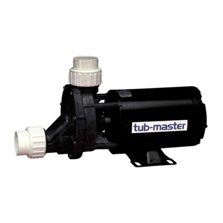
Aqua Flo "A" Series & "LEA" Series Pumps A Series User manual

OWNER’S MANUAL
“A” SERIES & “LEA” SERIES PUMPS
IMPORTANT SAFETY INSTRUCTIONS
When installing and using this electrical equipment, basic
safety precautions should always be followed, including the
following:
1. READ AND FOLLOW ALL
INSTRUCTIONS.
2. WARNING : To reduce the risk of injury, do not permit
children to use this product unless they are closely
supervised at all times.
3. CAUTION: This pump is for use with permanently
installed pools and may also be used with hot tubs and spas
if so marked. Do not use with storable pools. A permanently
installed pool is constructed in or on the ground or in a
building such that it cannot be readily disassembled for
storage. A storable pool is constructed so that it may be
readily disassembled for storage and reassembled to its
original integrity and has a maximum dimension of 18 ft.
(5.49m) and a maximum wall height of 42 in. (1.07m).
4. Do not install within an outer enclosure or beneath the
skirt of a hot tub or spa unless so marked.
5. SAVE THESE INSTRUCTIONS.
05/04 1 97490010

INSTALLATION & OPERATING INSTRUCTIONS
GENERAL
Your AQUA-FLO pump has been quality built and engineered to give maximum
efficiency under normal water pumping conditions. Consult the manufacturer for
any other applications.
LOCATION OF PUMP
For best pump performance, locate the system as close to the water source as
possible. Provide adequate access around the pump for inspection and
maintenance. Place pump on a firm level surface. Pump need not be bolted
down unless required by local code.
PUMP CONNECTIONS
Suction line from pool (skimmer and main drain) must be connected to inlet at
hair and lint trap. Discharge line to pool (return lines) must be connected to
outlet at top of pump via filter. If pump is installed below water level of pool,
install valves on the inlet and outlet piping to permit removing of equipment
without draining the pool.
CAUTION: During the pressure test procedure, this pump is under pressure.
DO NOT LOOSEN lock handles while pump is running or until all pressure is
released. Tighten lock handles securely by hand only. Raise pressure slowly.
Do not exceed 50 psi. Extreme care must be taken during pressure test. Failure
to follow these instructions explicitly can result in personal injury.
PRIMING PUMP
At initial start-up, pump must be primed by filling hair and lint trap with water. To
prime pump, remove cover from hair and lint trap: fill pump and suction trap with
water. Replace cover (make sure the o-ring is in place) and tighten lock handles.
Pump will now prime, with priming time depending upon lift and horizontal
distance of suction piping.
CAUTION:Do not remove hair and lint strainer lid while pump is running or
under pressure! Lid is held in place by lock handles which can be removed or
tightened by hand. Basket must be kept clear of leaves and debris at all times.
REMOVING BASKET
1.) Turn off motor. 2.) Remove lid. 3.) Remove basket and empty debris. 4.)
Replace basket, fill with water, replace lid securely to prevent air from
entering and tighten. DO NOT USE TOOLS. 5.) Turn on motor. 6.) Open
air-relief valve on top of filter until steady stream of water comes out.
NOTE: If pump is installed below water level of pool, close return and suction
lines prior to opening hair and lint pot. Make sure to re-open valves prior to
operating.
DO NOT RUN PUMP DRY!
Always maintain proper water level in pool. If water level falls below skimmer
intake, pump will suck air. Pump is equipped with a maintenance-free, heavy-
duty mechanical seal. Damage will occur if pump runs dry, and warranty will be
voided.
TO PREVENT FREEZING
Drain liquid from pump through plug at bottom section of volute. It is
recommended to apply a good rust inhibitor into liquid end to prevent corrosion.
2

Be sure motor is kept dry and covered. In mild climate area, when freezing may
occur, run pump and filter equipment continuously to prevent freezing.
MOTOR
Your pump is equipped with a permanently lubricated, maintenance-free, heavy-
duty industrial quality motor especially designed to withstand the heavy-duty
requirements of swimming pool application. Wiring connection must agree with
incoming line voltage. Improper wiring can cause serious injuries and damage to
the motor, voiding warranty.
NOTE: Your motor is designed to withstand the effects of normal rainfall. To
increase the life of your motor, observe the following:
1.) Do not flood motor or submerge in water. To do so voids warranty.
2.) Provide ample cross ventilation, minimum of 6” at all points.
3.) Keep motor and surrounding area clean.
4.) Avoid sweeping or stirring dust near motor while it is running.
5.) Avoid storing or spilling dry chemicals, powders, etc., near motor.
6.) Provide protection against the elements.
7.) Locate motor on a slight elevation so water will drain away from motor.
8.) Avoid spilling or dripping liquid chemical on or near motor.
9.) Avoid splashing water or hosing deck near motor. Water damage voids
warranty.
For replacements, contact your local supplier or authorized service center.
WARNING - All electrical wiring of the motor installation must be done by a
qualified electrician in accordance with applicable electrical codes. Before
working on any motor, be certain that the source of electrical power is off
at the main junction box.
BONDING WIRE - Upon installation of the pump, the motor must be bonded
with (no smaller than) a No. 8 AWG solid copper conductor per National
Electrical Code. The connection should be from the accessible wire
connector on the motor to all metal parts of the swimming pool, spa or hot
tub structure and to all electrical equipment, metal conduit, and metal
piping within 6 feet (1.5 m) of the inside walls of a swimming pool, spa or
hot tub, when the motor is installed within 5 feet of the inside walls of the
swimming pool, spa, or hot tub.
NOTE: For electrical connections, see wiring diagram on motor rating
plate.
3

TROUBLE SHOOTING
PROBLEM SOLUTION
Hair and lint pot cover is tight and o-ring is in place
and free from defects.
Valves on suction and return lines are working
properly and open.
Water level in pool is too low.
Filter o-ring or gasket is in place and free from
defects.
If pump loses prime,
or if too many bubbles
come through return
line, check:
All fittings and connections are secure and air tight.
Filter pressure gauge reading too high, indicating filter
needs cleaning.
Clogged plumbing lines.
Impeller adjustment incorrect. Adjust impeller .015
inches from face of volute.
Not pumping water,
check:
Worn or damaged impeller.
Circuit breakers.
Incorrect or loose wire connections.
Motor does not run,
check:
Thermal protector in motor tripped. Allow motor to
cool, then try to restart.
Make sure motor shaft turns free.
Jammed impeller or an obstruction in (volute) casing.
Motor makes
humming noise but
won’t start, check: Low voltage and undersized wire.
Incorrect or loose wire connections.
Low voltage supply (frequently caused by undersized
wire.
Motor overheating and
cycling on and off,
check:
Make sure the motor gets a fresh air supply and the
vents are kept unclogged.
Plumbing vibration
Impeller turns freely and is properly adjusted.
Motor bearings.
Noises, check:
For cavitation, due to obstruction in or undersized
suction line.
4

ASSEMBLY INSTRUCTIONS FOR MOUNTING
LIQUID END TO MOTOR
STEP 1
Remove pump and motor from their boxes and check for any possible shipping
damage.
STEP 2
Place motor vertically with shaft end up, being careful not to damage motor end
bell. Remove shaft key on motor if installed.
STEP 3
Install liquid end to motor by placing the pump shaft onto the motor shaft and
aligning the pump shaft set screws with the motor shaft keyway. Align pump
bracket holes with threaded holes on motor and install four 3/8”-16 hexbolts and
tighten with 9/16” wrench.
STEP 4
Place assembled pump in its normal position, on the pump base. To adjust
impeller, place screwdriver on the pump shaft as shown, and gently pry pump
shaft towards motor .015 inches and tighten one set screw with 1/8” Allen
wrench. Rotate shaft to check if impeller is clear. If impeller is clear, tighten all
set screws firmly. If impeller is not clear, loosen set screw and adjust impeller
further until it rotates freely.
(See illustration above)
STEP 5
The pump is now ready for installation.
5

"A" SERIES REPLACEMENT PARTS
Please refer to diagram located on page 7
Ref.
No.
Part No. Description
1 Motor, 56 Frame, 'C' Face, Keyed Shaft
2 9252000220002 Shaft, Extension, Solid EndShaft, Extension, Solid End
33 9973000099730000 Screw, Socket Set, 1/4"-20 x 5/16"Screw, Socket Set, 1/4"-20 x 5/16"
44 9114005091140050 Bracket, .33-2.0 HPBracket, .33-2.0 HP
44 9114010091140100 Bracket, .33-2.0 HP, With FootBracket, .33-2.0 HP, With Foot
44 9114015091140150 Bracket, 3.0 HPBracket, 3.0 HP
55 9905003099050030 Bolt, Hex Machine, 5/16"-18 x 5/8"Bolt, Hex Machine, 5/16"-18 x 5/8"
66 9905005099050050 Bolt, Hex Machine, 3/8"-16 x 5/8"Bolt, Hex Machine, 3/8"-16 x 5/8"
77 9150005091500050 Gasket, Volute, .33-2.0HPGasket, Volute, .33-2.0HP
77 9150010091500100 Gasket, Volute, 3.0HPGasket, Volute, 3.0HP
88 9250005092500050 Seal, Replacement, #1000Seal, Replacement, #1000
99 9169100091691000 Impeller, .33 HPImpeller, .33 HP
99 9169105091691050 Impeller, .50 HPImpeller, .50 HP
99 9169110191691101 Impeller, .75 HPImpeller, .75 HP
99 9169115191691151 Impeller, 1.0 HPImpeller, 1.0 HP
99 9169120191691201 Impeller, 1.5 HPImpeller, 1.5 HP
99 9169125191691251 Impeller, 2.0 HPImpeller, 2.0 HP
99 9169130091691300 Impeller, 3.0 HPImpeller, 3.0 HP
1010 9277005092770050 Volute, .33-2.0 HP, 1-1/2" Discharge, With FootVolute, .33-2.0 HP, 1-1/2" Discharge, With Foot
1010 9277006092770060 Volute, .33-2.0 HP, 1-1/2" Discharge, Less FootVolute, .33-2.0 HP, 1-1/2" Discharge, Less Foot
1010 9277015092770150 Volute, 3.0 HPVolute, 3.0 HP
10A†
10A 92770200†
92770200 Volute, .33-2.0 HP, 100% Drain †
1111 9110010091100100 Base, PlasticBase, Plastic
1212 9905011099050110 Bolt, Hex, Machine, 5/16"-18 x 1"Bolt, Hex, Machine, 5/16"-18 x 1"
1313 9989005099890050 Washer, Lock 5/16"Washer, Lock 5/16"
1414 9229000092290000 Plug, PipePlug, Pipe
1515 9150015091500150 Gasket, Trap, 5"Gasket, Trap, 5"
1515 9150020091500200 Gasket, Trap, 6" & 8"Gasket, Trap, 6" & 8"
1616 9262000092620000 Trap, 5", 1-1/2" SuctionTrap, 5", 1-1/2" Suction
1616 9262005092620050 Trap, 5", 2" SuctionTrap, 5", 2" Suction
1616 9262010092620100 Trap, 6", 2" SuctionTrap, 6", 2" Suction
1717 9111000091110000 Basket, Strainer, 5" (plastic)Basket, Strainer, 5" (plastic)
1717 9111001091110010 Basket, Strainer, 6" (plastic)Basket, Strainer, 6" (plastic)
1818 9220000092200000 O'ring, Trap Cover, 5", #429O'ring, Trap Cover, 5", #429
1818 9220001092200010 O'ring, Trap Cover, 6", #438O'ring, Trap Cover, 6", #438
1919 9123000091230000 Cover, Trap, 5"Cover, Trap, 5"
1919 9123005091230050 Cover, Trap, 6"Cover, Trap, 6"
2020 9192000191920001 LockhandleLockhandle
2121 9150025091500250 Gasket, 100% DrainGasket, 100% Drain
22†
22 56910030†
56910030 Flange, 100% Drain †
2323 9973005099730050 Screw, #8-32 x 5/8"Screw, #8-32 x 5/8"
QQ 9104001091040010 Assembly, Trap Complete, 5" x 1-1/2"Assembly, Trap Complete, 5" x 1-1/2"
QQ 9104002091040020 Assembly, Trap Complete, 5" x 2"Assembly, Trap Complete, 5" x 2"
QQ 9104003091040030 Assembly, Trap Complete, 6" x 2"Assembly, Trap Complete, 6" x 2"
† No longer available† No longer available
† †Volute, .33-2.0 HP, 100% Drain †
† † Flange, 100% Drain †
Q Trap Assembly includes Ref. No.'s 5, 14-20
6

DIAGRAM – Please Refer to table located on page 6
AQUA-FLO, LLC
P.O. BOX 2526 • CHINO, CALIFORNIA 91708
SHIPPING: 5651 SCHAEFER AVENUE • CHINO, CALIFORNIA 91710
TEL 909/591-7453 • FAX 909/627-5660
WWW.AQUA-FLO.COM
7

“A” SERIES & “LEA” SERIES PUMPS LIMITED WARRANTY
AQUA-FLO, LLC
WARRANTS TO:
the original retail purchaser only, that the products Aqua-Flo manufactures are
free from defects in material and/or workmanship for a period of five years from
date of purchase, not to exceed six years from date of manufacture, (pump seals
warranty for 30 days). If within the first two years from date of manufacture, any
such product proves to be defective, it shall be repaired or replaced at AQUA-
FLO’S option as follows:
The original retail purchaser shall first contact the installing dealer, as soon as
possible after discovery of the defect, but in no event later that the expiration
date of this warranty. Or upon notification,
AQUA-FLO, LLC
Customer Service Department
P.O. Box 2526, Chino, CA 91708
will advise the consumer of the address to which the defective item may be
shipped, together with the model number, serial number and date of purchase of
item claimed to be defective. The consumer must pay for all shipping charges.
If within the years three through five any such products shall prove defective, the
original retail purchaser shall be entitled to purchase replacement equipment or
components at the following percentage off the current published list price:
Third year 60%
Fourth year 40%
Fifth year 20%
1. This warranty shall not apply to any failures resulting from negligence, abuse,
misuse, misapplication, improper installation, alteration or modification,
chemical corrosion, or improper maintenance.
2. Any items manufactured by other companies and used by AQUA-FLO in its
products may carry warranties by the original manufacturers.
3. AQUA-FLO is not liable for incidental or consequential damages, loss of time,
inconvenience, incidental expenses, labor or material charges in connection
with removal or replacement of the equipment.
AQUA-FLO is not responsible for any implied warranties or representations by
others, and the foregoing warranty is exclusive and in lieu of all warranties
provided herein.
Some states do not allow the exclusion or limitation of incidental or consequential
damages, so the above limitation or exclusion may not apply to you.
This warranty gives you specific legal rights, and you may also have other rights
which vary from state to state.
8
This manual suits for next models
2
Table of contents
Other Aqua Flo Water Pump manuals
Popular Water Pump manuals by other brands

Lilie
Lilie Shurflo 8000 Series Installation and operation manual

WELCH-ILMVAC
WELCH-ILMVAC 2585B-01 owner's manual

Uponor
Uponor Pumpgroup Push-12-AC Mounting instructions

Mallory
Mallory COMP PUMP 5110FI installation instructions

RUNZEL
RUNZEL LM60A instruction manual

Water Powered Technologies
Water Powered Technologies Papa Pump owner's manual

Pentair
Pentair FAIRBANKS NIJHUIS 5430 Installation, operation and maintenance manual

STRANGKO
STRANGKO 3106 700 user manual

Pentair
Pentair ONGA VF150 owner's manual

Xylem
Xylem Goulds CentriPro Series Service manual

Wilden
Wilden Advanced Series Engineering, operation & maintenance

Metabo
Metabo HWA 6000 Inox manual