Aquacal HP9 User guide

AquaCal®
APPLICATION BULLETIN
#0005
CONNECTING AND USING A JANDY VARIABLE SPEED CIRCULATION PUMP
REQUIRED FIRMWARE - EQUIPMENT
Heat Pump with an HP9 Control Board
Firmware Version 2.000 or higher
AB0005 REL 1- (project rel 8.00)

Page - 1
1 - Connecting the Jandy Circulation Pump to the Heat Pump
PLEASE NOTE
This bulletin is not meant to be all inclusive and work for every Jandy variable speed
circulation pump. This bulletin does cover the majority of Jandy Variable Speed Circulation
pumps.
What is Required
1. Heat Pump with an HP9 Control Board. See Figure 1.
2. Heat Pump firmware with a revision number of 2.000 or higher. See Figure 2.
lIf unsure about firmware version, see "Viewing System Information" on page8.
lThe firmware can be upgraded if necessary. Check with an AquaCal Customer Support representative for a
USB firmware upgrade drive if needed.
3. At least one equipment group needs to exist in order to use a circulation pump. If an equipment group does not
exist, see document #LTP0167 (Expansion Board Upgrade Manual) for information on creating groups.
4. A two-conductor wire (shielded 300V, twisted pair) of sufficient length to run from the circulation pump to the
heat pump. Confirm with circulation pump manufacturer manual for size and type of wire.
Figure 1 - HP9 Control Board
Figure 2 - Firmware Version
Wiring
DANGER Failure to heed the following will result in injury or death.
lDeactivate power while routing wiring to control board.
lRISK OF ELECTRICAL SHOCK FROM ENERGY STORED IN CAPACITORS - MODELS EQUIPPED
WITH VARIABLE FREQUENCY COMPRESSOR DRIVES STORE ELECTRICITY EVEN AFTER THE
POWER HAS BEEN DEACTIVATED AT THE POWER BREAKER. Wait for 2 minutes after the shut down
of equipment before servicing.
lFollow all National Electric Codes (NEC) and/or State and Local guidelines.
WARNING Failure to heed the following may result in injury or death.
lInstallation of this equipment by anyone other than a qualified installer can result in a safety hazard.
lThe information contained throughout the "Installation" section is intended for use by qualified installation
technicians familiar with the swimming Pool/Spa safety standards.

Page - 2
Figure 3 - Circulation Pump
1. Turn off power to heat pump and circulation pump at breaker
panel.
Figure 4 - Top Access Cover
2. Remove circulation pump top access cover. See Figure 4.
3. Remove inner wire cover. See Figure 5 and Figure 6.
Figure 5 - Inner Wire Cover Removal Figure 6 - Inner Wire Cover Removed

Page - 3
Figure 7 - Wires from Circulation Pump to
Heat Pump
4. Connect wire to run to the heat pump from connection points
"2" and "3". The first (power) wire and fourth (ground) wire
will not be used. See Figure 7.
lRun wires to the heat pump through the circulation pump
chassis per circulation pump recommendations.
lBe sure to secure the wires running to the heat pump so
they aren't a tripping hazard.
Figure 8 - DIP switches
5. Set DIP switches on circulation pump for variable speed
control and to set address. See Figure 8.
lCheck circulation pump manual for specifics. As of this
writing, DIP switch settings are as follows:
JANDY DIP SWITCH CHART
Port Address Switch 1 Switch 2 Switch 3 Switch 4
1ON ON OFF OFF
2ON ON ON OFF
3ON ON OFF ON
4ON ON ON ON
6. Follow pump manufacturer recommendations for routing wiring out of the circulation pump.

Page - 4
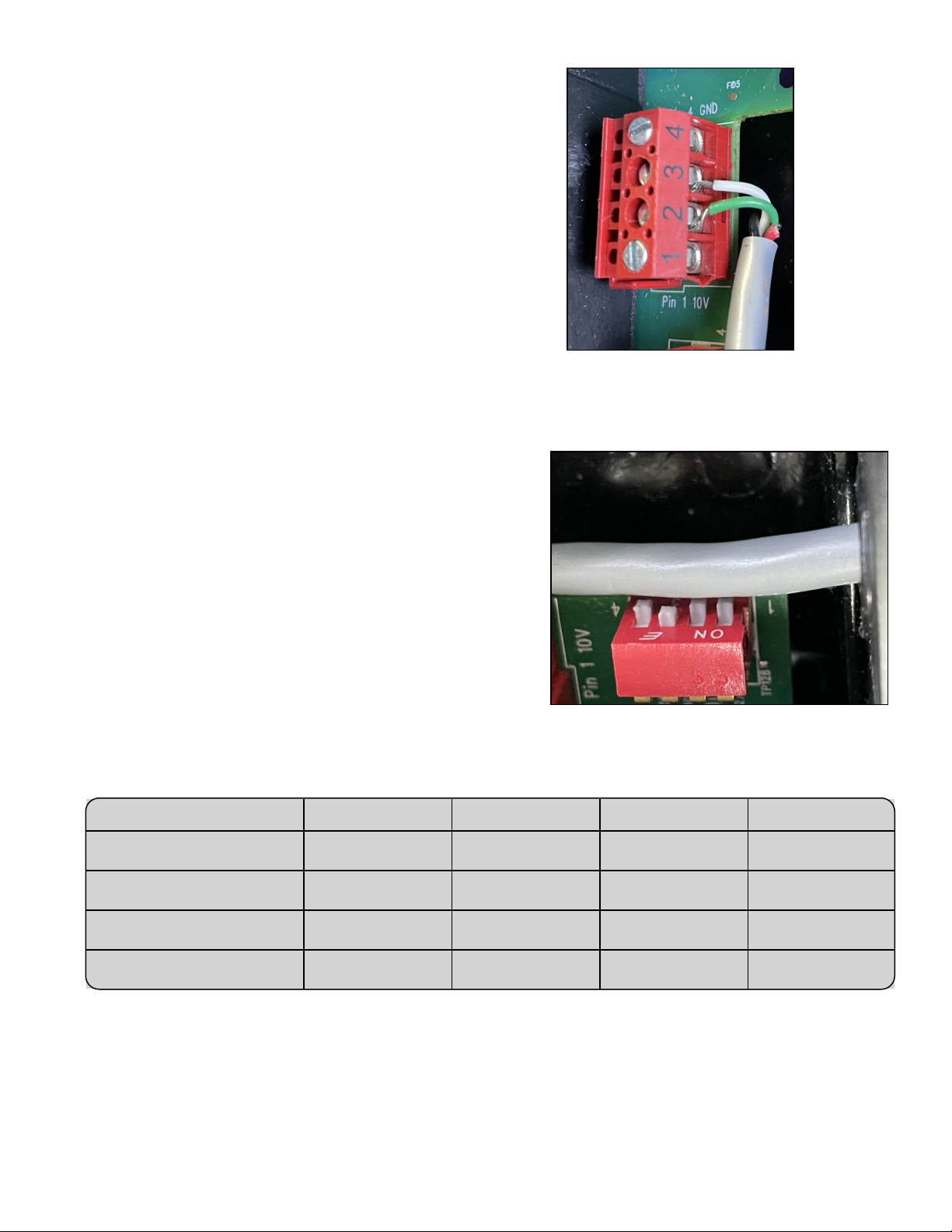
Figure 9 - Wires to Port "B" on HP9
7. Remove the heat pump's access panels.
8. Route the wires from the circulation pump
to the heat pump's electrical enclosure.
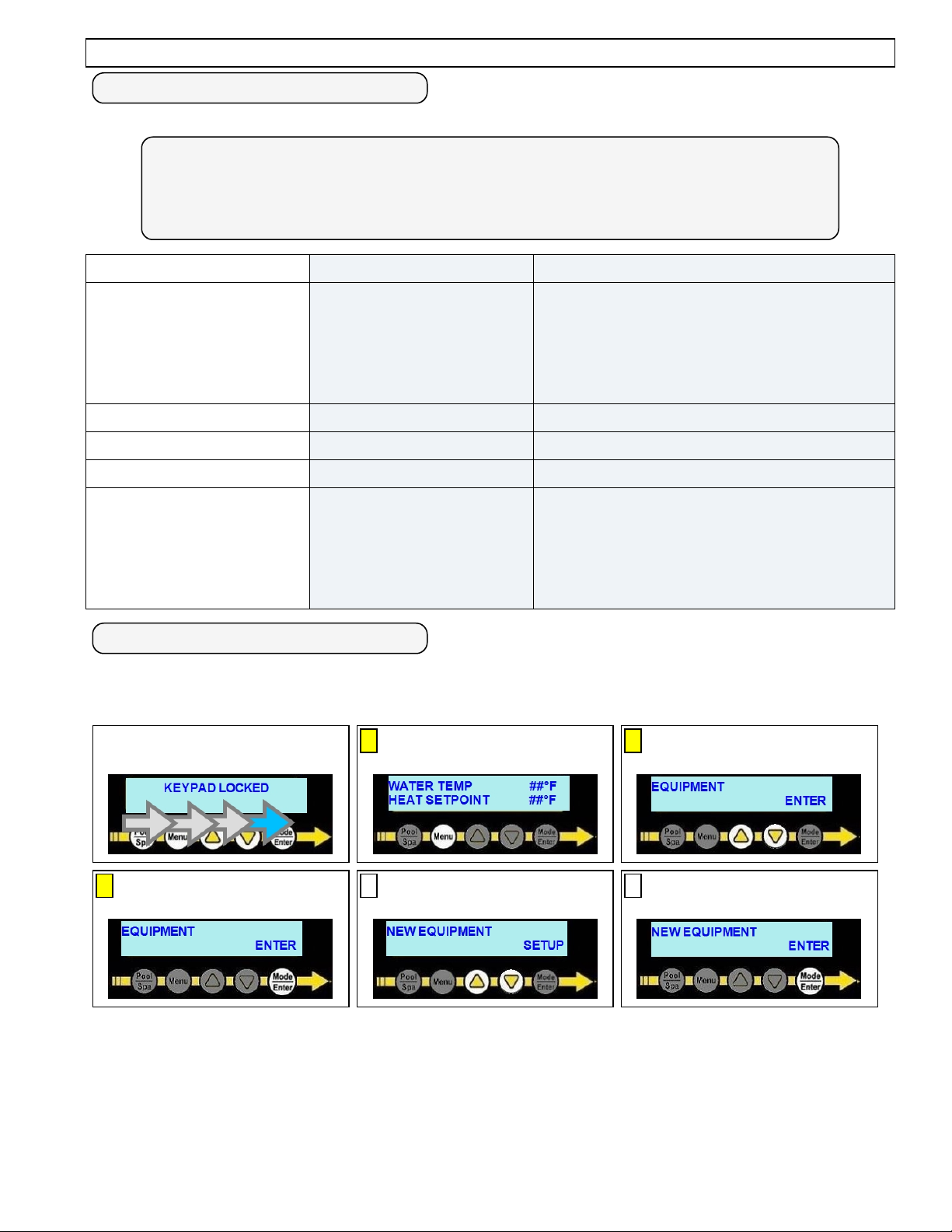
Figure 10 - Removing Blue
Connector From Port "B"
9. Connect the wire to the heat pump's control board (RS-485 Port "B") as
specified below. See Figure 9.
lThe blue connectors can be removed for ease in wiring and to properly
identify the correct port. See Figure 10.
lConnect the circulation pump wire "2" to the heat pump's "B" connection
point (Port "B").
lConnect the circulation pump wire "3" to the heat pump's "Y" connection
point (Port "B").
10. Turn on power to heat pump and circulation pump.
11. Configure heat pump to use circulation pump. See "Manually Configuring
the Heat Pump to use the Circulation Pump" on the facing page.
12. Confirm the heat pump is communicating with the circulation pump. No faults should display on the heat pump.
If the heat pump displays "CIRCULATION PUMP FAULT", then communication to the circulation pump
failed.
i. Confirm both devices are receiving power.
ii. Confirm circulation pump address is correctly entered in the heat pump's configuration.
iii. If fault continues to occur, turn off power to heat pump and circulation pump at breaker panel.
iv. Wait two (2) minutes for power to discharge from heat pump's capacitors.
v. Reverse the wires connected to the "B" and "Y" leads on the heat pump.
vi. Turn on power to both devices and confirm no faults occur.
vii. If a fault continues to occur, power off equipment and wait two (2) minutes. Then use a ground wire with a
100 ohm resistor at both ends of the wire. Run the wire from the heat pump's port C ("G") connection to the
circulation pump's ("COM") connection. Follow recommended RS-485 communication standards regarding
ground insertion resistors.
viii. Turn on power to both devices and confirm no faults occur. If a fault continues to occur, contact technical
support.
13. Turn off power to heat pump and circulation pump at breaker panel.
14. Wait two (2) minutes for power to discharge from heat pump's capacitors.
15. Replace access panels on heat pump and circulation pump.

Page - 5
2 - Manually Configuring the Heat Pump to use the Circulation Pump
Circulation Pump Settings Chart
Use this chart when entering parameters in the configuration.
PLEASE NOTE
Some circulation pumps will not allow for an address other than address "1". Review
circulation pump documentation for capabilities of changing circulation pump addresses
(and dip switches) if needed.
To Configure: Parameter Usage
ENTER HERE Port Address To Use
Multiple circulation pumps can be controlled by
the heat pump. Each pump is required to have
its own address. Available ports are 1,2,3, and
4 for a variable speed circulation pump. The
default is usually address "1".
ENTER HERE Minimum Allowed RPM As stated in the circulation pump manual.
ENTER HERE Maximum Allowed RPM As stated in the circulation pump manual.
ENTER HERE Priming Speed RPM As stated in the circulation pump manual.
ENTER HERE Heat / Cool Speed RPM
This is the required RPM for the heat pump to
operate properly when actively heating or
cooling the water. Make sure not to exceed the
RPM requirements of the circulation system
and heat pump.
Configuration at the Heat Pump
At this point, the only things being entered are the capabilities of the circulation pump and heat pump. The
user will be given a chance to set preferred RPMs (Revolutions per minute) in group settings.
IF UNIT IS ASLEEP,
SWIPE TO WAKE UP
APRESS MENU
BUTTON
BUSE ARROWS TO
"EQUIPMENT"
CPRESS "ENTER" 1USE ARROWS TO MENU
"NEW EQUIPMENT"
2ENTER TO SELECT

Page - 6
3USE ARROWS TO
"PUMP"
4ENTER TO SELECT 5USE ARROWS TO MENU
DEVICE NAME
6ENTER TO SAVE 7USE ARROWS TO
SELECT PUMP TYPE
8ENTER TO SAVE
9USE ARROWS TO
SELECT DEVICE'S PORT
10 ENTER TO SELECT 11 USE ARROWS TO SET
MINIMUM RPM SPEED
12 ENTER TO SAVE 13 USE ARROWS TO SET
MAXIMUM RPM SPEED
14 ENTER TO SAVE
15 USE ARROWS TO SET
PRIMING TIME
16 ENTER TO SAVE 17 USE ARROWS TO SET
PRIMING SPEED
18 ENTER TO SAVE 19 USE ARROWS TO SET
HEAT / COOL SPEED
20 ENTER TO SAVE
21 PRESS BUTTON UNDER
"YES" TO SAVE SETUP
MENU TO EXIT, PRESS
& HOLD TO STATUS
The configured device will now be available for insertion into a group.

Page - 7
3 - Add the Circulation Pump to a Group
The example below shows the "POOL" group being edited to add a variable speed
circulation pump.
If a group does not exist, see document # LTP0167 (Expansion Board Upgrade Manual) for
information on creating groups.
PLEASE NOTE
The user will be prompted for the variable speed circulation pump's operating RPMs
(Revolutions per minute) within the group.
lThe RPM speed is set after the circulation pump has finished it's priming operation
(configured in the equipment setup).
lThis will be the regular operating speed of the circulation pump when the heat pump's
compressor is off and not actively heating or cooling the water. Code-specified whole system
turnover rates must be satisfied.
IF UNIT IS ASLEEP,
SWIPE TO WAKE UP
APRESS "MENU"
BUTTON
BUSE ARROWS TO
"GROUPS"
CPRESS "ENTER" 1USE ARROWS TO
GROUP TO EDIT
2ENTER TO EDIT
3USE ARROWS TO
"ADD EQUIPMENT"
4ENTER TO SELECT 5USE ARROWS TO
CHOOSE EQUIPMENT
6ENTER TO SELECT 7USE ARROWS TO SET
PUMP'S RPM
8ENTER TO SAVE
MENU TO EXIT, PRESS
& HOLD TO STATUS
The configured group is ready to be used by
either pressing the "POOL/ SPA" button,
or setting a schedule.

Page - 8
4 - Appendix
4.1 Viewing System Information
The heat pump model, serial number, and firmware version can be viewed in the
information menus.
IF UNIT IS ASLEEP,
SWIPE TO WAKE UP
APRESS MENU
BUTTON
BUSE ARROWS TO
"SYSTEM"
CPRESS "ENTER" 1USE ARROWS TO MENU
"INFORMATION"
2PRESS ENTER TO VIEW
3USE ARROWS TO VIEW
"UNIT SERIAL NUMBER"
4USE ARROWS TO VIEW
"UNIT MODEL NUMBER"
5USE ARROWS TO VIEW
"FIRMWARE VERSION"
MENU TO EXIT, PRESS
& HOLD TO STATUS
Other manuals for HP9
1
Table of contents