AQUASTRONG AQUA Series User manual


1
2
2
3
4
6
7
8
9
Contents
1.Foreword
10
2.Product Overview
3.Model
4.Product Structure
5.Warnings
6.Pipeline Installation
7.Electrical Connection
8.Start-up & Maintenance
9.Common Troubleshooting
10.Maintenance Diagram

1. Foreword
1
Please read carefully this Specification before using the product.
The manufacturer will not assume any responsibility for any malfunction or loss caused by
failure to comply with the precautions specified in the Specification. Please keep all the
documents in good condition. If you have any questions, please call us or contact the
local dealer.
The Specification details the installation, use and maintenance of the electric pump and
provides important safety information. For the safety of you and others, we kindly request
that you read this Specification carefully and strictly follow its recommendations to install,
use and maintain the products you purchase. We would like to take thisopportunity to
thank you for your choice. Your satisfaction is our greatest success!
If you have any valuable comments, please call the customer service hotline or write to us.
We will deliberate on your comment and reply in time whether we抣l adopt it or not.
Thank you for your support!
Note:
All information, illustrations and specifications herein are subject to the latest product
information obtained at the time of publication.
As the product is constantly updated, if the nameplate parameters are found to differ from
this Specification, the nameplate shall prevail.

2
2. Product Overview
3. Model
AQUA series high-pressure self-priming pump is a compact water supply system suitable for home water
intake, well water lifting, pipeline pressurization, garden watering, vegetable greenhouse watering and
aquaculture. It is also suitable for water supply and drainage in rivers, wells, rural areas, hotels, canteens
and high-rise buildings. The power supply frequency is 50Hz, the single-phase voltage is 160-260v, and
the three-phase voltage is 380v; see the product nameplate.
Note: The s ingle-phase high-pressure self-priming pump is divided into automatic pump and
non-automatic pump. All non-automatic pumps can be converted to automatic pumps. The automatic
pump is made up of a non-automatic pump that is added an automatic device which consists of a
pressure switch and a pressure tank. The function features: when the power is on and the faucet is
opened, the pump will work automatically, and vice versa. If it is used with a water tower, through the
connection with an upper limit switch, it can automatically work or stop based on the water level in the
water tower.
PH Value: 6-8.5
Ambient Temperature: 0-40 degrees
Liquid Temperature: 0-100 degrees
Relative Humidity: Max. 85% (RH)
Inlet Pressure: Must be lower than the start value of the pressure switch
160-260V/50Hz
160-260V/60Hz
220-240V/50Hz
100-120V/60Hz
AQUA25
AQUA30
AQUA35
AQUA45
AQUA50
Model
Voltage/
Frequency
(V/HZ)
Max.Flow
(m3/h)
Rated Flow
(m3/h)
Output Power
(w)
Max.Head
(m)
Rated Head
(m)
250
370
450
750
850
1.8
2.5
2.5
3
3.5
25
30
35
45
50
1
1.3
1.5
1.5
1.5
12
13.5
15
22
28

3
4. Product Structure
1
2
3
4
5
6
7
8
Flow sensor
Inlet flange
Check valve carrier
Pressure tank
Pump
Impeller
Mechanical seal
O-ring
Bracket
Bearing
Rotor and stator
12
9
10
11
Circuit cuit board
components
13
14
15
Capacitor
Fan
Fan cover
AQUA25

4
1
2
3
4
5
6
7
8
9
10
Flow sensor
Inlet flange
Check valve carrier
Water fill in plug
Pressure switch
Pressure tank
Pump
Impeller
Mechanical seal
O-ring
11
12
13
14
16
17
18
19
Bracket
Rotor
Bearing
Stator
Capacitor
Circuit board
Fan
Fan cover
15 Circuit cuit board
components
5. Warnings
Please follow the Specification strictly when using the product.
Before connecting to power, please check the insulation resistance carefully to
prevent electric leakage.
The pump should be grounded reliably and equipped with a leakage protection
switch.
Do not touch the product after it is powered on. Do not wash, swim or put live
stock in water in the vicinity to avoid electric shock.
The pump must be first powered o ffbefore repairs in case of any malfunction.
1. The power must be turned o ffbefore installation and maintenance. The
pump should be grounded reliably. To prevent electric shock, be sure to install
a leakage protection switch. If there is moisture on the plug, it will cause electric
shock. Please be careful.
AQUA30 / AQUA35 / AQUA45 / AQUA50

5
2. Do not use any liquid other than water. When using readily soluble substances
like benzoic acid, flammable materials like gasoline and viscous bottleneck liquids,
it is easy to cause a fire.
4. Avoid operation in a waterless state, for it will shorten the service life of the
pump. When the motor is overheated, it is easy to have malfunctions. Do not
expose the pump to direct light during operation, for it will affect the service life
of the pump. The automatic pumps will enter the water shortage protection
system to protect the pump, so when the user uses the pump for a second time,
he only needs to re-plug the plugto use normally (the tap will open automatically).
3. During operation, it is strictly prohibited to touch the pump. Do not wash,
swim or put livestock in water in the vicinity of the work area in case of accidents.
If abnormalities are found during operation, such as abnormal noise, less water
outlet and intermittent water flow, the power should be cut o ffimmediately
to check and eliminate the fault. When the pump is wet, do not touch the pump
when it is powered on in case of accidents. Avoid splashing water on the pump
and prevent thepump from immersing in water.
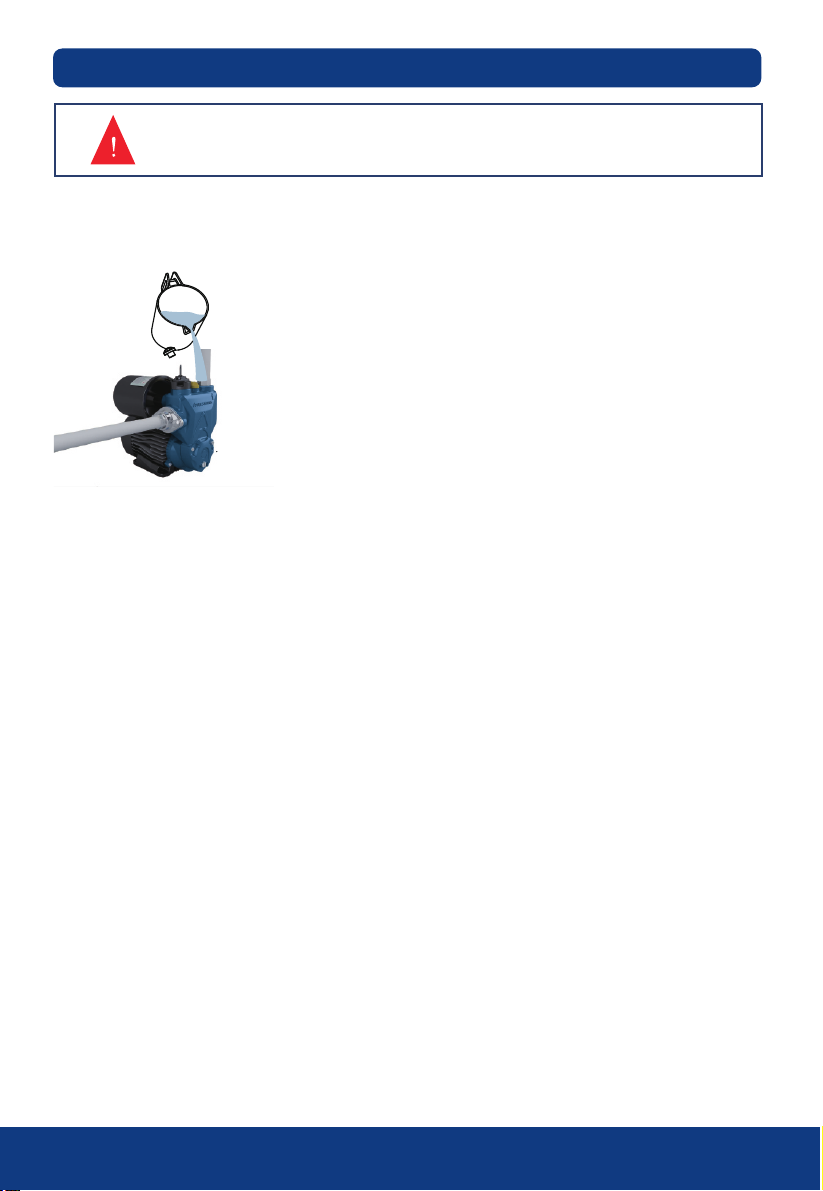
5. Before starting, first move the fan blade to check whether the pump can
operate flexibly; then unscrew the water injection plug, fill the pump with clean
water from the water injection hole, then tighten the water injection plug after
the air is exhausted.
Keep the valve almost closed at startup; when there is water discharged, adjust
the valve to have the required flow.
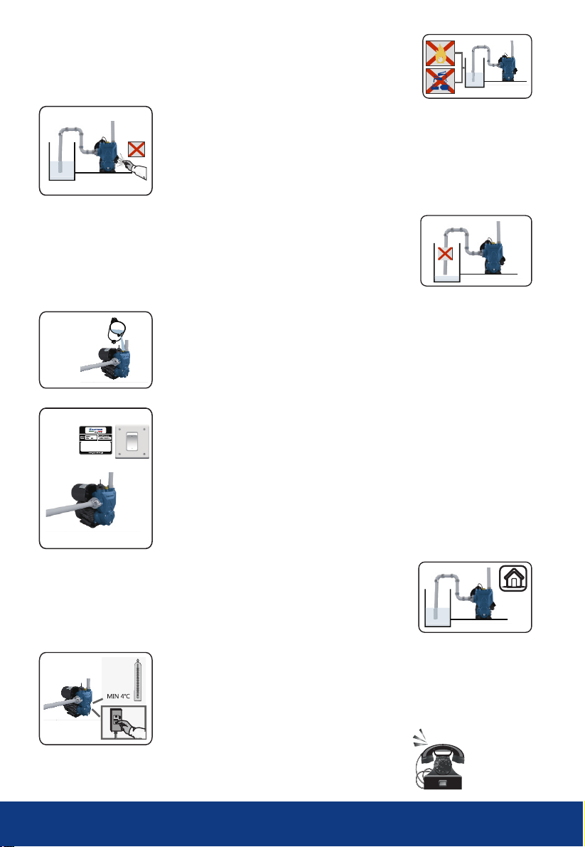
8-1. When the ambient temperature is lower than 4¥, please take antifreeze
measures to prevent the pump from frost crack;
8-2. Keep ventilation
7. If the pump is installed indoors, a drainage system must be arranged near
the pump.
Prevent the pump from immersing in water, for it may cause the motor to burn
out or electric shock. If the pump is not installed as required,which results in the
user抯 property and safety loss, the company will not bear the responsibility.
9. If you have any questions, please refer to the Specification or contact us.
6-1. During installation and maintenance, ensure that the pump won抰 be
accidentally powered on. If it is not used for a long time, close the pipe valves
at the water inlet and outlet, and pay attention to cut o ffthe power first.
6-2. The pumped liquid may be hot and under high pressure. Before moving
and disassembling the pump, the valves must be closed before draining the
pump and the pipe to avoid burns.
6-3. Supply power according to the voltage indicated on the nameplate. If the
pump is not used for a long time, it should be stored in a dry, ventilated and
cool place at room temperature.
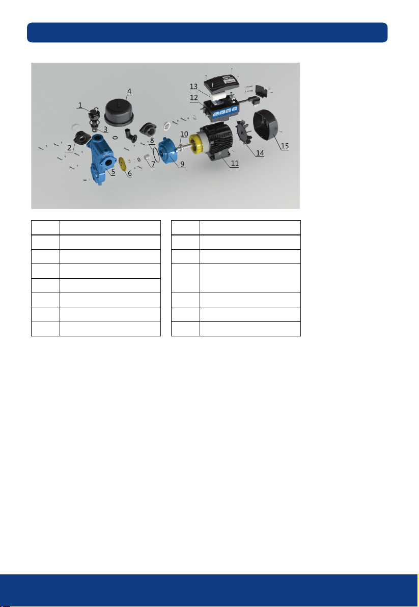
water injection
Max.Head: 25m
Max.Capacity: 1.8m /h
Inlet&Outlet Dia: 25mm
C 10 μF VL 450 V
RPM: 2860r/min
Max.Suction: 8m
l CL B IPX4
Continuous duty
3
Thermally Protected
S.NR: A18090001

& M
07 Start-up aintenance
6
6. Pipeline Installation
Correct Installation Diagram A
Wrong Installation Diagram B
1. Drain plug
2. Electric pump
3. Outlet pipe
4. Water injection plug
B: Precautions for water inlet installation:
The inlet diameter should be at least thesame as the
outlet diameter, so that its pressure drop, high flow
and noise can be minimized.
A: Precautions for installation of water inlet pipe
1. When installing the pump, it is forbidden to use soft rubber hose in the water inlet pipe to avoid deviated
suction;
2. Install the bottom valve vertically and 30cm away from the bottom, so as not to absorb the sediment.
3. Each joint of the inlet pipe must be sealed; try to reduce the number of elbows, or it won抰 be able to
absorb water.
4. The diameter of the inlet pipe should be at least similar to the diameter of the water inlet to prevent
excessive water loss and affecting the performance of water discharge.
5. During operation, pay attention to the water level drop, the bottom valve should not be exposed to the
water surface.
6. The length of the water inlet pipe is greater than 10m, or when the inlet pipe lifting height is greater
than 4m, the inlet pipe diameter shall be greater than the diameter of
the water inlet.
7. When installing the pipeline, ensure that the pump will not be subjected to the pipeline.
8. In case of special circumstances, the pump series are allowed to not install the bottom valve, however,
in order to prevent particles from entering the pump, the inlet pipe must be installed a filter.
5. Water inlet
6. Elbow
7. Inlet pipe
8. Bottom valve

7
Electrical connection and protection shall comply with the local regulations.
The operating voltage is marked on the nameplate, please ensure that the motor matches the power
supply. If the pump operation area is far away from the power supply, the power cord should be properly
thickened, otherwise, the great voltage drop will affect the normal operation of the pump. If the pump is
used outdoors, the extension cord must use a special rubber cable dedicated for outdoor use.
Check the motor rotation (three-phase motor)
Check if the pump is running normally and the rotation is correct. It can be seen from the
vane end: rotating clockwise indicates that the pump is running normally. If the rotation is not correct, cut
o ffthe power and swap the two power supply leads.
1. When the automatic pump is in use, if it keeps running when the faucet is closed, turn down the
breaking voltage of the pressure switch, that is, to rotate the variable nut counterclockwise to obtain a
lower switching-on pressure (if it is a circular switch, turn the screw in the ??direction).
2. If the pump starts frequently (starts and stops) when the faucet is closed, check whether the pipeline
and the bottom valve are leaking, which should be eliminated in time.
3. If the pressure switch is turned on and o ff(starts frequently) when the faucet is opened, the user must
increase the breaking voltage of the pressure switch. that is, to rotate the variable nut clockwise to obtain
a higher switching-on pressure (if it is a circular switch, turn the screw in the ??direction).
Do not wire the junction box unless the power is off.
The pump should be grounded reliably to prevent leakage and be equipped with a leakage
protection switch.
7. Electrical Connection

8
Do not start the pump until the pump chamber is filled with water.
Do not touch the pump unless the pump has been powered o fffor at least 5 minutes.
Do not remove the pump body unless the water in the pump chamber is fully drained!
8. Start-up & Maintenance
Before starting, move the fan blade to check whether the pump can rotate
flexibly; then unscrew the water injection plug and fill the pump with clean water.
When the air is exhausted, tighten the water injection plug. When starting, the
valve should be closed. When the pump is running normally, adjust the valve to
have the required flow (the flow and head range shownon the nameplate).
Notice:
1. If there is no water discharged when the pump has been started for 5 minutes,
turn o ffthe pump, refill the pump with water, or check the inlet pipe for leaks;
2. If there is any danger of frosting or freezing, please open the drain screw plug
to drain the water in the pump chamber. However, when the pump needs to be
started again, the water injection plug must be opened to fill the pump with
water before starting, and then be tightened before operation;
3. If the pump is not used for a long time, the water in the pump should be
drained and the pump body, impeller and bracket must be cleaned, applied anti-
rust oil, and put in a ventilated and dry place for standby;
4. When restarting the pump after a long downtime, please follow the above
diagram;
5. When it is summer or the ambient temperature is high, pay attention to
ventilation. Prevent dew from the electrical parts, for it will cause electrical failure.
6. If the motor is found to be burning hot or abnormal, cut o ffthe power
immediately and check the fault according to the following table.

9
Please carry out troubleshooting only after the power is cut off.
Faults
The motor runs but
does not produce water
Insufficient pressure
Pump vibration
The motor runs
intermittently or the stator
winding burns out
Bracket leakage
No pressure in the air tank
or it is damaged
The motor cannot be
started
PBC panel fault
The pump stops during
normal operation
If you still can抰 solve any specific fault according to the above table, please call the local dealer or our customer service hotline.
The pump is rotating in the wrong direction Swap the leads of two phases of the motor
(three-phase motor)
The pump is not filled with water Refill the pump with water
The impeller is damaged Replace the impeller (sent to be repaired)
Check the sealing of each joint of the suction
pipeline
Adjust the inlet pipe to immerse the bottom
valve in water
Adjust the pump installation height or choose
proper
Start the pump after the ice melts
The water level is lower than the bottom valve
Suction pipe leakage
The water level is too low, which is lower than
the limit of suction lift
Freezing of the water in the pipeline or pump
chamber
Wrong pump model Choose appropriate pump
The inlet pipe is too long, or there are too
many turns, and the inlet
pipe diameter is not selected as required.
Choose pipelines of the specified diameter,
shorten the inlet pipeline as much as possible
Cleanse the pipeline, the bottom valve or
pump chamber, eliminate the foreign matter
Check the end voltage of the motor and the
length of the wire
Foreign matter blocks the intersection pipe,
filter or pump chamber
The motor voltage is too low, and the wire is
too long
The pump base is not well fixed Screw the anchor bolts tightly
Check and cleanse the pipeline and the pump
Install a more stable base
Insufficient stability of the pump
Motor overload operation time is too long Install a valve at the water outlet to reduce
water yield
Find the cause and replace winding coil
Clean the foreign matter in the pump chamber,
make the pump run at the rated flow
Impeller stuck or long-time overload operation
The mechanical sealing is worn by impurity
Continuous onset for 13 times and enter the
1-hour protection program
Flow sensor: a. The check valve is stuck
b. The flow sensor is damaged
a. Poor contact with the flow sensor
b. PBC panel damage
The pressure loss causes the pressure switch to
start and stop continuously for 13 times, and
automatically stops for 1 hour. Check the pressure
switch and make up. The water inlet has no flow
for 480 seconds, and the machine automatically
stops for one hour.
Disassemble the cover box and screw up the signal
cable tightly; repair and replace the PBC panel
Check the water source and the inlet pipe to see
whether there is any congestion
Disassemble the sensor nuts to clean the
coagulum and debris Replace the flow sensor
(check valve)
Replace the pressure tank and re-connect it
Clean or replace mechanical sealing
Grounding error or cable is broken or the
pump is struck by lightning
There is foreign matter in the pipeline or the
pump chamber
Causes Measures
9. Common Troubleshooting

10
1. Resolution of circuit board problem
Check circuit board problem during the running of pump.
first, open the box
cover with screwdriver
1. Open the box cover with screwdriver as shown in Figure 1;
2. Remove the box cover and expose the circuit board as shown in Figure 2;
3. Check the positions of the 1st and 4th screw with universal meter as shown in Figure 3; observe
whether output voltage is ?20v? ??will be displayed if there is no power; in such a case, replace
the circuit board;
4. Check the positions of the 2nd and 3rd screw with universal meter as shown in Figure 4; observe
input voltage; ??will be displayed if there is no power; in such a case, replace the circuit board;
expose the circuit board connect the 1st and 4th
screws with power cord
connect the 2nd and 3rd
screws with power cord
10. Maintenance Diagram
Pump non-stop
failure (premise)
Pump Non-stop failure
1. Pipeline inlet and outlet must be sealed;
2. Pressure value of pressure switch must reach stop pressure;
4. Water pump seal problem;
1. Circuit board problem;
2. Pressure switch problem;
3. Flow sensor problem;
Problem Resolution
3. Area of water inlet pipeline must not be too small; blockage shall be
avoided; water source shall be secured;
Check steps

11
2. Resolution of pressure switch problem
Check pressure switch problem during the running of pump.
first, open the box
cover with screwdriver
check any poor contact
of the plug
check whether the gasket
has been damaged
stick against the small
yellow pointat the bottom
of micro-switch with
screwdriver to check any
abnormality
adjust the pressure of the
switch reach stop pressure
with screwdriver
first, remove 4 screws take out the white
rubber gasket
expose the circuit board lift up the pressure switch
plug with screwdriver
pull out the pressure switch
plug; if the water pump
stops, then, the pressure
switch has been damaged
1. First, open the box cover with screwdriver as shown in Figure 1;
2. Remove the box cover and expose the circuit board as shown in Figure 2;
3. Lift up the pressure switch plug with screwdriver as shown in Figure 3;
4. Pull out the pressure switch plug as shown in Figure 4; if the water pump totally shuts down, it
means that the pressure switch has been damaged;
5. Check any poor contact condition of the pressure switch plug as shown in Figure 5;
6. If loose of hexagonal socket head occurs as shown in Figure 6, hexagonal socket head wrench shall
be employed to make the pressure of the pressure switch reach the stop pressure;
7. Remove four screws and take out the white rubber gasket as shown in Figure 7-8;
8. Check whether water leakage is caused by the damaged rubber gasket as shown in Figure 9; if yes,
replace the gasket;
9. Stick against the small yellow point of the micro-switch with screwdriver as shown in Figure 10 to
check any abnormality; if any, replace the micro-switch;
Check steps

12
first, open the box cover
with screwdriver
expose the circuit board lift up the flow sensor
plug with screwdriver
check any poor contact
of the plug
disconnect check valve
with sensor to check
whether it is energized
connect the check valve
with the sensor to check
whether it is energized;
if not, then, the reed
switch in the sensor has
been damaged
pull out the flow sensor
plug; if the water pump
totally stops, then, the
flow sensor has been
damaged
3. Resolution of flow sensor problem
Check flow sensor problem during the running of pump.
1. First, open the box cover with screwdriver as shown in Figure 1;
2. Remove the box cover and expose the circuit board as shown in Figure 2;
3. Lift up flow sensor plug with screwdriver as shown in Figure 3;
4. Pull out the flow sensor plug as shown in Figure 4; if the water pump totally shuts down, it means
that the pressure switch has been damaged;
5. Check whether the 3-plug is properly plugged in the circuit board; if not, plug in place;
6. Check any poor contact condition of the sensor plug as shown in Figure 5;
7. Disconnect the check valve and sensor to check whether it is energized as shown in Figure 6;
8. Connect the check valve and sensor to check whether it is energized as shown in Figure 7; if not, it
means that the reed switch in the sensor has been damaged, then, replace the reed switch;
Check steps

Water pump
startup failure
Frequent startup
of water pump
Pump works normally
but water fails to be
pumped out
Motor continues
operation while water
tap has been closed
Motor heating
Why low flow occurs
when water pump is
placed on roof
Circuit board problem
Flow sensor, (low flow not in function);
Leakage of high/low pressure zone (leakage of diaphragm); check or replace pump casing;
Water leakage of pipeline or water tap (check water leakage of the pipeline or water tap; if
any, correspondingly resolve)
In this case, first, check the water pump seal: unplug the power plug, block the water suction
port by hand, fill up the water pump with water, blow air into the water outlet by mouth,
and observe any water leakage; the position where water leakage occurs means its seal has
been damaged; common fault parts include water suction gasket, water outlet gasket,
impeller cover gasket,etc., which shall be properly replaced during maintenance;
Check air leakage of the water inflow pipeline; if any, correspondingly resolve;
Suction lift is too high or suction pipeline is too long; adjust the suction lift or shorten the
suction pipeline;
Rotation speed of the motor is too slow; check whether the voltage is normal;
Water level falls below the suction lift (decrease the pump抯 installation height)
Pressure of water outflow pipeline falls below close pressure of the switch, such that complete
disconnection of switch cannot be secured (request technician to properly decrease pressure
value of the pressure switch: first, cuto ffpower supply, remove cover of pressure switch,
slowly turn towards the direction ??until proper position);
Valve housing is not perpendicular with the horizontal plane, which cause the piston being
jammed; perpendicularity shall be properly adjusted;
Loose or unsealed of bolt for weighing block at inside of valve housing; tighten the bolt for
weighing block;
Check whether it is tight between the valve port and pipeline joint; tighten the joint of
bottom valve;
Water pump should be arranged near to the well and pipeline should not be too long;
If full water phenomenon is unavailable, it may be caused by damaged impeller, corrosion of
inner water retaining diaphragm between the water suction room and water outflow room,
worn flat of water retaining diaphragm for the pump head, increase of gap between the
impeller and pump housing, etc.; properly replace the impeller and pump housing; when
replacing impeller, residual copper blade in the pump shall be thoroughly removed, so as to
prevent damaging new impeller;
Water outflow volume is eminently lower than inflow volume at the water tap; valve on the
water inflow pipeline of the water pump shall be adjusted until approximate balance has been
reached;
Check water/air leakage of the pressure tank; if air pressure falls below requirement, inflate as
per actual pressure value
Power cord problem; check any poor contact and voltage falling below 130V;
Impeller jammed; check any debris; if any, clean the debris
Mechanical seal problem; check, clean, or replace the mechanical seal;
Capacitor damaged; check and replace the capacitor;
Bearing jammed; check and replace the bearing;
Motor problem; check whether secondary winding has been burned, or protector been
damaged or scrapped;
Problem Resolution
13
This manual suits for next models
5
Table of contents
Popular Water Pump manuals by other brands

Pompetravaini
Pompetravaini TCHM Series Disassembly & Assembly Instructions

DAB
DAB E.SYBOX MINI 3 Instruction for installation and maintenance

Pentair
Pentair Hydromatic S4MN Installation and service manual

Scheppach
Scheppach SP400-AS Original operating instructions

Sears
Sears CRAFTSMAN 572.826121 owner's manual

Toyama
Toyama TWP40SS owner's manual