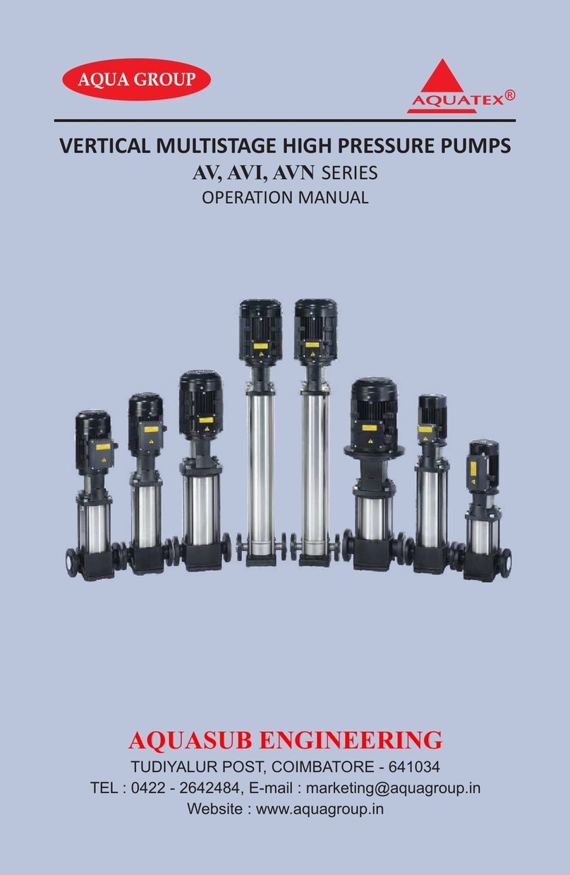
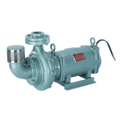
Aquasub engineering ADP 03SF User manual

SUBMERSIBLE DEWATERING PUMP
OPERATION MANUAL
ADP SERIES
AQUASUB ENGINEERING
TUDIYALUR POST, COIMBATORE - 641034
TEL : 0422 - 2642484, E-mail : [email protected]
Website : www.aquagroup.in

CONGRATULATIONS
Thank you for your purchase of 'TEXMO' Submersible Dewatering
pump. You are proud owner of new generation Dewatering pump. It is
designed and manufactured with stringent quality control to give trouble free
service for years. Please follow the instructions given in this manual to install
and maintain 'TEXMO' Submersible Dewatering Pump to get the best possible
and highly reliable operation. Utilise the services of a qualified technician for
installation.
Please inform the name plate details i.e. serial number of the pump,
type of pump etc. when you order for spare parts in the future.
After reading this operation manual, keep it safe and easily
accessible, so that it can be referred to whenever information is needed while
operating the equipment.
APPLICATION
‘TEXMO’ Submersible Dewatering pumps are designed for pumping
waste water from multi-storey, residential apartments, hotels and
restaurants. And also for dewatering of waste water from waste water
treatment plants, Pumping rain water from basement of buildings etc.
SPECIFICATION
¤ Phase and Power range........................ Single phase 0.5 HP - 3.0 HP
Three phase 0.5 HP - 3.0 HP
¤ Speed.................................................... 2850 rpm
¤ Voltage.................................................. Single phase 220 V
Three phase 380 V
¤ Frequency............................................. AC 50Hz
¤ Motor type............................................ Dry
¤ Starting method.................................... Single phase Capacitor run
Three phase DOL
¤ Insulation class..................................... "F" Class
¤ Duty...................................................... S1 Continuous
¤ Cable..................................................... 3 or 4 Core Double sheath
round PVC cable
¤ Impeller type........................................ Open Non Clog Impeller
¤ Maximum fluid temperature................ 40°C

CUT SECTION VIEW AND SPARE PARTS LIST
SINGLE PHASE MODELS
ADP 03SF
ADP 07SF
ADP 11SF
0.5 HP
1.0 HP
1.5 HP
¤
¤
¤
BRG.WASHER
CABLE COVER
BEARING HOUSING
1
2
1
CABLE BUSH GLAND
CABLE
O-RING
HEX.BOLT (C.COVER)
RESIN
STUD (CASING)
HANDLE
P.No PART NAME QTY
2
4.5
5
7.01
9
10
13
14
15
16
17
19
20
21
24
27
28
29
32
33
37
38
39
40
STATOR BODY ASSY
ROTOR SHAFT ASSY
TERMINAL COVER
CABLE BUSH
HEX.BOLT
BALL BEARING (BOT.)
MECHANICAL SEAL
O-RING
OIL CHAMBER
STUD
DOME CAP NUT
KEY (IMPELLER)
LOCK NUT
DOME CAP NUT
OIL
2
4
1
-
1
1
2
1
1
3
3
3
1
3
-
1
1
1
1
1
31
1
34
IMPELLER 1
CASING 1
O-RING
318
12 1
SPRING WASHER
36
41
3
HEX.BOLT (HANDLE) 2
BALL BEARING
7 1
4.5
2
5
9
12
7
7.01
13
14
15
16
17
18
19
20
21
42
24
27
28
29
31
32
33
34
37
38
40
41
HEX.BOLT (DELIVERY FLANGE)
42
43
44
DRAIN PLUG
DELIVERY FLANGE
1
1
2
45 HEX.NUT (DELIVERY FLANGE) 2
43
52
39
44
45
51
53
49
46
STRAINER 1
FLOAT
47
48
49
SUPPORT BUSH
CHEESE HEAD SCREW (STRAINER)
3
3
46
47
48
51
52
53
CHEESE HEAD SCREW (CAPACITOR CLAMP)
CAPACITOR
CAPACITOR CLAMP
1
1
1
1
50
LIP SEAL
50 1
10
36

CUT SECTION VIEW AND SPARE PARTS LIST
THREE PHASE MODELS
ADP 03T
ADP 07T
ADP 11T
0.5 HP
1.0 HP
1.5 HP
¤
¤
¤
4.5
2
5
13
14
15
16
17
19
20
21
42
40
41
43
52
39
44
45
53
50
10
7
7.01
24
27
28
29
31
32
33
34
37
38
51
36
BRG.WASHER
CABLE COVER
BEARING HOUSING
1
2
1
CABLE BUSH GLAND
CABLE
O-RING
RESIN
STUD (CASING)
HANDLE
P.No PART NAME QTY
2
4.5
5
7.01
10
13
14
15
16
17
19
20
21
24
27
28
29
32
33
37
38
39
40
STATOR BODY ASSY
ROTOR SHAFT ASSY
CABLE BUSH
HEX.BOLT
BALL BEARING (BOT.)
MECHANICAL SEAL
O-RING
OIL CHAMBER
STUD
DOME CAP NUT
KEY (IMPELLER)
LOCK NUT
DOME CAP NUT
OIL
2
4
1
-
1
1
2
1
1
3
3
3
1
3
-
1
1
1
1
31
1
34
IMPELLER 1
CASING 1
SPRING WASHER
36
41
3
HEX.BOLT (HANDLE) 2
BALL BEARING
7 1
HEX.BOLT (DELIVERY FLANGE)
42
43
44
DRAIN PLUG
DELIVERY FLANGE
1
1
2
45 HEX.NUT (DELIVERY FLANGE) 2
STRAINER 1
SUPPORT BUSH
CHEESE HEAD SCREW (STRAINER)
3
3
51
52
53
LIP SEAL
50 1
49
FROM CONTROL PANEL
FLOAT
49 1

DISASSEMBLY OF PUMP
For inspecting or cleaning the specified pump components please
follow the given guidelines and the sequence shown in figure.
In case of any replacement of components or sealing system
maintenance contact the dealer where the pump was purchased or
the "AQUASUB ENGINEERING's" sales office in your area for
specialized service. Do not try to disassemble any unspecified part of
pump, as it may lead to severe damage to the pump or personal
injuries.
SEQUENCE DIAGRAM FOR DISASSEMBLY
REASSEMBLY OF PUMP
Reassembly of the pump can be done by reversing disassembly
procedure. Make sure all the components are clean and free from damages.
Tighten the bolts and nuts properly to avoid leakage and vibration.
1 2 3 6 5 8 7
9 10 4

GENERAL INSTALLATION PRECAUTIONS
Do not use this pump for oil or toxic, acetic, corrosive and inflammable
liquids. Pumping inflammable liquids could cause explosion.
Do not use this pump for pumping potable liquids, it is danger for health.
Do not use cable for lifting the pump. Do not damage, fold, twist, make
alterations or bundle the cable.
The rope or chain for suspending the pump during installation that
accommodates the weight of the pump should be thick and make sure, that
does not get twisted. Damages in rope or chain can cause the pump to fall.
For better performance avoid flexible hose and use rigid pipe. Excessive
bending of the discharge pipe could obstruct the water flow, reduce the
discharge volume or clog the pipe with mud, which could affect pump
performance. Route the pipe as straight as possible.
Use a power supply cable that has sufficient rating and has been exclusively
provided for the pump. Sharing power cables with other equipments, can
lead to abnormal heat at the plug outlet and it can lead to fire.
Provide proper earthing. Do not connect the earthing wire to water pipe,
lightening rod or telephone earth wire. Improper earthing could cause
electrical shock.
To verify the insulation of the motor, use megger. Insulation resistance should
be 20MΩ minimum.
It is recommended to use an Earth Leakage Circuit Breaker (ELCB) to connect
the pump with main supply for safe operation.
Do not place the pump in the sludge, as it may lead to chocking of the pump
impeller.

AUX. WINDING
MAIN WINDING
RUNNING
CAPACITOR
THERMAL
SWITCH
FLOAT
SWITCH
NEUTRAL PHASE
R
YB
LINE 1
LINE 2
LINE 3
STARTER
ELECTRICAL CONNECTION
CONNECTION DIAGRAM
SINGLE PHASE CONNECTION THREE PHASE CONNECTION
CIRCUIT DIAGRAM
CAPACITOR RATINGS FOR SINGLE PHASE MODELS
ADP03SF 15 MFD, 440 V, 50Hz, Capacitor Run
ADP07SF 25 MFD, 440 V, 50Hz, Capacitor Run
ADP11SF 36 MFD, 440 V, 50Hz, Capacitor Run
¤¤
¤
¤
RED YELLOW
BLUE
PUMPSET CABLE
PHASE EARTH
NUETRAL
POWER SUPPLY
RED
YELLOW
BLUE
PUMPSET CABLE
L1 EARTH
L2
GREEN
L3
STARTER

OPERATION PRECAUTIONS
Do not run the pump dry, it could lead to product damage.
Ensure the free movement of float switch. Sump wall or any other structure
should not obstruct the free movement of float switch.
Switch off the power supply and ensure the impeller fully stop, before
changing rotation or making any other adjustments.
If you find any abnormalities like vibration, noise, smell etc.. in the pump
during trial operation, switch off the pump and contact the dealer where
this pump was purchased or the "AQUASUB ENGINEERING's" sales office in
your area.
Do not use this pump for hot liquids exceeding 40°C temperature, it may
lead to product failure.
Do not switch on the pump if there is any human contact with the pumping
water. If any electrical leakage occurs it could be harmful.
TRIAL OPERATION
The Submersible Dewatering pumps
are equipped with float switch which can
automatically switch "on" and "off" the
pump by sensing water level.
Trial operation can be done before installing
the pump in pit, by following below said
procedure,
1. By default, float switch will be in
downward direction. In this position switch
on the pump, ensure that the pump is in
"off" condition.
2. Move the float switch upward and
ensure that the pump starts.
3. Move the float downward and ensure
that the pump stops.
Repeat this procedure for 2 to 3 times and ensure that the pump is
working normally.
ON
OFF

Disconnect the power supply before starting maintenance or inspection of
the pump to avoid electrical shock.
Ensure the pump is intact, free from damage and has no loose components.
Use appropriate tools for executing maintenance, or it may lead to
component damage or personal injuries.
If you find any damages or abnormalities like vibration, noise, smell etc. in the
pump, switch off the pump and contact the dealer where this pump was
purchased or the "AQUASUB ENGINEERING's" sales office in your area for
proper maintenance.
MAINTENANCE
For uninterrupted performance, planned maintenance and inspection
are indispensable. Please follow below guidelines while maintaining or
inspecting the pump.
MAINTENANCE PRECAUTION
REVERSE FLUSHING OF THE PUMP
It is a simple procedure to clean impeller and casing by forcing water
from delivery side. It is recommended to follow this
procedure once in a week to have long trouble free operation.
by an external pump
OIL INSPECTION AND CHANGING
INSPECTING OIL : It is recommended to
inspect the oil for every 1000 Hrs of
usage, or once in six months whichever
is earlier. Remove the drain plug by a
screw driver and take out a small
amount of oil by slightly tilting the
pump. If the oil looks like milky or
intermixed with any other content, the
oil is contaminated.
It may be due to the failure of sealing system, which should be repaired
immediately. It can be solved by disassembling the pump and replacing
relevant components and replacing oil.
REPLACING OIL : It is recommended to change the oil for every 2000 Hrs of
usage, or once in a year whichever is earlier. Drain oil completely then pour 0.3
litres of “SAE 20/40 OIL (coolant oil)” or "PENTAGON COOLCUT S OIL" and
close the drain plug.

INSTALLATION PRECAUTIONS
PRODUCT INSPECTION
Inspect the purchased pump for damage or leakage during
transportation. And make sure all bolts and nuts are tightened properly.
If you find damage or discrepancy in the product, contact the dealer
where the pump was purchased or the "AQUASUB ENGINEERING's"
sales office in your area.
TYPICAL INSTALLATION
A typical installation diagram is shown below. Please follow the given
installation precautions before and during installation.
For three phase models it is recommended to use a control panel with
single phase prevention, overload relay and control for float switch
operation.
Cable
Discharge pipe
Chain or Rope
Pump
Sludge
( Place the pump above sludge)
Minimum water lavel
From control panel
(For three phase)
With pump
(For single phase)
Single phase models Three phase models

TROUBLE SHOOTING
If you find any trouble during operation of the pump, please follow the
guidelines to overcome some of the troubles given below.
TROUBLE PROBABLE SOLUTION
Conduct trial operation after maintenance or inspection.
Dispose replaced components and oil with appropriate care, to save
environment.
For unsolvable troubles in the pump, contact the dealer where this
pump was purchased or the "AQUASUB ENGINEERING's" sales office
in your area for specialized service.
Do not try to solve unspecified troubles of pump, as it may lead to
severe damage to the pump or personal injuries.
Pump doesnot start
Or Starts but stops
Immediately
Low delivery rate or
no delivery.
Pump generates
vibration or
excessive noise.
Pump does not
stop automatically
Motor not running
1. Check for overheat, if overheated allow the pump
to cool down. Pump may be tripped by thermal
overload protector.
2. Check for impeller choke.
1. Check proper function of float switch
1. Ensure proper installation
2. Check the bearing, if damaged change it.
1. Check power supply,
2. Ensure the strainer is free from blocks,
3. Ensure that the direction of rotation is correct,
4. Make sure for free rotation of impeller,
5. Check for blocks in delivery line,
6. Check the impeller, if damaged or worn change it.
1. Check the power supply.
2. Ensure float switch operation and water level,
3. Check that the pump is not placed in sludge.

NOTES

WARRANTY DECLARATION
WARRANTY FOR DEWATERING PUMP
AQUASUB ENGINEERING warrants to the purchaser of this TEXMO product, that
for a period of 12 months commencing from the date of purchase of the product, Aquasub
Engineering will repair or replace free of charge any part or parts of the product, should
AQUASUB ENGINEERING be fully satisfied in its sole discretion, that the defect/s is / are due
to faulty material or workmanship only. The warranty will be governed by the following
clauses:
1. Only AQUASUB ENGINEERING or their Authorised Service Agent / Dealer will repair /
replace all parts that are failing due to faulty material or defective workmanship
pertaining to the above product.
2. Only Aquasub Engineering or its Authorised Service Agent / Dealer can service / repair or
attend to install / reinstall the above product.
3. All expenses incurred in collecting the units or parts thereof from the Authorised Service
Centre or the Dealer of Aquasub Engineering as well as expenses incurred in connection
with deputing of service personnel / technicians towards to and fro travel conveyance
and other incidentals etc., will be borne by the customer.
4. The warranty extended therein is in lieu of all implied conditions and warranties under the
law and is confined to the repair or replacement of defective parts and does not cover any
consequential or resulting liability, damage or loss arising from such defects.
Furthermore, the warranty in no case, shall extend to the payment or any monetary
consideration whatsoever, of the replacement or return of the product as a whole.
5. The warranty is issued subject to jurisdiction of Coimbatore Court of Law.
6. The warranty is covered by Force Majeure clause. In the event if the above product
is struck by any natural calamity, this warranty stands null and void.
This Warranty is not valid in case of any of the following events.
a. This Pump is not used according to the instructions given in this Operation manual.
b. If the electrical power supply voltage is not within the stipulated norms.
c. Any repair work / installation carried out by a person other than Aquasub Engineering
Service Centre / Service Agent / Dealer.
WARRANTY CARD
(Please retain this for your personal record)
Authorised Dealer's seal Name & Signature of Authorised Dealer
Product Name & Model No. ....................... Serial No............................................
Name and Address of dealer ………...............……....................................................
Bill No. ........................................... Date of Purchase............................................

OTHER BUILDING SERVICES PRODUCTS
Hydropneumatic Pumping System
AQUASUB ENGINEERING
TUDIYALUR POST, COIMBATORE - 641034
TEL : 0422 - 2642484, E-mail : [email protected]
Website : www.aquagroup.in
Domestic Booster System, Water Transfer, Sewage, Drainage,
Construction Dewatering and
Vertical Inline High Pressure Pumpsets.
ADP-118/00 03-2016
This manual suits for next models
5
Table of contents
Other Aquasub engineering Water Pump manuals
Popular Water Pump manuals by other brands

Dionex
Dionex UltiMate 3000 Series operating instructions

Goulds Pumps
Goulds Pumps API3171 Installation, operation and maintenance manual

Metabo
Metabo TPF 18 LTX 2200 Original instructions

Oase
Oase Aquarius Eco Expert 28000 operating instructions

SKF
SKF LAGG 18M Instructions for use

LUBE
LUBE EGM-50TH-20N instruction manual