aquate 1350 Series User manual

Vers 3: March 2016
Installation and Operating Manual
1350 Series Aquate Pump Station
www.aquate.co.nz

Vers 3: March 2016
Foreward
This installation manual is a guide only. All relevent Health and Safety laws and codes of construction
must be adhered too and take precedence over any information in this manual. Installers must
practice good professional practice and are required to understand all National and Local regulations
in respect to the installation of drainage materials.
Contents
1 Product Records for the Homeowner ............................................................................................. 4
1.1 Installer details ........................................................................................................................ 4
1.2 Electricians details................................................................................................................... 4
1.3 Pump details............................................................................................................................ 4
1.4 What happens if the controller alarm activates?.................................................................... 4
2 Intended use.................................................................................................................................... 5
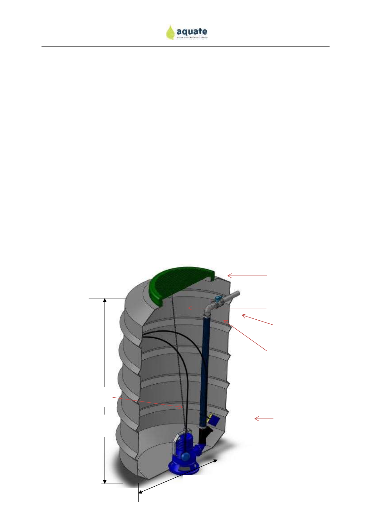
3 Technical Specifications................................................................................................................... 5
4 Holiday Mode (for wastewater pump stations only) ...................................................................... 7
5 Ventilation of the Pump Station...................................................................................................... 7
6 Safety instructions........................................................................................................................... 7
6.1 Maintenance and repair work................................................................................................. 7
6.2 Modifications to the pump station ......................................................................................... 7
6.3 Basic information about safety-conscious work ..................................................................... 7
6.4 Forbidden modes of operation ............................................................................................... 9
7 Tank Installation .............................................................................................................................. 9
7.1 Transport to Site...................................................................................................................... 9
7.2 Assembly require on-site......................................................................................................... 9
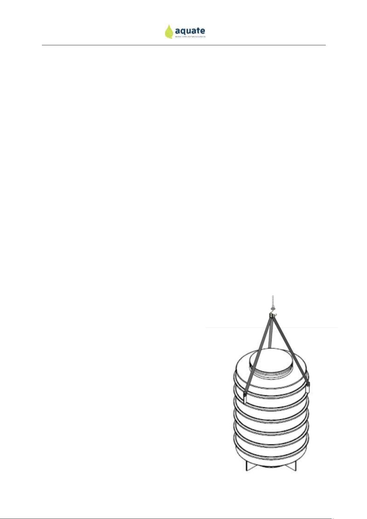
7.3 Lifting the Pump Chamber..................................................................................................... 10
7.4 Excavation and Backfilling ..................................................................................................... 10
7.5 High ground water conditions............................................................................................... 11
7.6 Inlet and Outlet Connections ................................................................................................ 12
7.7 Electrical outlet...................................................................................................................... 13
7.8 Typical Installation................................................................................................................. 13
8 Pump Installation .......................................................................................................................... 14
8.1 Safety..................................................................................................................................... 14
8.2 Vortex or Drainage Pump Models (DG or DR pumps)........................................................... 15
8.3 Grinder Pump Models (GR pumps) ....................................................................................... 18
8.4 Installation Notes .................................................................................................................. 20
8.5 Float Switch ........................................................................................................................... 21
9 Controller Installation.................................................................................................................... 22

Vers 3: March 2016
9.1 Vortex or Drainage Pumps (Zenit Blue DR or DG range)....................................................... 23
9.2 Grinder Pump Range (Zenit Blue GR Range) ......................................................................... 25
10 Trouble Shooting Guide................................................................................................................. 27
11 Tips and advice .............................................................................................................................. 30
12 Maintenance schedule .................................................................................................................. 31
12.1 Six monthly............................................................................................................................ 31
12.2 Annually................................................................................................................................. 31
13 Guarantees .................................................................................................................................... 32
14 Aquate Commissioning Sheet........................................................................................................ 33

Vers 3: March 2016
1Product Records for the Homeowner
This section is to be completed by the drainlayer or the homeowner upon installation of the pump
station and kept in case the pump station requires maintenance in the future.
1.1 Installer details
This pump station was installed on the …………………………………..20………..
Company name: ………………………………………………
Contact Person: ……………………………………………….
Telephone number: ……………………………………….. e-mail address:………………………………………………..
Other details………………………………………………………………………………………………………………………………………
1.2 Electricians details
This pump station was wired up by an electrician on the ………………………..20………..
Company name: ………………………………………………
Contact Person: ……………………………………………….
Telephone number: ……………………………………….. e-mail address………………………………………………..
Other details………………………………………………………………………………………………………………………………………
1.3 Pump details
The pump installed in this pump station is a ……………………………………………………………………………………..
Note: this can be found on the inside of the electrical controller. Typical codes are Zenit DG75, Zenit
DR75, Zenit GR100 or Zenit GR200.
1.4 What happens if the controller alarm activates?
An alarm will either indicate a pump failure or burnout or that the water level is high in the chamber.
The first point of contact should be with the drainlayer who installed the system. This drainlayer
should assess whether there is an electrical fault, a pump fault or a pump blockage. If the fault is
electrical, the electrician who installed the system should be contacted. If the pump is blocked, it can
be removed from the chamber on site and cleaned. If there is a mechanical failure with the pump,
the drainlayer should contact the local pump agent to assess the cause of the failure. Desist in using
water whenever possible until the system is operational again.

Vers 3: March 2016
2Intended use
The Aquate Pump Station is intended for conveying domestic wastewater or stormwater only. As
with any pumping system, large objects will block the system and must be prevented from entering
the system. A list of potentially damaging items are included below and further advice is detailed in
the Tips and Advice Section. The intended use also includes observance of the installation
instructions and commissioning and operating conditions. The owner is to follow the
recommendations in this operating manual.
Condoms
Cigarettes
Baby Wipes
Fat, grease or oil
Nappies
Paints
Rags/ Towels
Sanitary products
Hair
Plastic bags
Blood, meat flesh or skins
Table 1: Products prohibited to enter sewer connection
3Technical Specifications
Overall plant: Aquate Pump Station
Tank Volume: 1.35 m3
Weight of tank: 80 kg
Tank material: Polyethylene
Loading: The standard polyethylene lid is suitable for pedestrian loading. A concrete
lid can be supplied if traffic loading is required up to HN Loading.
Inlet Connections: the chamber comes with a Wallace seal to be fitted into the chamber on site
by the installer. This seal will prevent infiltration into the chamber
Outlet connection: A threaded BSP socket is installed for connection to the outlet pressure pipe
Dimensions: see drawing below
Designer: Aquate Ltd
Agent Hygrade Products

Vers 3: March 2016
Pump (your system will have one of the following pumps –check your quote for details).
Manufacturer: Zenit
Type: Drainage DR Blue 75, Vortex DG Blue 75 Grinder GR Blue 100 or Grinder GR
Blue 150
Connection: 230 V, 50 Hz
Power: 0.55 kW, 0.55 kW, 0.74 kW, 1.1 kW
Weight: 13.5 kg, 15 kg, 19 kg, 24 kg
Number: 1 unit
Controller
Manufacturer: N2P Controls
Type: AQP-01
Connection: 230 V, 50 Hz
Number: 1 unit
Material: UV Stabilised plastic construction for external locations.
Features IP Rating up to IP66, audio and visual alarms for high water and electrical
failure.
600mm clear opening.
Access lid designed for pedestrian loading
Pump type and size to suit
each application
Lifting strop for easy pump
removal
Hydrostatic flanges designed to
prevent floatation in area with
a high water table
Inlet seal supplied loose
for
easy installation on site
Threaded BSP Socket for
outlet connections
Quick release coupling for
pump removal
1750 mm
1075mm

Vers 3: March 2016
4Holiday Mode (for wastewater pump stations only)
If your dwelling will be unused for an extended period, the pump station should be flushed with
clean water before you leave the site to prevent the sewage from becoming septic. If this occurs,
unwelcome odours may result and solids from the sewage will settle out in the chamber and
potentially block the pump upon restart.
To flush the pump chamber, simply run a tap until the pump activates. A bath can also be filled and
drained into the pump chamber. If the chamber is empty, approximately 200 litres of water will be
required to activate the pump.
5Ventilation of the Pump Station
The pump station incorporates a very small gap between the lid and the chamber to provide the
required ventilation to the pump station in accordance with national and local plumbing code
requirements.
The on-site drainage network should also incorporate a terminal vent in accordance with New
Zealand plumbing and drainage requirements.
6Safety instructions
This operating manual contains basic information that must be
observed when operating and servicing the plant. This operating
manual must be kept accessible at the plant's place of installation.
The installation of the plant and electrical installation is to be
carried out according to their respective best practice guidelines
and to the standard expected by the profession in question.
This manual does not guarantee that all health and safety risks
have been identified. All sites are unique and a health and safety
review should be completed by the owners of the pump station.
6.1 Maintenance and repair work
Only the manufacturer or an approved company may carry out the maintenance and repair work.
Any work carried out by unauthorised personnel may result in the warranties for the system
becoming invalid.
6.2 Modifications to the pump station
The pump station should not be modified without the agreement of Aquate Ltd. Genuine spare
parts are essential for the operation of this unit and the use of any unauthorised components may
invalidate any warranties on the system.
6.3 Basic information about safety-conscious work
No work should be completed on the Aquate system other than by trained and approved personnel.
If work is undertaken, a full health and safety review is to be completed by the relevant contractor /

Vers 3: March 2016
workman. The aim of this is to identify all possible hazards and take measures to eliminate, isolate or
minimise them. The following section summarises important safety
information, however this should not be substituted for a full and thorough
site evaluation using the company’s own safety procedures.
Frequent risks when operating, checking and maintaining pumping stations
are:
Inflammations and infections
Danger of falling into the empty or filled tank
Danger of suffocation
Risks from electricity
6.3.1 Inflammations and infections
Sewage contains a multitude of germs, infectious pathogens (salmonella dysentery, typhoid fever,
paratyphoid fever, pneumonia), viruses (influenza, poliomyelitis, hepatitis, HIV) and worm eggs.
Therefore you should pay particular attention to hygiene.
You should observe and follow the instructions below:
Make sure all installers and technicians are sufficiently protected against poliomyelitis, tetanus,
hepatitis A and B through inoculation.
Thoroughly clean your hands with water and soap or hand cleansing paste after any contact
with sewage.
Always wear rubber gloves, particularly if you have an injury.
Do not eat, drink or smoke with dirty hands or in the vicinity of the pump station.
Wear separate protective and work clothing and keep them apart from your normal clothing.
Take off and wash your clothing immediately after you have finished
work.
Consult a doctor immediately if you swallow any sewage.
6.3.2 Danger of falling into the empty or full tank
To avoid falling into an empty or filled tank and/or chamber you should
Always have a firm foothold
Wear safety footwear
Cover access holes when not in use
6.3.3 Danger of suffocation
You must be aware of the production of toxic and explosive sewage gases in pump stations, which
can cause suffocation when you enter the tanks or confined areas where gases could accumulate. Do
not enter the tank under any circumstances. If the tank is to be entered by a contractor, standard
confined space procedures must be followed.

Vers 3: March 2016
There is a general ban on smoking in the vicinity of the pump stations (risk of explosion).
6.3.4 Risks from electricity
Before entering any part of the pump station and making contact with the water or working on or
near motorised equipment, make sure that the power to the relevant components are switched off
and safely isolated using standard isolation procedures.
6.3.5 Risks arising from non-observance of the safety instructions
A failure to comply with the safety instructions may cause risks to both persons as well as the
environment and machine. Non-observance of the safety instructions may result in the forfeiture of
any claims for damages.
Non-observance may, for example, result in the following risks:
Failure of important plant functions
Danger to persons due to electrical, mechanical and chemical / biochemical affects
6.4 Forbidden modes of operation
The operational safety of the supplied plant can only be guaranteed if it is used for the intended
purpose according to the operating instructions. Any operation outside its intended design may
result in damage to the plant and/or to a person.
7Tank Installation
The installation of the pump chamber is responsibility of the contractor. All Health and Safety
regulations must be complied with.
7.1 Transport to Site
The pump chamber will be delivered to site in an
vertical position and will be secured using the lifting
eyes on the side of the chamber.
7.2 Assembly require on-site
The pump chamber will come fitted with the internal
pipework fittings and control stand (if required). The
pump will be provided ready to be connected to the
outlet pipework via a quick release valve.
The control panel will be fitted separately once the unit
has been installed. This unit can either be located at the
pump chamber or can be installed on a nearby dwelling.
Electrical installation diagrams are enclosed.
The hole for the inlet pipe will need to be drilled on site
and a Wallace Seal will be supplied loose for this
connection. See below for additional details. The hole
Figure 2 –three point lifting of the
pump chamber

Vers 3: March 2016
for the Wallace seal must be located between the ribs of the pump chamber.
7.3 Lifting the Pump Chamber
The pump chamber has three lifting eyes with 50 mm holes in each lifting point. Suitable strops,
chains or ropes must be used when lifting the chamber into the ground. All relevant Health and
Safety regulations must be complied with to ensure the safety of all site personnel.
The chamber will weigh from 80kg (empty) to 100 kg (with pump fitted).
7.4 Excavation and Backfilling
All relevant National and Local Health and Safety regulation must be observed during the
installation of an Aquate Pump Station.
Procedure
1. The excavation must be at least 1.8m diameter wide to allow access around the tank for
pipe connections and compacting equipment. The depth of the excavation should be
approximately 1.8m deep.
2. The excavation should only be completed on the day of installation to prevent the hole
filling with rainwater or potential wall collapses.
3. All local regulations for benching of excavations must be observed. Excavations deeper
than 1.5m will require benching.
4. Ensure that a site assessment is completed prior to installation of the pump station.
Note any overhead power lines, underground services or any other potential hazards
5. Place 100mm of suitable material such as a fine grade scoria, sand or GAP7 in the
bottom of the excavation. Compact well and level.
6. Place pump station in the centre of the excavation and ensure it is level.
7. Add 300mm of suitable backfill and compact evenly all around the pump station
8. Continue with 300mm layers of backfill.
9. Connect inlet and outlet pipes when required
10. Landscape around the pump chamber to suit
11. Ensure the lid of the pump station is above the surrounding ground and the ground is
contoured so ponding does not occur around the pump station.
12. Electrical connection to be completed by a certified electrician

Vers 3: March 2016
7.5 High ground water conditions
For sites where the expected ground water table is higher than half way up the pump station. It is
recommended that low strength concrete be poured around the base of unit such that it covers the
flange at the base of the pump station. See drawing below for details.
Figure 3 –backfilling the excavation
1750mm
1750mm

Vers 3: March 2016
7.6 Inlet and Outlet Connections
The inlet hole must be completed on site once the gravity line into the pump chamber has been laid
and the minimum falls have been achieved.
A hole needs to be drilled at the appropriate height, taking care to ensure it is between the ribs in
the pump station.
A Wallace Seal is provided with the unit to provide a simple reliable seal into the pump chamber.
Simply drill the hole, fit the seal and push in the pipe.
The standard hole required for a 100mm stormwater or wastewater pipe is 121mm.
The outlet connection will come pre-installed in the unit. A standard BSP threaded connector is
supplied with the pump station.
Note: the drainlayer will be required to lower the rising main from the outlet point to ensure the
rising main has sufficient cover. This is typically >600mm.
Wallace Seal
Figure 4 –Inlet connection
200mm to invert of
outlet pipe
Drainlayer to lower pipe
on site to meet minimum
cover requirements
(typically >600mm)

Vers 3: March 2016
7.7 Electrical outlet
40mm Wallace Seal is provided with the unit to provide a simple reliable seal for the electrical
cables. This is designed to fit 40mm electrical conduit.
Simply drill the hole, fit the seal and push in the conduit. The standard hole required for a 40mm
Wallace seal is 52 mm.
7.8 Typical Installation
Figure 5 - Typical Installation
Things to note:
1. Ground levels –ensure the surrounding ground is contoured so ponding does not occur
around the pump station when it rains.
2. Inlet hole to be drilled between the ribs in the pump chamber
3. Gravity inlet pipe to achieve minimum fall requirements as per NZ standards
4. Compaction of the backfill around the tank is critical
Electrical controller –can be
located at the pump station or on
the house or nearby dwelling.
Backfill as per local
regulations.. Requires
compacting every 300mm
Threaded BSP socket
for outlet pipe
connection.
Gravity inlet pipe.
Electrical cable to be supplied and
installed by a certified electrician as per
local and national electrical regulations
Wallace seal for inlet.
Hole to be drilled on site.
100mm sub base -
compacted. Material to be
fine grade scoria or similar.
Important: Do not
bury the lid.

Vers 3: March 2016
8Pump Installation
8.1 Safety
WARNING: Never lift the pump using the electrical cable or float switch cable as this can
damage the cables. Only use the rope provided.
Do not allow the electric pump to be used by children or non-qualified persons.
Do not use the electric pump to decant inflammable fluids.
Do not install the electric pump in confined areas where there may be gas or a risk of
explosions.
Do not modify the pump for any reason (such as fitting couplings or carrying out drilling or
finishing work, etc...).
Do not put your fingers or other objects in the intake and delivery holes. Be particularly
careful when using the GRBlue model, which is fitted with a shredder blade in the intake
area.
Ensure the end of the electric power cable does not come into contact with the fluid.
When carrying out installation, checking or maintenance operations on the electric pump,
always use Personal Protective Equipment (PPE), i.e. regulation garments and equipment.
Accident-prevention shoes and gloves, safety goggles and leather aprons must be always be
worn.
Before handling the fitted product, wash it thoroughly with running water.
Only connect the electricity supply once the electric pump has been correctly installed.
Unplug the unit at the mains before carrying out any maintenance and/or cleaning
operations or when simply removing the pump from the fluid.
Use jets of water and/ or detergent to clean the machine before carrying out any
maintenance and/ or cleaning operation.
Do not obstruct the fluid intake and delivery pipes.
In the event of damage, stop the pump immediately.
Contact an authorised Zenit technical service centre for repairs and always request the use
of original spare parts.
Failure to comply with the above could result in impaired pump safety, in addition to
forfeiture of the warranty.

Vers 3: March 2016
8.2 Vortex or Drainage Pump Models (DG or DR pumps)
Step 1
Open the lid of the pump chamber and unscrew the quick release union couple located 200mm
below the lid. ‘
Remove the pipework below the coupler as shown in photo 1
Photo 1
Step 2
Unscrew the hex nipple form the barrel union as shown
Photo 2

Vers 3: March 2016
Step 3
Remove the pump from the box and screw the
hex nipple into the outlet as shown
Photo 3
Step 4
Screw the barrel union into the hex nipple as
shown
Photo 4

Vers 3: March 2016
Step 5
Secure the electrical cable to the
pipework with the four cable ties
supplied.
Photo 5
Step 6
Tie the rope supplied to the handle of the pump
Step 7
Lower the complete pump and pipework unit into the
pump station (to a central position)
WARNING: Never lift the pump using the electrical
cable or float switch cable as this can damage the
cables. Only use the rope provided.
Step 8
Screw the quick release coupler back together and
the unit is ready to be wired up.
Photo 6

Vers 3: March 2016
8.3 Grinder Pump Models (GR pumps)
Step 1
Open the lid of the pump chamber and unscrew the quick release union couple located 200mm
below the lid. ‘
Remove the pipework below the coupler as shown in photo 1. The elbow as shown in the photo will
be supplied loose in the controller box.
Photo 1
Step 2
Remove the pump from the box screw the elbow into the pump as shown below
WARNING: Never lift the pump using the electrical cable or float switch cable
Photo 2

Vers 3: March 2016
Step 3
Screw the hex nipple into the elbow as shown
Photo 3
Step 4
Secure the electrical cable to the pipework
with the four cable ties supplied.
Photo 4

Vers 3: March 2016
Step 5
Tie the rope supplied to the handle of the pump
Step 6
Lower the complete pump and pipework unit into the
pump station (to a central position)
WARNING: Never lift the pump using the electrical
cable or float switch cable as this can damage the
cables. Only use the rope provided.
Step 7
Screw the quick release coupler back together and
the unit is ready to be wired up.
Photo 5
8.4 Installation Notes
If the pump is installed inside a shaft, this must be large enough to allow the float switch, if installed,
to move freely. The manufacturer recommends the use of shafts which are no smaller than 500mm x
500mm x 500mm. (Fig. 1)
WARNING: Check that the submersible pump has been primed. In some cases, an air bubble may
form in the upper part of the pump body, which prevents liquid pumping.
WARNING: Before the installation and/or the start-up of the pump after a long period of inactivity,
turn the shaft with the box wrench to ensure that it rotates freely.
Table of contents
Popular Water Pump manuals by other brands

AMT
AMT 4230-97 Specifications information and repair parts manual

Wayne
Wayne WaterBug WWB Quick start instructions

HEISSNER
HEISSNER HFP5000-00 Instructions for use

Cheonsei
Cheonsei KEMPION PDS Series instruction manual

Tsurumi Pump
Tsurumi Pump LB Series Starting and operating instruction

DROPSA
DROPSA SUMO II Series User and maintenance manual