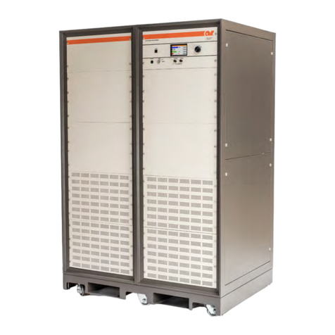
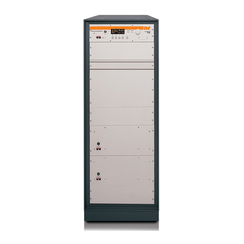
AR 2500L Service manual

Operating and
Service Manual
2500L
Model
10005070
Part Number
Serial Number
160 School House Road, Souderton, PA 18964 • 215-723-8181 • Fax 215-723-5688 • www.arworld.us


EC Declaration of Conformity
We; AR Worldwide
160 School House Road
Souderton, Pa. 18964
declare that our product;
the Model 2500L, 2500LM1, 2500LM3, 2500LM4, 2500LM5, 2500LM6, 2500LM7 and
2500LM9 RF amplifiers
to which this declaration relates is in compliance with the requirements of the;
EEC EMC Directive (89/336/EEC) in accordance with Article 10 (2) of the directive,
with the provision that the user must install the equipment as directed by the
“Instructions for European EMC Conformity” in the Operating and Service Manual.
This declaration is made on the basis of competent body issued
EC Certificate of Conformity No.: E9 96 01 25528 007.
Donald R. Shepherd
President


Instructions for European EMC Conformity
WARNING
It is the responsibility of the user of this equipment to provide electromagnetic shielding, filtering and isolation
which is necessary for EMC compliance to Directive 89/336/EEC. The equipment must therefor be operated in a
shielded area which provides a sufficient level of attenuation to meet the radiated emissions and immunity
specifications. All AC, DC and Control lines connected to the equipment and entering or exiting the shielded
area must have sufficient isolation to meet the conducted emissions and immunity specifications. The following
inimum levels are suggested for use in accordance with the rated power of the equipment.
m
Rated Power Minimum shielding attenuation Minimum line isolation
100 watts 50 dB 50 dB
101 - 1000 watts 60 dB 60 dB
1001 - 10,000 watts 70 dB 70 dB
Since this equipment is designed to generate high levels of Radio Frequency energy, it is also essential that the
user read and follow the “Instructions for Safe Operation” in this manual. If other equipment is operated in the
hielded room it may be disturbed by the amplifier.
s
ACHTUNG
Der Benutzer dieses Gerätes ist dafür verantwortlich, daß die elektromagnetische Abschirmung und Filterung
gewährleistet ist, welche gemäß Richtlinie 89/336/EEC notwendig ist. Das Gerät muß deshalb in einem
geschirmten Raum betrieben werden, welcher eine ausreichenden Schirmung bietet, um die Emissions- und
Störfestigkeitsspezifkation einzuhalten. Alle Wechsel- und Gleichspannungsleitungen sowie Steuerleitungen,
die mit dem Gerät verbunden sind und in den geschirmten Raum von außen hereingeführt werden, müssen
ausreichend gefiltert sein, um die Emissionsspezifkation einzuhalten. Es werden folgenden Minimalwerte der
chirmdämpfung und Filterung in den unterschiedlichen Leistungsklassen empfohlen.
S
Hochfrequenzleistung min. Schirmdämpfung min Filterdämpfung
100 Watt 50 dB 50 dB
101-1000 Watt 60 dB 60 dB
1001-10.000 Watt 70 dB 70 dB
Falls andere elektrische oder elektronische Geräte gleichzeitig mit dem Gerät betrieben werden, kann es zu
Beeinflussungen kommen. Da das Gerät zur Erzeugung von Hochfrequenzenergie dient ist es daher auch
nbedingt notwendig, daß der Benutzer die Sicherheitsvorschriften in der Bedienungsanleitung liest und einhält.
u
AVERTISSEMENT
Il est de la responsabilité de l'utilisateur de cet équipement d'assurer la protection électromagnétique, le filtrage
et l'isolation nécessaires, afin de se conformer à la directive 89/336/EEC concernant la C.E.M. Par conséquent,
cet équipement doit être mis en fonctionnement dans une enceinte d'atténuation suffisante pour satisfaire aux
spécifications d'émissivité et de susceptibilité. Toutes les alimentations alternatives, continues ainsi que les
liaisons de contrôle connectées à cet équipement, qui entrent ou sortent de cette enceinte doivent avoir une
isolation suffisante pour satisfaire aux spécifications concernant les émissions conduites et d'immunité. Pour une
utilisation conforme, les niveaux d'atténuation minimums suivants sont suggérés en fonction de la puissance de
ortie de l'équipement:
s
Puissance de sortie Atténuation minimum de l'enceinte Isolation minium de la ligne
100 Watts 50 dB 50 dB
101 à 1.000 Watts 60 dB 60 dB
1.001 à 10.000 Watts 70 dB 70 dB
Puisque cet équipement est destiné à générer de forts niveaux R.F., il est essentiel que l'utilisateur se conforme
aux instructions de sécurité indiquées dans ce manuel. Tout autre équipement en fonctionnement dans la cage de
Faraday peut-être perturbé par 1'amplificateur.


INSTRUCTIONS FOR SAFE OPERATION
BEFORE APPLYING POWER
Review this manual and become familiar with all safety
markings and instructions.
Verify that the equipment line voltage selection is
compatible with the main power source.
Protection provided by the equipment may be
impaired if used in a manner not specified by Amplifier
Research.
INTENDED PURPOSES
This equipment is intended for general laboratory use in a
wide variety of industrial and scientific applications. It is
designed to be used in the process of generating,
controlling, and measuring high levels of electromagnetic
Radio Frequency (RF) energy. Therefore, the output of the
amplifier must be connected to an appropriate load such as
an antenna or field-generating device. It is the
responsibility of the user to assure that the device is
operated in a location which will control the radiated
energy such that it will not cause injury and will not
violate regulatory levels of electromagnetic interference.
HAZARDOUS RF VOLTAGES
The RF voltages on the center pin of the RF output
connector can be hazardous. The RF output connector
should be connected to a load before AC power is applied
to the amplifier. Do not come into contact with the center
pin of the RF output connector or accessories connected to
it. Place the equipment in a non-operating condition before
disconnecting or connecting the load to the RF output
connector.
SAFETY GROUND
This equipment is provided with a protective earth
terminal. The main power source to the equipment must
supply an uninterrupted safety ground of sufficient size to
the input wiring terminals, power cord, or supplied power
cord set. The equipment MUST NOT BE USED if this
protection is impaired.
PHYSICAL DAMAGE
The RF amplifier should not be operated if there is
physical damage, missing hardware, or missing panels.
MAINTENANCE CAUTION
Adjustment, maintenance, or repair of the equipment must
be performed only by qualified personnel. Hazardous
energy may be present while protective covers are
removed from the equipment even if disconnected from
the power source. Contact may result in personal injury.
Replacement fuses are required to be of specific type and
current rating.
SAFETY SYMBOLS
This symbol is marked on the equipment
when it is necessary for the user to refer to
the manual for important safety
information.
Dangerous voltages are present. Use
extreme care.
CAUTION: The caution symbol denotes
a potential hazard. Attention must be
given to the statement to prevent damage,
destruction, or harm.
Indicates protective earth terminal.
RANGE OF ENVIRONMENTAL CONDITIONS
This equipment is designed to be safe under the following
environmental conditions:
•Indoor use
•Altitude up to 2000M
•Temperature of 5°C to 40°C
•Maximum relative humidity 80% for temperatures up
to 31°C. Decreasing linearly to 50% at 40°C.
•Main supply voltage fluctuations not to exceed ± 10%
of the nominal voltage or minimum and maximum
autoranging values.
•Pollution degree 2: Normally non-conductive with
occasional condensation. While the equipment will
not cause hazardous condition over this environmental
range, its performance may vary.
COOLING AIR
Care should be exercised not to block the cooling air inlets
or outlets. Cooling air blockage can result in damage to the
RF amplifier or intermittent shut-downs.

NOTICE
The amplifier described in this text is basically designed for operation with signal frequencies from 10 kHz to 220
MHz.
Variations in alignment and component selection will be determined by the model number ordered.
See the amplifier specification sheet for frequency range and power output. The Model 2500L is referenced
throughout the text to explain operation. The appropriate model number should be substituted for individual
amplifiers.


TABLE OF CONTENTS
TABLE OF CONTENTS .................................................................................................. i
1. GENERAL INFORMATION ............................................................................. 1
1.1 General Description ............................................................................................... 1
1.2 Power Supplies ...................................................................................................... 1
1.3 Cooling System...................................................................................................... 1
1.4 Specifications......................................................................................................... 1
1.5 Installation ............................................................................................................. 2
1.5.1 Location ................................................................................................................. 2
1.5.2 Primary Power Connections .................................................................................. 2
1.5.3 Connections to Water Supply (Liquid Cooled Model Only) ................................. 4
1.5.4 Coolant................................................................................................................... 4
1.5.5 General CAUTION Notes...................................................................................... 5
2. OPERATING INSTRUCTIONS ........................................................................ 9
2.1 General................................................................................................................... 9
2.2 Amplifier Operation............................................................................................... 9
3. THEORY OF OPERATION ............................................................................ 15
3.1 Introduction.......................................................................................................... 15
3.2 Gain Control ........................................................................................................ 15
3.3 Low Level Amplifier ........................................................................................... 15
3.4 Driver Amplifier .................................................................................................. 16
3.4.1 Frequency Range 10 kHz to 220 MHz ................................................................ 16
3.4.2 Frequency Range 1 MHz to 220 MHz................................................................. 16
3.5 Final Amplifier .................................................................................................... 17
3.6 Power Supply....................................................................................................... 19
3.6.1 Side Panel Assembly, A3..................................................................................... 19
3.6.2 Control Panel Assembly, A4 ............................................................................... 21
3.6.3 Coolant Pump Assembly, A5............................................................................... 21
3.6.4 Rear Panel Assembly ........................................................................................... 23
4. MAINTENANCE............................................................................................... 29
4.1 General Maintenance Information ....................................................................... 29
4.2 Disassembly Procedures ...................................................................................... 29
4.2.1 Driver Amplifier .................................................................................................. 29
4.2.2 Final Amplifier .................................................................................................... 30
4.2.3 Removal of Printed Circuit Boards from Rear Panel of Power Supply............... 31
4.2.4 Access To Primary Taps of Power Transformers ................................................ 31
4.2.5 Reassembly .......................................................................................................... 31
4.3 Maintenance of Cooling System.......................................................................... 31
4.4 Troubleshooting................................................................................................... 32
4.4.1 Tube Replacement Procedure .............................................................................. 33
4.4.2 Procedure For Adjusting Driver and Final Amplifier Grid Bias ......................... 34
4.4.3 Tube Test Procedure ............................................................................................ 34
4.5 Servicing Etched Circuit Boards.......................................................................... 36
i

Model 2500L
ii

1. GENERAL INFORMATION
1.1 GENERAL DESCRIPTION
The Model 2500L is a self-contained, broad band amplifier intended for laboratory applications where
instantaneous bandwidth, high gain and high power output are required. When used with a swept frequency
signal source it will provide a minimum of 2500 watts of swept CW power. Provisions are included to obtain
outputs of 100 watts CW as well as 4000 watts when excited with a gate/blank input in pulse mode having a
15% duty cycle or less. The unit employs the most up-to-date design technology in both its solid-state low
level amplifier and vacuum tube driver and final amplifiers. A crowbar circuit shuts down the high voltage
within 30 microseconds should an arc or fault develop in a tube. All operating controls are functionally
grouped on the front panel to simplify operator use. They include modern, lighted push-button switches for
the command functions; POWER, STANDBY, OPERATE and PULSE, a gain control for setting the output
level of the amplifier, and a switch to select outputs of either 100 watts or 2500 watts CW (4000 watt pulses).
A single meter and selector switch are provided for monitoring the operating voltages and currents of both the
driver and final amplifiers as well as the 3 phase line voltages.
Unique circuitry developed by Amplifier Research permits operation without shut down or damage regardless
of source or load impedance thus making the unit the most versatile unit available for laboratory use. Typical
applications include antenna and component testing, watt meter calibration, EMI susceptibility testing, and
NMR applications.
1.2 POWER SUPPLIES
The unit incorporates both regulated and unregulated self-contained power supplies. A 3 phase circuit
breaker is provided on the rear of the power supply chassis. Since the amplifier is available in several
different models and with various primary power options, see the table shown below for exact power supply
requirements. The total power consumption is approximately 21 KVA for each model.
Primary voltage Frequency Primary Circuit breaker
200/208 VAC 50/60 Hz 60A
380/415 VAC 50/60 Hz 30A
1.3 COOLING SYSTEM
Due to the high dissipation from the plates of the final amplifier tubes, liquid cooling is required to remove
the heat. The unit incorporates a cooling system consisting of a coolant reservoir, pump, heat exchanger, and
interlock switches which prevent operation when the coolant level or flow is insufficient or the temperature is
excessive. The ultimate removal of heat is accomplished using the recommended liquid/liquid heat exchanger
which uses ordinary tap water. Liquid/air cooling is also available. Other components are cooled by forced
air.
1.4 SPECIFICATIONS
See the AR Worldwide Data Sheet at the end of this section for detailed specifications.
Rev A 1

Model 2500L
1.5 INSTALLATION
Before proceeding, thoroughly inspect the amplifier for signs of physical damage which may have been
incurred during shipment and completely read the following installation and operating instructions paying
attention to all CAUTION notes. See Envelope Drawing Number 10020178.
1.5.1 Location
Select an operating location which will permit free air circulation around the amplifier cabinet. The unit
utilizes extensive forced air cooling and should not be located where the normal flow of air into or exiting
from the unit will be restricted, diverted, or re-circulated through the unit itself. For example, do not place the
unit in a location having a low overhead shelf, as this will restrict and re-circulate the air flow from the
amplifier exhaust ports located on the rear of the cabinet.
CAUTION:
Under normal operating conditions the exhaust air temperature from the
unit may exceed 80°C. Do not locate any heat sensitive equipment or
materials in the direct path of the exhaust air.
1.5.2 Primary Power Connections
The primary power may be supplied through a flexible cord, by wiring within a rigid conduit, via B-X cable
or any other means desired by the user and acceptable to local electrical codes and ordinances. Entrance for
the primary connection should be made by punching a hole at any convenient location in the base of the
amplifier cabinet. This hole should be of a size suitable for your particular installation requirements. A hole
is located in the bottom plate of the amplifier immediately below the primary power connection terminal strip
to provide the final access for the primary power cable. The unit is available in several different primary
voltage options.
1.5.2.1 200/208 VAC, 50/60 Hz Primary Power Option
With this option the amplifier can be operated on either 200 VAC or 208 VAC, 50/60 Hz, 3 phase primary
power. It has been prewired at the factory for operation with the primary power voltage specified by the
customer. The amplifier can be readied for operation by connecting the 3 phase primary power lines to
terminals 1, 2, and 3 and a ground wire to terminal 4 of the terminal block on the rear of the power supply
chassis inside the rear door.
When operating from 200/208 VAC a 60 ampere service is required.
CAUTION:
The primary power must be supplied through a slow acting, 3 phase
common trip circuit breaker. The use of fuses or individual breakers on
each line may cause damage if only one phase is disconnected.
If it is desired to operate the unit from a 3 phase source of a different voltage than that wired at the factory, it
is necessary to change the primary transformer taps of the A8T1 and T2. See the following chart for tap
connections.
2 Rev A

Model 2500L
CONNECT TO
WIRE FROM 200 VAC 208 VAC
A9K2-6 A8T1-Z1 A8T1-X1
A9K2-5 A8T1-Z2 A8T1-X2
A9K2-4 A8T1-Z3 A8T1-X3
A9K3-T1 T2-X1 T2-W1
A9K3-T2 T2-X2 T2-W2
A9K3-T3 T2-X3 T2-W3
A9K4-T1 T2-Z1 T2-Y1
A9K4-T2 T2-Z2 T2-Y2
A9K4-T3 T2-Z3 T2-Y3
See Schematic Diagram Number 10019257.
1.5.2.2 380/415 VAC, 50/60 Hz Primary Power Option
With this option the amplifier can be operated on either 380 VAC or 415 VAC, 50/60 Hz, 3 phase primary
power. It has been prewired at the factory for operation with the primary power voltage specified by the
customer. The amplifier can be readied for operation by connecting the 3 phase primary power lines to
terminals 1, 2, and 3 and a ground wire to terminal 4 of the terminal block on the rear of the power supply
chassis inside the rear door.
When operating from 380/415 VAC a 35 ampere service is required.
CAUTION:
The primary power must be supplied through a slow acting, 3 phase
common trip circuit breaker. The use of fuses or individual breakers on
each line may cause damage if only one phase is disconnected.
If it is desired to operate the unit from a 3 phase source of a different voltage than that wired at the factory, it
is necessary to change the primary transformer taps of the A8T1 and T2. See the following chart for tap
connections.
CONNECT TO
WIRE FROM 380 VAC 415 VAC
A9K2-6 A8T1-Z1 A8T1-X1
A9K2-5 A8T1-Z2 A8T1-X2
A9K2-4 A8T1-Z3 A8T1-X3
A9K3-T1 T2-X1 T2-W1
A9K3-T2 T2-X2 T2-W2
A9K3-T3 T2-X3 T2-W3
A9K4-T1 T2-Z1 T2-Y1
A9K4-T2 T2-Z2 T2-Y2
A9K4-T3 T2-Z3 T2-Y3
See Schematic Diagram Number 10019257.
Rev A 3

Model 2500L
1.5.3 Connections to Water Supply (Liquid Cooled Model Only)
Before the unit is turned on, connections must be made to the cooling water taps located on the upper rear
panel. A tap water source such as is normally encountered in the average building with a minimum flow rate
of 5 GPM (19 liter/min.) and a maximum temperature of 20°C is required. The tap water source is connected
to the hose connection WATER INLET and the waste water is removed from the hose connection WATER
OUTPUT. The outlet water may be disposed of or used in any manner that is convenient. See Figure 1-1.
1.5.4 Coolant
CAUTION:
Use only recommended heat transfer fluid, "Multitherm PG1" as supplied
by Multitherm Corporation, Colwyn, PA 19023.
Before power is applied to the unit, the cooling system must be filled with the required amount of coolant.
Access to the reservoir fill port may be accomplished by removal of the top panel. The sight glass may be
observed by removal of the top right panel. The reservoir must be filled up to the HIGH mark on the sight
glass in order to operate the pump. Approximately 5 gallons are required.
WATER WATER
INLET OUTPUT
Figure 1-1. Connections to Water Supply
4 Rev A

Model 2500L
1.5.4.1 Connections to Remote Heat Exchanger (Remote Air Cooled Models
Only)
The remote heat exchanger must be connected before power is applied to the unit. Remove the two upper
side panels and rear panel from the amplifier cabinet. Insert the male end of each coolant hose supplied
through the rear panel opening into a quick disconnect located on the pump assembly. Push down the collar
of the female connector while inserting the male connector. Make sure the connectors are mated properly.
Replace the rear panel feeding the hose through the two cut-outs provided. Replace the side covers. Install
remote heat exchanger in desired location and mate female hose quick disconnects to the male connectors on
the heat exchanger. Support the remote heat exchanger in an upright position in a location where air flow is
unrestricted. Connect the fans on the heat exchanger to 120 volts AC.
1.5.5 General CAUTION Notes
The amplifier uses a high voltage, high current DC plate supply. This combination of high voltage and high
current capability is extremely dangerous. Service should be performed only by personnel thoroughly
familiar with hazards inherent to this type of equipment. Interlocks are provided to help protect against shock
hazard. DO NOT DEFEAT THEIR PURPOSE.
The green indicator light located within the operate switch lights up when high voltage is present in the plate
supply of either (or both) the driver and final amplifier. This light is located (indirectly) in the bleeder circuit
and indicates that the actual DC voltage is present. DO NOT attempt to service the unit until this light has
gone out indicating that the plate supply capacitors are fully discharged. If this indicator bulb should burn
out, replace IMMEDIATELY since it is an important indication that potentially dangerous high voltage is
present.
This unit is also capable of producing output voltages which are dangerous to human life as well as capable of
causing serious RF burns. ALWAYS place the amplifier in Standby when connecting or disconnecting
cables. This unit is designed to withstand severely mismatched loads and will not shut down or be harmed
even by loads which may be encountered when the output cable is removed; however, the operator may
possibly be burned or injured.
CAUTION:
The primary power must be supplied through a slow acting, 3-phase
common trip circuit breaker. The use of fuses or individual breakers on
each line may cause damage if only one phase is disconnected.
Under normal operating conditions the exhaust air temperature from the
unit may exceed 80°C. Do not locate any heat sensitive equipment or
materials in the direct path of the exhaust air.
The normal input signal level will be less than 1 milliwatt (0 dBm). While the amplifier is designed to
withstand input levels 20 times normal (+13 dBm), signals larger than this can damage the input transistors so
care should be taken not to subject the input to high level signals or transients.
Rev A 5

Model 2500L
It is highly recommended that an RF watt meter be included in the RF output circuit. This will serve as an
indication of the amplifiers performance as well as to alert the operator of possible damage to the unit. The
input level should be adjusted to maintain an output of 2500 watts or less, CW to avoid over-stressing the
components. A suggested setup is shown below.
SIGNAL SOURCE RF RF
CW, SWEPT MODEL 2500L WATT METER LOAD
50
3000 WATTS
BIRD MODEL
4712
RF AMPLIFIERANY MOD. Ω
< 0 dBm
CAUTION:
Do not exceed a gating/blanking input pulse width of 8 milliseconds 15%
duty cycle and/or a repetition rate of 2 khz for the Model 2500L.
Do not use the gating/blanking circuit as a means of turning the unit off
and on for long periods of time. For this purpose the Standby and
Operate switches should be used.
Do not connect pressure side of pump directly to the liquid/air exchanger.
Damage to the heat exchangers may result if this is done.
Do not use replacement fuses with ratings greater than those specified.
6 Rev A

011909
160 School House Road Souderton, PA 18964-9990 • 215-723-8181 • www.ar-worldwide.com Page 1 of 3
Model 2500L,
M1 through M23
2500 Watts CW
4000 Watts Pulse
10kHz–220MHz
The Model 2500L is an economical, self-contained, broadband amplifier designed for laboratory applications
that require instantaneous bandwidth, high gain, and high power output. Housed in a stylish contemporary
enclosure, the Model 2500L is smaller than competitive units with similar power levels. All operating controls
are functionally grouped on the front panel for simplicity of operation. These include modern, lighted push
button switches for the command functions, POWER, STANDBY, OPERATE and Low Range, a control for setting
the output level of the amplifier, and a meter for monitoring critical operating voltages and currents. A highly
versatile unit, the Model 2500L features rugged circuitry and a quick-acting, solid state crowbar circuit to
protect the final amplifier tubes from damage due to internal arcing. An electronic circuit is provided to enable
rapid gating or blanking of the amplifier.
A Remote control interface connector provides control of POWER, STANDBY, OPERATE and PULSE functions.
When connected to the Model CP3000A, these functions are controlled by TTL level signals or IEEE-488 bus.

Page 2 of 3
SPECIFICATIONS, MODEL 2500L
POWER OUTPUT
High Range
Pulse
Minimum ............................................................4000 watts to 150MHz
3000 watts to 220MHz
Duty Cycle ..........................................................15%
Pulse Width.........................................................8 milliseconds
CW
Minimum ............................................................2500 watts minimum
Linear @ 1dB compression ..................................1750 watts nominal
1250 watts minimum
Low Range....................................................................100 watts nominal
FLATNESS, high range ..................................................±1.5 dB
FREQUENCY RESPONSE ...............................................10 kHz - 220 MHz
INPUT FOR RATED OUTPUT..........................................1.0 milliwatt maximum
GAIN
High Range (at maximum setting) ...........................64 dB minimum
Low Range (at maximum setting).............................50 dB nominal
GAIN ADJUSTMENT (continuous range).........................18 dB minimum
INPUT IMPEDANCE.......................................................50 ohms, VSWR 1.5:1 maximum
OUTPUT IMPEDANCE ...................................................50 ohms, VSWR 2.0:1
MISMATCH TOLERANCE...............................................100% of rated power without foldback. Will operate without damage or
oscillation with any magnitude and phase of source and load impedance.
MODULATION CAPABILITY * ........................................Linear amplitude response allows faithful reproduction of AM, FM, or Pulse
modulation appearing on the input signal.
* See Application Note #27
HARMONIC DISTORTION AT 1800 WATTS ...................at <130 MHz, -15 dBc maximum
at >130 MHz, -30 dBc maximum
THIRD ORDER INTERCEPT POINT, CW/PULSE................70/73 dBm typical
GATING CHARACTERISTICS (Pulse mode pedestal/CW mode blanking)
Signal (into 180 ohms) ...........................................±2.5 to 6.0 VDC
Rise Time ...............................................................25 microseconds maximum
Fall Time................................................................5 microseconds maximum
RF Rise/Fall Time....................................................10 nanoseconds
PRIMARY POWER (specify one).......................................See Model Configurations
17 KVA nominal
CONNECTORS
RF..........................................................................See Model Configurations
Gating/Blanking ....................................................See Model Configurations
Remote Control......................................................25 pin female subminiature D
COOLING OPTIONS (tap water recommended).............Self contained forced air; tap water, 19 LPM (5 GPM) @ 20°C maximum
WEIGHT .......................................................................363 kg (800 lb)
SIZE (WxHxD)................................................................56.1 x 149.9 x 58.4 cm, 22.1 x 59.0 x 23.0 in
This manual suits for next models
1
Table of contents
Other AR Amplifier manuals